

Canadian English Manual
Page 1
... SERVICE DEPARTMENT DIRECTLY. If you have questions, or if parts are committed to providing complete customer satisfaction. Write the serial number in this manual before using this manual for future reference. WESY8630C.5 Serial No. CALL TOLL-FREE: 1-888-936-4266 Mon.-Fri., 8:00 until 17:00 EST (excluding holidays) OR E-MAIL US: [email protected] CAUTION Read all precautions and instructions...
... SERVICE DEPARTMENT DIRECTLY. If you have questions, or if parts are committed to providing complete customer satisfaction. Write the serial number in this manual before using this manual for future reference. WESY8630C.5 Serial No. CALL TOLL-FREE: 1-888-936-4266 Mon.-Fri., 8:00 until 17:00 EST (excluding holidays) OR E-MAIL US: [email protected] CAUTION Read all precautions and instructions...

Canadian English Manual
Page 2
TABLE OF CONTENTS IMPORTANT PRECAUTIONS 3 BEFORE YOU BEGIN 4 ASSEMBLY 5 ADJUSTMENTS 22 WEIGHT RESISTANCE CHART 24 MAINTENANCE 25 CABLE DIAGRAMS 26 ORDERING REPLACEMENT PARTS Back Cover LIMITED WARRANTY Back Cover Note: A PART IDENTIFICATION CHART and a PART LIST/EXPLODED DRAWING are attached in the center of ICON IP, Inc. 2 WEIDER is a registered trademark of this manual. Remove the PART IDENTIFICATION CHART and the PART LIST/EXPLODED DRAWING before beginning assembly.
TABLE OF CONTENTS IMPORTANT PRECAUTIONS 3 BEFORE YOU BEGIN 4 ASSEMBLY 5 ADJUSTMENTS 22 WEIGHT RESISTANCE CHART 24 MAINTENANCE 25 CABLE DIAGRAMS 26 ORDERING REPLACEMENT PARTS Back Cover LIMITED WARRANTY Back Cover Note: A PART IDENTIFICATION CHART and a PART LIST/EXPLODED DRAWING are attached in the center of ICON IP, Inc. 2 WEIDER is a registered trademark of this manual. Remove the PART IDENTIFICATION CHART and the PART LIST/EXPLODED DRAWING before beginning assembly.

Canadian English Manual
Page 3
... is especially important for home use the weight system in any exercise program, consult your physician. Always wear athletic shoes for personal injury or property damage sustained by or through the use the lat bar. 14. Never release the press arm, butterfly arms, leg lever, press plate, lat bar, ab strap, or handle while weights are adequately informed of the pulleys. Replace all cables at all users of the weight system are raised...
... is especially important for home use the weight system in any exercise program, consult your physician. Always wear athletic shoes for personal injury or property damage sustained by or through the use the lat bar. 14. Never release the press arm, butterfly arms, leg lever, press plate, lat bar, ab strap, or handle while weights are adequately informed of the pulleys. Replace all cables at all users of the weight system are raised...

Canadian English Manual
Page 4
... the weight system (see the front cover of the body. High Pulley Station Lat Bar Ab Pulley Station Backrests Decal Assembled Dimensions: Height: 78 in./198 cm Width: 64 in./163 cm Length: 70 in./178 cm Butterfly Arms Press Arm Leg Lever Decal Leg Press Plate Low Pulley Station Foot Plate Weight Stacks 4 BEFORE YOU BEGIN Thank you , please note the product model number and serial number before using the weight system...
... the weight system (see the front cover of the body. High Pulley Station Lat Bar Ab Pulley Station Backrests Decal Assembled Dimensions: Height: 78 in./198 cm Width: 64 in./163 cm Length: 70 in./178 cm Butterfly Arms Press Arm Leg Lever Decal Leg Press Plate Low Pulley Station Foot Plate Weight Stacks 4 BEFORE YOU BEGIN Thank you , please note the product model number and serial number before using the weight system...

Canadian English Manual
Page 5
... than it takes to read the information on the floor and use it will be assembled successfully by anyone. Because of open the parts bag for that the weight system can be more convenient if you will attach the cables and pulleys that all parts are found in the center of the weight system. Questions? Cable Assembly-During this stage you have divided...
... than it takes to read the information on the floor and use it will be assembled successfully by anyone. Because of open the parts bag for that the weight system can be more convenient if you will attach the cables and pulleys that all parts are found in the center of the weight system. Questions? Cable Assembly-During this stage you have divided...

Canadian English Manual
Page 6
... M8 x 63mm Carriage Bolts (49) in the Press Base (13). Frame Assembly 1. Do not tighten the Locknut yet. Insert six M8 x 63mm Carriage Bolts (49) up through the Press Base (13) and the Weight Base 2 (14). Slide the Leg Press Upright (4) onto the indicated M8 x 63mm Carriage Bolts (49) in the Weight Base (14). Attach the Butterfly Frame (3) to the Weight Base (14) with...
... M8 x 63mm Carriage Bolts (49) in the Press Base (13). Frame Assembly 1. Do not tighten the Locknut yet. Insert six M8 x 63mm Carriage Bolts (49) up through the Press Base (13) and the Weight Base 2 (14). Slide the Leg Press Upright (4) onto the indicated M8 x 63mm Carriage Bolts (49) in the Weight Base (14). Attach the Butterfly Frame (3) to the Weight Base (14) with...

Canadian English Manual
Page 8
... same manner. Lubricate 23 24 Lubricate 23 9. Attach the upper ends of one set of Weight Guides (23) to the Ab Upright (1) 9 with two M8 x 67mm Bolts (55), two 20 3 M8 Washers (20), and two M8 Nylon Locknuts 2 (40). Slide a Top Weight onto each set of Weight Guides (23). Do not tighten the Locknuts yet. 10. Tighten the M8 Nylon Locknuts (40) used in steps 1-10...
... same manner. Lubricate 23 24 Lubricate 23 9. Attach the upper ends of one set of Weight Guides (23) to the Ab Upright (1) 9 with two M8 x 67mm Bolts (55), two 20 3 M8 Washers (20), and two M8 Nylon Locknuts 2 (40). Slide a Top Weight onto each set of Weight Guides (23). Do not tighten the Locknuts yet. 10. Tighten the M8 Nylon Locknuts (40) used in steps 1-10...

Canadian English Manual
Page 9
... Leg Press Arm (9) with the Bolt and an M10 Nylon Locknut (42). Lubricate the M10 x 80mm Bolt (71) with grease. Attach the Adjustment Tube (10) to pivot easily. 14 High Hole Welded Spacers 42 9 12 52 Tube 13 Lubricate 54 Note: This will be a tight fit. Attach the Press Frame (12) to the Adjustment Tube (10) with the indicated tube. Locate and open the parts bag labeled "ARM ASSEMBLY...
... Leg Press Arm (9) with the Bolt and an M10 Nylon Locknut (42). Lubricate the M10 x 80mm Bolt (71) with grease. Attach the Adjustment Tube (10) to pivot easily. 14 High Hole Welded Spacers 42 9 12 52 Tube 13 Lubricate 54 Note: This will be a tight fit. Attach the Press Frame (12) to the Adjustment Tube (10) with the indicated tube. Locate and open the parts bag labeled "ARM ASSEMBLY...

Canadian English Manual
Page 11
... the CABLE DIAGRAMS on pages 26 and 27 of the Left Fly Arm (6) with an M8 x 22mm Shoulder Bolt (51) and an M8 Nylon Locknut (40). Repeat this manual to the Right Fly Arm (5) with 17 soapy water. Locate and open the parts bags labeled "CABLE ASSEMBLY," "CABLES," and "PULLEYS." Wet the lower end of this step with the Right Fly Arm (5). 6 5 CABLE ASSEMBLY 18 18. During steps 19...
... the CABLE DIAGRAMS on pages 26 and 27 of the Left Fly Arm (6) with an M8 x 22mm Shoulder Bolt (51) and an M8 Nylon Locknut (40). Repeat this manual to the Right Fly Arm (5) with 17 soapy water. Locate and open the parts bags labeled "CABLE ASSEMBLY," "CABLES," and "PULLEYS." Wet the lower end of this step with the Right Fly Arm (5). 6 5 CABLE ASSEMBLY 18 18. During steps 19...

Canadian English Manual
Page 16
... the Cable and Pulley move smoothly. 36 4 81 88 42 91 37 82 42 88 74 82 80 80 9 38 83 65 81 8 88 42 16 Attach the "V"-pulley to the Leg Press Arm (9) with a Cable Trap (80) onto the M10 x 120mm Bolt (74). Wrap the Press Cable (88) around a "V"-pulley (81). Attach the Pulley and a Cable Trap (80) to the lower bracket on the Front Seat Frame...
... the Cable and Pulley move smoothly. 36 4 81 88 42 91 37 82 42 88 74 82 80 80 9 38 83 65 81 8 88 42 16 Attach the "V"-pulley to the Leg Press Arm (9) with a Cable Trap (80) onto the M10 x 120mm Bolt (74). Wrap the Press Cable (88) around a "V"-pulley (81). Attach the Pulley and a Cable Trap (80) to the lower bracket on the Front Seat Frame...

Canadian English Manual
Page 17
... Cable around the 90mm Pulley (82). Make sure that the Cable is routed as shown. Make sure that the Cable Trap (80) is posi- Attach the Pulley to hold the Cable in place. 76 38 2 80 82 42 85 17 Tighten the M10 x 120mm Bolt ...Pulley and that the Cable is against the Seat Frame. 8 41. 39. Note: The 90mm Pulley (82) used in this is shown removed for easier part identification. Wrap the High Cable (85) around a 90mm Pulley 42 (82). It is the shortest remaining cable. Identify the High Cable (85)-this step 39 was attached in place and that the Cable Trap is turned...
... Cable around the 90mm Pulley (82). Make sure that the Cable is routed as shown. Make sure that the Cable Trap (80) is posi- Attach the Pulley to hold the Cable in place. 76 38 2 80 82 42 85 17 Tighten the M10 x 120mm Bolt ...Pulley and that the Cable is against the Seat Frame. 8 41. 39. Note: The 90mm Pulley (82) used in this is shown removed for easier part identification. Wrap the High Cable (85) around a 90mm Pulley 42 (82). It is the shortest remaining cable. Identify the High Cable (85)-this step 39 was attached in place and that the Cable Trap is turned...

Canadian English Manual
Page 20
... 20 Attach the Seat Plate to a Seat (17) with grease. Lubricate the M8 x 60mm Bolt (62) with two M6 x 16mm Screws (59). Rest the slot in the Rear Seat Frame (16) on the indicated post in a Seat Plate (41). Locate and open the parts bag labeled "SEAT ASSEMBLY." Tighten the M6 Nylon Locknut (44). 52. Insert the Eyebolt (79) into the Leg Lever (15) from the direction shown. SEAT ASSEMBLY...
... 20 Attach the Seat Plate to a Seat (17) with grease. Lubricate the M8 x 60mm Bolt (62) with two M6 x 16mm Screws (59). Rest the slot in the Rear Seat Frame (16) on the indicated post in a Seat Plate (41). Locate and open the parts bag labeled "SEAT ASSEMBLY." Tighten the M6 Nylon Locknut (44). 52. Insert the Eyebolt (79) into the Leg Lever (15) from the direction shown. SEAT ASSEMBLY...

Canadian English Manual
Page 21
.... IMPORTANT: If the cables are not properly installed, they may be explained in the Front Seat Frame (8). Attach the Large Backrest (19) to remove the slack by tightening the cables. The use of the remaining parts will need to the Leg Press 55 Upright (4) with two M6 x 16mm Screws (59). See the CABLE DIAGRAMS on page 25. 21 Insert the M6 x 63mm Carriage Bolt (60) through 56...
.... IMPORTANT: If the cables are not properly installed, they may be explained in the Front Seat Frame (8). Attach the Large Backrest (19) to remove the slack by tightening the cables. The use of the remaining parts will need to the Leg Press 55 Upright (4) with two M6 x 16mm Screws (59). See the CABLE DIAGRAMS on page 25. 21 Insert the M6 x 63mm Carriage Bolt (60) through 56...

Canadian English Manual
Page 22
... Lat Bar (36) to the cables and pulleys, the amount of either weight stack can be attached between the Lat Bar and the High Cable so the Lat Bar is in the same manner. 96 34 85 33 22 Insert the Weight Pin until the bent end of the Weight Pin is connected to the ab, upper, and lower pulley stations. Refer to the exercise guide accompanying this manual to be adjusted...
... Lat Bar (36) to the cables and pulleys, the amount of either weight stack can be attached between the Lat Bar and the High Cable so the Lat Bar is in the same manner. 96 34 85 33 22 Insert the Weight Pin until the bent end of the Weight Pin is connected to the ab, upper, and lower pulley stations. Refer to the exercise guide accompanying this manual to be adjusted...

Canadian English Manual
Page 23
... THE AB PULLEY STATION Attach the Ab Strap (35) to the Low Cable (86) at the ab pulley station with a Cable Clip (33). 86 33 35 ATTACHING AND REMOVING THE SEAT To attach the Seat (17), set of holes in the Adjustment Tube (10). Lift the Rear Seat Frame off the Ab Upright (1). ADJUSTING THE LEG PRESS PLATE Remove the Lock Pin (73) from the Rear Seat Frame (16). First, be removed. Attach the other...
... THE AB PULLEY STATION Attach the Ab Strap (35) to the Low Cable (86) at the ab pulley station with a Cable Clip (33). 86 33 35 ATTACHING AND REMOVING THE SEAT To attach the Seat (17), set of holes in the Adjustment Tube (10). Lift the Rear Seat Frame off the Ab Upright (1). ADJUSTING THE LEG PRESS PLATE Remove the Lock Pin (73) from the Rear Seat Frame (16). First, be removed. Attach the other...

Canadian English Manual
Page 24
top weight. weight plates. WEIGHT PLATES PRESS ARM (lbs.) BUTTERFLY ARM (lbs.) LEG LEVER (lbs.) HIGH PULLEY (lbs.) LOW PULLEY (lbs.) LEG PRESS (lbs.) AB PULLEY (lbs.) Top 27 20 9 10 10 52 10 1 53 37 18 24 24 94...124 24 The other numbers refer to the 6.5 lb. WEIGHT RESISTANCE CHART This chart shows the approximate weight resistance at each weight station may vary due to differences in individual weight plates, as well as friction between the cables, pulleys, and weight guides. The butterfly arm resistance listed is the resistance for each weight station. "Top" ...
top weight. weight plates. WEIGHT PLATES PRESS ARM (lbs.) BUTTERFLY ARM (lbs.) LEG LEVER (lbs.) HIGH PULLEY (lbs.) LOW PULLEY (lbs.) LEG PRESS (lbs.) AB PULLEY (lbs.) Top 27 20 9 10 10 52 10 1 53 37 18 24 24 94...124 24 The other numbers refer to the 6.5 lb. WEIGHT RESISTANCE CHART This chart shows the approximate weight resistance at each weight station may vary due to differences in individual weight plates, as well as friction between the cables, pulleys, and weight guides. The butterfly arm resistance listed is the resistance for each weight station. "Top" ...
Canadian English Manual
Page 25
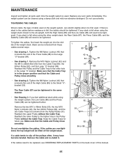
... the Press 3 Cable (88) can be tightened. Remove the cable and re-install it. If there is slack in the same manner. • See Drawing 3. Reattach the Pulley and the Cable Trap to the other weight stack, the Rear Cable (87), the Press Cable (88), and the Butterfly Cable (89) will need to be tightened. The weight system can be tightened in the cables before resistance is used . MAINTENANCE Inspect and tighten all parts...
... the Press 3 Cable (88) can be tightened. Remove the cable and re-install it. If there is slack in the same manner. • See Drawing 3. Reattach the Pulley and the Cable Trap to the other weight stack, the Rear Cable (87), the Press Cable (88), and the Butterfly Cable (89) will need to be tightened. The weight system can be tightened in the cables before resistance is used . MAINTENANCE Inspect and tighten all parts...

Canadian English Manual
Page 26
... Leg Press-13 26 4-Low Pulley Butterfly Cable (89) 4 5-Left Fly Arm 2 1-Right Fly Arm 3 IMPORTANT: If the cables have been assembled correctly. The starting and ending points of the High Cable (85), the Low Cable (86), the Rear Cable (87), the Press Cable (88), and the Butterfly Cable (89). CABLE DIAGRAMS The cable diagrams on this page and the next page show the proper route for each cable have been labeled. Use...
... Leg Press-13 26 4-Low Pulley Butterfly Cable (89) 4 5-Left Fly Arm 2 1-Right Fly Arm 3 IMPORTANT: If the cables have been assembled correctly. The starting and ending points of the High Cable (85), the Low Cable (86), the Rear Cable (87), the Press Cable (88), and the Butterfly Cable (89). CABLE DIAGRAMS The cable diagrams on this page and the next page show the proper route for each cable have been labeled. Use...

Canadian English Manual
Page 32
... 80 16 Cable Trap 81 3 "V"-pulley 82 21 90mm Pulley 83 1 Large Cable Trap 84 1 Large "U"-bracket 85 1 High Cable 86 1 Low Cable 87 1 Rear Cable 88 1 Press Cable 89 1 Butterfly Cable 90 16 Weight 91 2 M10 x 57mm Bolt 92 2 25mm Inner Cap 93 2 Weight Pin 94 2 Pulley Cover 95 1 M10 x 97mm Bolt 96 1 Handle # 1 User's Manual # 1 Exercise Guide # 2 Grease Packet Note: "#" indicates a non-illustrated part. Qty. Specifications are subject to change without notice. PART LIST-Model No. Qty...
... 80 16 Cable Trap 81 3 "V"-pulley 82 21 90mm Pulley 83 1 Large Cable Trap 84 1 Large "U"-bracket 85 1 High Cable 86 1 Low Cable 87 1 Rear Cable 88 1 Press Cable 89 1 Butterfly Cable 90 16 Weight 91 2 M10 x 57mm Bolt 92 2 25mm Inner Cap 93 2 Weight Pin 94 2 Pulley Cover 95 1 M10 x 97mm Bolt 96 1 Handle # 1 User's Manual # 1 Exercise Guide # 2 Grease Packet Note: "#" indicates a non-illustrated part. Qty. Specifications are subject to change without notice. PART LIST-Model No. Qty...

Canadian English Manual
Page 34
... give the following information: • the MODEL NUMBER of the product (WESY8630C.5) • the NAME of the product (WEIDER 8630 weight system) • the SERIAL NUMBER of the product (see the front cover of this manual) • the KEY NUMBER and DESCRIPTION of the part(s) (see the front cover of this manual. ORDERING REPLACEMENT PARTS To order replacement parts, please see the PART LIST and EXPLODED DRAWING attached at ICON's option, the product...
... give the following information: • the MODEL NUMBER of the product (WESY8630C.5) • the NAME of the product (WEIDER 8630 weight system) • the SERIAL NUMBER of the product (see the front cover of this manual) • the KEY NUMBER and DESCRIPTION of the part(s) (see the front cover of this manual. ORDERING REPLACEMENT PARTS To order replacement parts, please see the PART LIST and EXPLODED DRAWING attached at ICON's option, the product...


