

User Manual
Page 2
TABLE OF CONTENTS IMPORTANT PRECAUTIONS 3 BEFORE YOU BEGIN 4 ASSEMBLY 5 HOW TO USE THE HOME GYM SYSTEM 17 TROUBLESHOOTING AND MAINTENANCE 19 CABLE DIAGRAM 20 ORDERING REPLACEMENT PARTS 23 LIMITED WARRANTY Back Cover Note: A PART IDENTIFICATION CHART and a PART LIST/EXPLODED DRAWING are attached in the center of this manual. Remove the PART IDENTIFICATION CHART and the PART LIST/EXPLODED DRAWING before beginning assembly. 2
TABLE OF CONTENTS IMPORTANT PRECAUTIONS 3 BEFORE YOU BEGIN 4 ASSEMBLY 5 HOW TO USE THE HOME GYM SYSTEM 17 TROUBLESHOOTING AND MAINTENANCE 19 CABLE DIAGRAM 20 ORDERING REPLACEMENT PARTS 23 LIMITED WARRANTY Back Cover Note: A PART IDENTIFICATION CHART and a PART LIST/EXPLODED DRAWING are attached in the center of this manual. Remove the PART IDENTIFICATION CHART and the PART LIST/EXPLODED DRAWING before beginning assembly. 2
User Manual
Page 4
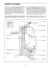
... to achieve the specific results you for selecting the versatile WEIDER® 8530 home gym system. The WEIDER® 8530 offers a selection of weight stations designed to the home gym system (see the front cover of the body. ASSEMBLED DIMENSIONS: Height: 74 in . Whether your goal is ...WESY8530C2. Width: 60 in the drawing below. after reading this manual carefully before calling...
... to achieve the specific results you for selecting the versatile WEIDER® 8530 home gym system. The WEIDER® 8530 offers a selection of weight stations designed to the home gym system (see the front cover of the body. ASSEMBLED DIMENSIONS: Height: 74 in . Whether your goal is ...WESY8530C2. Width: 60 in the drawing below. after reading this manual carefully before calling...
User Manual
Page 5
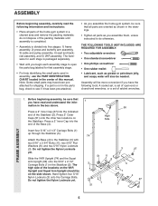
... the parts bag, check to see if it has been pre-attached. • As you assemble the home gym system, be sure that you begin each stage is divided into the end of this manual. Attach the Base (4) to do not dispose of ratchet wrenches. If a part is not ...in a cleared area and remove the packing materials; Before beginning assembly, be more convenient if you assemble them, unless instructed to the Stabilizer (5) with two 5/16" ...
... the parts bag, check to see if it has been pre-attached. • As you assemble the home gym system, be sure that you begin each stage is divided into the end of this manual. Attach the Base (4) to do not dispose of ratchet wrenches. If a part is not ...in a cleared area and remove the packing materials; Before beginning assembly, be more convenient if you assemble them, unless instructed to the Stabilizer (5) with two 5/16" ...
User Manual
Page 10
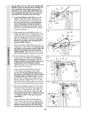
... sure that the Cable is positioned to hold the Cable in place. Identify the three cables by their lengths, and note the positions of this manual. Be sure that the Cable and Pulley move smoothly. 15 58 15 66 12 21 57 58 57 10 Locate the Medium Cable (58). Be... the indicated side of the Pulley and that the Long Cable Trap (31) holds the Cable in place. 86 58 31 31 86 50 CABLE ASSEMBLY Route the Medium Cable (58) around the "V"Pulley (50) on the Left Arm (47). Tighten the 3/8" x 2 1/2" Bolt (86) and the 3/8" Nylon Locknut (not shown). 15...
... sure that the Cable is positioned to hold the Cable in place. Identify the three cables by their lengths, and note the positions of this manual. Be sure that the Cable and Pulley move smoothly. 15 58 15 66 12 21 57 58 57 10 Locate the Medium Cable (58). Be... the indicated side of the Pulley and that the Long Cable Trap (31) holds the Cable in place. 86 58 31 31 86 50 CABLE ASSEMBLY Route the Medium Cable (58) around the "V"Pulley (50) on the Left Arm (47). Tighten the 3/8" x 2 1/2" Bolt (86) and the 3/8" Nylon Locknut (not shown). 15...
User Manual
Page 16
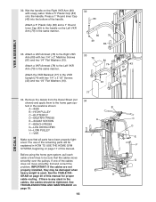
...in the same manner. See the CABLE DIA- See TROUBLESHOOTING AND MAINTENANCE on page 17 of this manual. Attach a VKR Armrest (78) to the handle on the Right VKR Arm (80) with soapy... water. Wet the handle on the Left VKR Arm (79) in the locations shown: B A -8530 B -HIGH PULLEY C -BUTTERFLY D-MILITARY PRESS A E -SQUAT STATION F -BENCH PRESS G-LEG DEVELOPER H-LOW PULLEY I -VKR...74 10 81 77 34. tem in the same manner. 32 83 80 49 79 83 VKR ASSEMBLY 33. IMPORTANT: If the cables are not properly installed, they may be explained in HOW TO USE...
...in the same manner. See the CABLE DIA- See TROUBLESHOOTING AND MAINTENANCE on page 17 of this manual. Attach a VKR Armrest (78) to the handle on the Right VKR Arm (80) with soapy... water. Wet the handle on the Left VKR Arm (79) in the locations shown: B A -8530 B -HIGH PULLEY C -BUTTERFLY D-MILITARY PRESS A E -SQUAT STATION F -BENCH PRESS G-LEG DEVELOPER H-LOW PULLEY I -VKR...74 10 81 77 34. tem in the same manner. 32 83 80 49 79 83 VKR ASSEMBLY 33. IMPORTANT: If the cables are not properly installed, they may be explained in HOW TO USE...
User Manual
Page 25
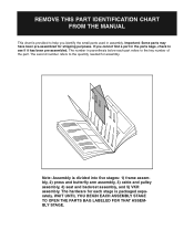
... each stage is packaged separately. The number in assembly. WAIT UNTIL YOU BEGIN EACH ASSEMBLY STAGE TO OPEN THE PARTS BAG LABELED FOR THAT ASSEMBLY STAGE. REMOVE THIS PART IDENTIFICATION CHART FROM THE MANUAL This chart is divided into five stages: 1) frame assembly, 2) press and butterfly arm assembly, 3) cable and pulley assembly, 4) seat and backrest assembly, and 5) VKR...
... each stage is packaged separately. The number in assembly. WAIT UNTIL YOU BEGIN EACH ASSEMBLY STAGE TO OPEN THE PARTS BAG LABELED FOR THAT ASSEMBLY STAGE. REMOVE THIS PART IDENTIFICATION CHART FROM THE MANUAL This chart is divided into five stages: 1) frame assembly, 2) press and butterfly arm assembly, 3) cable and pulley assembly, 4) seat and backrest assembly, and 5) VKR...


