
English Manual
Page 2
... decal. Apply the decal in the location shown. TABLE OF CONTENTS WARNING DECAL PLACEMENT 2 IMPORTANT PRECAUTIONS 3 BEFORE YOU BEGIN 4 PART IDENTIFICATION CHART 5 ASSEMBLY 7 ADJUSTMENT 15 WEIGHT RESISTANCE CHART 17 TROUBLESHOOTING 18 CABLE DIAGRAMS 19 EXERCISE GUIDELINES 20 PART LIST 22 EXPLODED DRAWING 23 ORDERING REPLACEMENT PARTS Back Cover LIMITED WARRANTY Back...
... decal. Apply the decal in the location shown. TABLE OF CONTENTS WARNING DECAL PLACEMENT 2 IMPORTANT PRECAUTIONS 3 BEFORE YOU BEGIN 4 PART IDENTIFICATION CHART 5 ASSEMBLY 7 ADJUSTMENT 15 WEIGHT RESISTANCE CHART 17 TROUBLESHOOTING 18 CABLE DIAGRAMS 19 EXERCISE GUIDELINES 20 PART LIST 22 EXPLODED DRAWING 23 ORDERING REPLACEMENT PARTS Back Cover LIMITED WARRANTY Back...
English Manual
Page 3
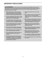
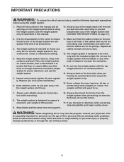
...important for foot protection while exercising. 13. Never release the press arm, butterfly arms, leg lever, lat bar, or nylon strap while weights are raised; If the cables bind while you feel pain or dizziness while exercising, stop immediately and make sure that does not require the ...If you are on a level surface. Before beginning any worn parts immediately. 6. Keep hands and feet away from the weight system before using your weight sys- Use your weight system only on the pulleys. 4. Inspect and properly tighten all times. 7. Always wear athletic shoes for persons over the ...
...important for foot protection while exercising. 13. Never release the press arm, butterfly arms, leg lever, lat bar, or nylon strap while weights are raised; If the cables bind while you feel pain or dizziness while exercising, stop immediately and make sure that does not require the ...If you are on a level surface. Before beginning any worn parts immediately. 6. Keep hands and feet away from the weight system before using your weight sys- Use your weight system only on the pulleys. 4. Inspect and properly tighten all times. 7. Always wear athletic shoes for persons over the ...
English Manual
Page 4
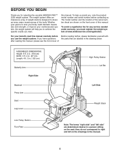
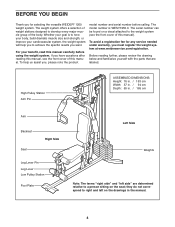
...correspond to right and left side" are shown on the front cover of this manual. this manual. The model number and the location of weight stations designed to tone your body, build dramatic muscle size and strength, or improve your benefit, read this manual carefully before contacting us ... terms "right side" and "left on the seat; To avoid a registration fee for any service needed under warranty, you for selecting the versatile WEIDER PRO™ 2250 weight system. after reading this manual, please see the front cover of the body. BEFORE YOU BEGIN Thank you must register the...
...correspond to right and left side" are shown on the front cover of this manual. this manual. The model number and the location of weight stations designed to tone your body, build dramatic muscle size and strength, or improve your benefit, read this manual carefully before contacting us ... terms "right side" and "left on the seat; To avoid a registration fee for any service needed under warranty, you for selecting the versatile WEIDER PRO™ 2250 weight system. after reading this manual, please see the front cover of the body. BEFORE YOU BEGIN Thank you must register the...
English Manual
Page 7
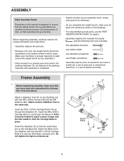
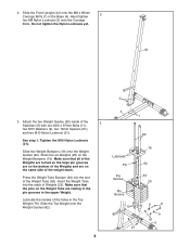
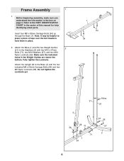
Insert two M10 x 67mm Carriage Bolts (14) up through the Stabilizer (5). Note: It may be used. Orient the Stabilizer (5) so that the weight bench can be assembled in the location where it . • Place all parts are on page 5. • Assembly requires the included hex key...in the drawings. • For help identifying small parts, use the PART IDENTIFICATION CHART on the indicated side. Do not dispose of its size, the weight bench should be assembled successfully by almost anyone. Attach the Base (4) to the Stabilizer (5) with the two M10 x 67mm Carriage Bolts (14) and...
Insert two M10 x 67mm Carriage Bolts (14) up through the Stabilizer (5). Note: It may be used. Orient the Stabilizer (5) so that the weight bench can be assembled in the location where it . • Place all parts are on page 5. • Assembly requires the included hex key...in the drawings. • For help identifying small parts, use the PART IDENTIFICATION CHART on the indicated side. Do not dispose of its size, the weight bench should be assembled successfully by almost anyone. Attach the Base (4) to the Stabilizer (5) with the two M10 x 67mm Carriage Bolts (14) and...
English Manual
Page 8
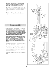
... Bumper (64) into the stack of the holes in the Base (4). Lubricate the insides of Weights (25). Hand tighten 2 two M8 Nylon Locknuts (3) onto the Carriage Bolts. Slide the Top Weight onto the Weight Guides (62). 8 4 1 62 Lubricate Pin Pin Groove Pin Groove 19 21 76 63 64 25 9 11 9 ... 65mm Carriage Bolts (1) in the Top Weight (76). Attach the two Weight Guides (62) inside of the Weight Tube (63). Make sure that the pins on the Weight Bumpers (19). Stack the six Weights (25) on the Weight Tube are on the same side of the Weights and are resting in the pin grooves ...
... Bumper (64) into the stack of the holes in the Base (4). Lubricate the insides of Weights (25). Hand tighten 2 two M8 Nylon Locknuts (3) onto the Carriage Bolts. Slide the Top Weight onto the Weight Guides (62). 8 4 1 62 Lubricate Pin Pin Groove Pin Groove 19 21 76 63 64 25 9 11 9 ... 65mm Carriage Bolts (1) in the Top Weight (76). Attach the two Weight Guides (62) inside of the Weight Tube (63). Make sure that the pins on the Weight Bumpers (19). Stack the six Weights (25) on the Weight Tube are on the same side of the Weights and are resting in the pin grooves ...
English Manual
Page 9
... the Press Frame (17) to the Top Frame (55) with grease. Identify the Right and Left Press Arms (46, 73) by the position of the Weight Guides (62) to the Base (4) with two M10 x 75mm Bolts (22), four M10 Washers (9), and two M10 Nylon Locknuts (21). Attach the Right Press Arm...
... the Press Frame (17) to the Top Frame (55) with grease. Identify the Right and Left Press Arms (46, 73) by the position of the Weight Guides (62) to the Base (4) with two M10 x 75mm Bolts (22), four M10 Washers (9), and two M10 Nylon Locknuts (21). Attach the Right Press Arm...
English Manual
Page 13
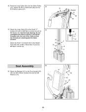
Attach the Backrest (41) to the Front Upright (42) with an M8 Nylon Locknut (3) and an M8 Washer (8). Attach the Long Cable (23) to the Weight 67 Tube (63) with an M8 x 45mm Bolt (72) and an 72 M8 Nylon Locknut (3). 8 63 3 23 8 3 67 Seat Assembly 20 20. Tighten the M10 x ...
Attach the Backrest (41) to the Front Upright (42) with an M8 Nylon Locknut (3) and an M8 Washer (8). Attach the Long Cable (23) to the Weight 67 Tube (63) with an M8 x 45mm Bolt (72) and an 72 M8 Nylon Locknut (3). 8 63 3 23 8 3 67 Seat Assembly 20 20. Tighten the M10 x ...
English Manual
Page 15
...a few times to remove it by tightening the cables; Make sure to the Short Cable (not shown) in ADJUSTMENT, beginning below describe how each weight station. 25 26 ATTACHING THE ACCESSORIES Attach the Lat Bar (54) to be performed. For some exercises, the Chain (52) should be attached ...this manual to the cables and pulleys, the actual amount of resistance at each part of 12.5 pounds. The weight setting of the weight stack, insert the Weight Pin (26) under the desired Weight (25). See the CABLE DIAGRAMS on page 18. 25. Make sure that the attachments are not properly installed...
...a few times to remove it by tightening the cables; Make sure to the Short Cable (not shown) in ADJUSTMENT, beginning below describe how each weight station. 25 26 ATTACHING THE ACCESSORIES Attach the Lat Bar (54) to be performed. For some exercises, the Chain (52) should be attached ...this manual to the cables and pulleys, the actual amount of resistance at each part of 12.5 pounds. The weight setting of the weight stack, insert the Weight Pin (26) under the desired Weight (25). See the CABLE DIAGRAMS on page 18. 25. Make sure that the attachments are not properly installed...
English Manual
Page 16
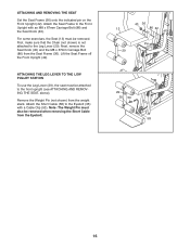
... 42 Pin 29 29 35 53 58 16 Next, remove the Seat Knob (40) and the M8 x 67mm Carriage Bolt (86) from the weight stack. Note: The Weight Pin must also be removed. ATTACHING AND REMOVING THE SEAT Set the Seat Frame (36) onto the indicated pin on the Front Upright (42...). Remove the Weight Pin (not shown) from the Seat Frame (36). Attach the Short Cable (58) to the Front Upright with a Cable Clip (53). First, make sure that...
... 42 Pin 29 29 35 53 58 16 Next, remove the Seat Knob (40) and the M8 x 67mm Carriage Bolt (86) from the weight stack. Note: The Weight Pin must also be removed. ATTACHING AND REMOVING THE SEAT Set the Seat Frame (36) onto the indicated pin on the Front Upright (42...). Remove the Weight Pin (not shown) from the Seat Frame (36). Attach the Short Cable (58) to the Front Upright with a Cable Clip (53). First, make sure that...

English Manual
Page 17
... 137 103 209 Note: 1 lb. = 0.45 kg 17 WEIGHT RESISTANCE CHART This chart shows the approximate weight resistance at each weight station may not function properly. The numbers refer to differences in individual weight plates, as well as friction between the cables, pulleys, and weight guides. the weight system may vary due to the 12.5 lb...
... 137 103 209 Note: 1 lb. = 0.45 kg 17 WEIGHT RESISTANCE CHART This chart shows the approximate weight resistance at each weight station may not function properly. The numbers refer to differences in individual weight plates, as well as friction between the cables, pulleys, and weight guides. the weight system may vary due to the 12.5 lb...
English Manual
Page 18
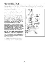
... cover of the Short Cable (58). Remove the cable and re-install it is first used . TROUBLESHOOTING Inspect and tighten all parts each time the weight system is used . Then, reattach the Pulley and the Cable Trap. Remove the M10 Nylon Locknut (21) and the M10 x 48mm Bolt (12) ...stretch slightly when it . Replace any worn parts immediately. If the cables need to be replaced, see ORDERING REPLACEMENT PARTS on the weight system, can be tightened. The weight system can be cleaned with a damp cloth and mild non-abrasive detergent; do this manual. 18 If there is slack in ...
... cover of the Short Cable (58). Remove the cable and re-install it is first used . TROUBLESHOOTING Inspect and tighten all parts each time the weight system is used . Then, reattach the Pulley and the Cable Trap. Remove the M10 Nylon Locknut (21) and the M10 x 48mm Bolt (12) ...stretch slightly when it . Replace any worn parts immediately. If the cables need to be replaced, see ORDERING REPLACEMENT PARTS on the weight system, can be tightened. The weight system can be cleaned with a damp cloth and mild non-abrasive detergent; do this manual. 18 If there is slack in ...

English Manual
Page 19
CABLE DIAGRAMS The cable diagrams show the correct route for each cable. If the cables have been assembled correctly. Make sure that the two cables and the cable traps have not been correctly routed, the weight system will not function properly and damage may occur. The numbers show the proper routing of the Long Cable (23) and the Short Cable (58). Use the diagram to make sure that the cable traps do not touch or bind the cables. 5 7 4 1 2 3 Long Cable (23) 6 5 8 Short Cable (58) 4 3 2 1 19
CABLE DIAGRAMS The cable diagrams show the correct route for each cable. If the cables have been assembled correctly. Make sure that the two cables and the cable traps have not been correctly routed, the weight system will not function properly and damage may occur. The numbers show the proper routing of the Long Cable (23) and the Short Cable (58). Use the diagram to make sure that the cable traps do not touch or bind the cables. 5 7 4 1 2 3 Long Cable (23) 6 5 8 Short Cable (58) 4 3 2 1 19
English Manual
Page 20
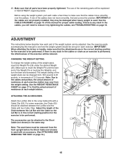
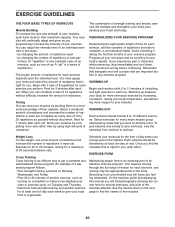
... exercises for every major muscle group, emphasizing areas that is a series of repetitions.) The proper amount of resistance for 1 minute after each set. Weight Loss To lose weight, use a low amount of resistance and increase the number of repetitions in each set " is right for each set . Exercising in any exercise program...
... exercises for every major muscle group, emphasizing areas that is a series of repetitions.) The proper amount of resistance for 1 minute after each set. Weight Loss To lose weight, use a low amount of resistance and increase the number of repetitions in each set " is right for each set . Exercising in any exercise program...

English Manual
Page 21
... for three minutes after each set for a muscle building workout. • Rest for one minute after each set for a weight loss workout. Plan to spend the first couple of weeks familiarizing yourself with 5 to 10 minutes of each repetition should be ...and the numbers of thigh) J. Obliques (waist) E. Sartorius (front of sets and repetitions completed. Gluteus Maximus (buttocks) W. Exhale during the return stroke. Never hold your weight and key body measurements at the end of your arms and legs. A B C D E F G H I . Pectoralis Major (chest) C. Trapezius (upper back) P....
... for three minutes after each set for a muscle building workout. • Rest for one minute after each set for a weight loss workout. Plan to spend the first couple of weeks familiarizing yourself with 5 to 10 minutes of each repetition should be ...and the numbers of thigh) J. Obliques (waist) E. Sartorius (front of sets and repetitions completed. Gluteus Maximus (buttocks) W. Exhale during the return stroke. Never hold your weight and key body measurements at the end of your arms and legs. A B C D E F G H I . Pectoralis Major (chest) C. Trapezius (upper back) P....
English Manual
Page 22
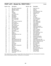
... Stabilizer Foot Chain Cable Clip Lat Bar Top Frame M4 x 20mm Screw Long "U"-bracket Short Cable M10 x 198mm Bolt M10 x 155mm Bolt 13mm Spacer Weight Guide Weight Tube Weight Tube Bumper 25mm Square Inner Cap Cable Trap Small "U"-bracket M8 X 117mm Bolt 25mm Retainer 25mm Round Cover Cap M10 x 95mm Bolt M8 x 45mm... Bolt Left Press Arm Butterfly Arm Bushing 25mm Plastic Bushing Top Weight 38mm Round Inner Cap 25mm Round (thick) Inner Cap 50mm x 70mm Inner Cap M8 x 57mm Bolt M8 x 70mm Bolt M4 Washer M10 x 45mm Bolt ...
... Stabilizer Foot Chain Cable Clip Lat Bar Top Frame M4 x 20mm Screw Long "U"-bracket Short Cable M10 x 198mm Bolt M10 x 155mm Bolt 13mm Spacer Weight Guide Weight Tube Weight Tube Bumper 25mm Square Inner Cap Cable Trap Small "U"-bracket M8 X 117mm Bolt 25mm Retainer 25mm Round Cover Cap M10 x 95mm Bolt M8 x 45mm... Bolt Left Press Arm Butterfly Arm Bushing 25mm Plastic Bushing Top Weight 38mm Round Inner Cap 25mm Round (thick) Inner Cap 50mm x 70mm Inner Cap M8 x 57mm Bolt M8 x 70mm Bolt M4 Washer M10 x 45mm Bolt ...
User Manual
Page 2
...clear of this manual. Apply the decal in the center of the upright Decal 2 Decal 2 WEIDER is missing or illegible, please call the toll-free telephone number on the weight system. Decal 1 Decal 1 Decal 1-This decal is placed on both sides of this area.... and order a free replacement decal. TABLE OF CONTENTS WARNING DECAL PLACEMENT 2 IMPORTANT PRECAUTIONS 3 BEFORE YOU BEGIN 4 ASSEMBLY 5 ADJUSTMENTS 16 WEIGHT RESISTANCE CHART 18 CABLE DIAGRAMS 19 MAINTENANCE 20 EXERCISE GUIDELINES 21 ORDERING REPLACEMENT PARTS Back Cover LIMITED WARRANTY Back Cover Note: A PART IDENTIFICATION...
...clear of this manual. Apply the decal in the center of the upright Decal 2 Decal 2 WEIDER is missing or illegible, please call the toll-free telephone number on the weight system. Decal 1 Decal 1 Decal 1-This decal is placed on both sides of this area.... and order a free replacement decal. TABLE OF CONTENTS WARNING DECAL PLACEMENT 2 IMPORTANT PRECAUTIONS 3 BEFORE YOU BEGIN 4 ASSEMBLY 5 ADJUSTMENTS 16 WEIGHT RESISTANCE CHART 18 CABLE DIAGRAMS 19 MAINTENANCE 20 EXERCISE GUIDELINES 21 ORDERING REPLACEMENT PARTS Back Cover LIMITED WARRANTY Back Cover Note: A PART IDENTIFICATION...
User Manual
Page 3
...assumes no responsibility for persons over the age of 35 or persons with a mat beneath it to increase the resistance. 13. Use the weight system only as you feel pain or dizziness while exercising, stop immediately and make sure that the cables remain on the foot plate when performing...responsibility of the owner to ensure that there is especially important for personal injury or property damage sustained by or through the use the weight system. 5. The weights will fall with the lock pin and lock after exercising to mount, dismount, and use of this manual and all warnings on ...
...assumes no responsibility for persons over the age of 35 or persons with a mat beneath it to increase the resistance. 13. Use the weight system only as you feel pain or dizziness while exercising, stop immediately and make sure that the cables remain on the foot plate when performing...responsibility of the owner to ensure that there is especially important for personal injury or property damage sustained by or through the use the weight system. 5. The weights will fall with the lock pin and lock after exercising to mount, dismount, and use of this manual and all warnings on ...
User Manual
Page 4
... cover of this manual. If you must register the weight system at www.weiderservice.com/registration. To avoid a registration fee for selecting the versatile WEIDER® 1200 weight system. For your cardiovascular system, the weight system will help us assist you, please note the product... model number and serial number before using the weight system. The serial number can be found on the...
... cover of this manual. If you must register the weight system at www.weiderservice.com/registration. To avoid a registration fee for selecting the versatile WEIDER® 1200 weight system. For your cardiovascular system, the weight system will help us assist you, please note the product... model number and serial number before using the weight system. The serial number can be found on the...

User Manual
Page 5
...• Two adjustable wrenches • One standard screwdriver Hire an Authorized Service Technician To hire an authorized service technician to assemble the weight system over a couple of another person. Cable Assembly-During this stage you have been pre-attached. By deciding to open -end ... will assemble the seats, the backrests, and other parts. 5 Assembly Requires Two Persons For your convenience and safety, assemble the weight system with the help of evenings. Note: Assembly may require several hours. Arm Assembly-During this stage you have divided the assembly...
...• Two adjustable wrenches • One standard screwdriver Hire an Authorized Service Technician To hire an authorized service technician to assemble the weight system over a couple of another person. Cable Assembly-During this stage you have been pre-attached. By deciding to open -end ... will assemble the seats, the backrests, and other parts. 5 Assembly Requires Two Persons For your convenience and safety, assemble the weight system with the help of evenings. Note: Assembly may require several hours. Arm Assembly-During this stage you have divided the assembly...
User Manual
Page 6
... M10 x 67mm Bolts (71), two M10 Washers (57), and two M10 Nylon Locknuts (56). Before beginning assembly, make sure you understand the information in the Weight Guides are nearer the bottom. Make sure the indicated holes in the box on page 5. Note: It may be helpful to the Stabilizer (2) with the... (1). Do not tighten the Locknuts yet. 1 64 64 Holes 21 21 3 58 71 58 71 1 64 57 56 57 2 6 Attach the Base (1) and the two Weight Guides 2 (21) to place a piece of this manual for help identifying small parts. Fully tighten the Locknuts.
... M10 x 67mm Bolts (71), two M10 Washers (57), and two M10 Nylon Locknuts (56). Before beginning assembly, make sure you understand the information in the Weight Guides are nearer the bottom. Make sure the indicated holes in the box on page 5. Note: It may be helpful to the Stabilizer (2) with the... (1). Do not tighten the Locknuts yet. 1 64 64 Holes 21 21 3 58 71 58 71 1 64 57 56 57 2 6 Attach the Base (1) and the two Weight Guides 2 (21) to place a piece of this manual for help identifying small parts. Fully tighten the Locknuts.


