
User Guide
Page 52
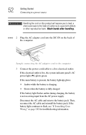
If the electrical outlet is not receiving input from the AC power supply. If the main battery is present, the battery light glows: ❖ Amber while the battery is charging ❖ Green when the battery is fully charged ... battery is live electrical outlet. Sample connecting the AC adapter cord to the computer 3 Connect the power cord/cable to a live , the system indicator panel's AC power light ( ) glows green. 52 Getting Started Connecting to a power source Handling the cord on this product will expose you to lead, a chemical known to the State...
If the electrical outlet is not receiving input from the AC power supply. If the main battery is present, the battery light glows: ❖ Amber while the battery is charging ❖ Green when the battery is fully charged ... battery is live electrical outlet. Sample connecting the AC adapter cord to the computer 3 Connect the power cord/cable to a live , the system indicator panel's AC power light ( ) glows green. 52 Getting Started Connecting to a power source Handling the cord on this product will expose you to lead, a chemical known to the State...

User Guide
Page 216
This appendix shows the shapes of the typical AC power cord/cable connectors for various parts of the world. USA and Canada United Kingdom UL approved CSA approved Australia AS approved BS approved Europe VDA approved NEMKO approved 216 Appendix B Power Cord/Cable Connectors The computer features a universal power supply you can use worldwide.
This appendix shows the shapes of the typical AC power cord/cable connectors for various parts of the world. USA and Canada United Kingdom UL approved CSA approved Australia AS approved BS approved Europe VDA approved NEMKO approved 216 Appendix B Power Cord/Cable Connectors The computer features a universal power supply you can use worldwide.
User Guide
Page 251
...taking care of your battery 122 turning on 55 universal power supply 216 power button 56, 63 power mode creating new 165 customizing 165 power source 50 power usage mode hot key 126 power usage mode hot key 210 power usage modes 125 powering down using Standby 108 precautions 46, 53 other computer ...cannot read a diskette 198 changing display properties 195 checking device properties 190 compact discs not running correctly 199 computer will not power up 182 contacting Toshiba 205, 206 corrupted/damaged data files 197 Device Manager 189 disabling a device 189, 190 disk drive is slow 197 display...
...taking care of your battery 122 turning on 55 universal power supply 216 power button 56, 63 power mode creating new 165 customizing 165 power source 50 power usage mode hot key 126 power usage mode hot key 210 power usage modes 125 powering down using Standby 108 precautions 46, 53 other computer ...cannot read a diskette 198 changing display properties 195 checking device properties 190 compact discs not running correctly 199 computer will not power up 182 contacting Toshiba 205, 206 corrupted/damaged data files 197 Device Manager 189 disabling a device 189, 190 disk drive is slow 197 display...

Maintenance Manual
Page 6
...2 Troubleshooting Procedures 2.1 Troubleshooting Introduction Error! Bookmark not defined. 2.2 Troubleshooting Flowchart Error! Bookmark not defined. 2.4 Display Troubleshooting Error! Bookmark not defined. 2.3 Power Supply Troubleshooting Error! Bookmark not defined. 2.5 Keyboard Troubleshooting 2-15 2.6 External USB Devices Troubleshooting 2-17 2.7 TV-Out Failure Troubleshooting 2-19 2.8 Printer Port Troubleshooting 2-... 2-27 2.12 PCMCIA Troubleshooting 2-29 2.13 IEEE 1394 Troubleshooting 2-31 2.14 Wireless LAN Troubleshooting 2-33 vi Tecra A3/S2 Maintenance Manual
...2 Troubleshooting Procedures 2.1 Troubleshooting Introduction Error! Bookmark not defined. 2.2 Troubleshooting Flowchart Error! Bookmark not defined. 2.4 Display Troubleshooting Error! Bookmark not defined. 2.3 Power Supply Troubleshooting Error! Bookmark not defined. 2.5 Keyboard Troubleshooting 2-15 2.6 External USB Devices Troubleshooting 2-17 2.7 TV-Out Failure Troubleshooting 2-19 2.8 Printer Port Troubleshooting 2-... 2-27 2.12 PCMCIA Troubleshooting 2-29 2.13 IEEE 1394 Troubleshooting 2-31 2.14 Wireless LAN Troubleshooting 2-33 vi Tecra A3/S2 Maintenance Manual

Maintenance Manual
Page 12
Chapter 1 Contents 1 Hardware Overview 1.1 Features ...1-5 1.2 System Unit...1-10 1.3 2.5-inch Hard Disk Drive 1-14 1.4 Removable Drives...1-15 1.4.1 DVD-R/-RW Drive Error! Bookmark not defined. 1.4.2 DVD-ROM Drive 1-15 1.4.3 CD-ROM Drive 1-15 1.4.4 DVD±R/±RW Drive 1-15 1.4.5 DVD Super Multi Drive 1-17 1.5 Power Supply ...1-15 1.6 Batteries ...1-21 1.6.1 Main Battery 1-21 1.6.2 RTC battery 1-22 Tecra A3/S2 Series Maintenance Manual 1-iii
Chapter 1 Contents 1 Hardware Overview 1.1 Features ...1-5 1.2 System Unit...1-10 1.3 2.5-inch Hard Disk Drive 1-14 1.4 Removable Drives...1-15 1.4.1 DVD-R/-RW Drive Error! Bookmark not defined. 1.4.2 DVD-ROM Drive 1-15 1.4.3 CD-ROM Drive 1-15 1.4.4 DVD±R/±RW Drive 1-15 1.4.5 DVD Super Multi Drive 1-17 1.5 Power Supply ...1-15 1.6 Batteries ...1-21 1.6.1 Main Battery 1-21 1.6.2 RTC battery 1-22 Tecra A3/S2 Series Maintenance Manual 1-iii
Maintenance Manual
Page 26
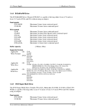
Read speeds DVD-ROM CD-ROM Maximum 8 times faster rotational speed Maximum 24 times faster rotational speed Tecra A3/S2 Series Maintenance Manual 1-17 1.5 Power Supply 1 Hardware Overview 1.4.4 DVD±R/±RW Drive The DVD±R/±RW drive (Pioneer DVR-K15) is capable of driving either 12cm (4.72-inch)...DVD DVD-ROM [DVD-5, DVD-9, DVD-10, DVD-18] DVD-R DVD-RW DVD+R DVD+RW 1.4.5 DVD Super Multi Drive The DVD Super Multi Drive (Toshiba TS-L632A, Matsushita UJ-830B, UJ-831B or TEAC DVW28E) is capable of driving either 12cm (4.72-inch) or 8cm (3.15-inch) DVDs and CDs...
Read speeds DVD-ROM CD-ROM Maximum 8 times faster rotational speed Maximum 24 times faster rotational speed Tecra A3/S2 Series Maintenance Manual 1-17 1.5 Power Supply 1 Hardware Overview 1.4.4 DVD±R/±RW Drive The DVD±R/±RW drive (Pioneer DVR-K15) is capable of driving either 12cm (4.72-inch)...DVD DVD-ROM [DVD-5, DVD-9, DVD-10, DVD-18] DVD-R DVD-RW DVD+R DVD+RW 1.4.5 DVD Super Multi Drive The DVD Super Multi Drive (Toshiba TS-L632A, Matsushita UJ-830B, UJ-831B or TEAC DVW28E) is capable of driving either 12cm (4.72-inch) or 8cm (3.15-inch) DVDs and CDs...
Maintenance Manual
Page 28
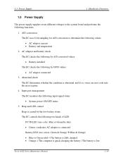
...and if so, stores an error code into the error register. 4. 1.5 Power Supply 1 Hardware Overview 1.5 Power Supply The power supply supplies seven different voltages to determine the following values: • AC adaptor current ...• Battery and temperature 2. AC adaptor and battery check The EC checks the following by A/D converted values: • Battery installed The EC checks the following input signal status: • System power ON/OFF status 5. Tecra A3...
...and if so, stores an error code into the error register. 4. 1.5 Power Supply 1 Hardware Overview 1.5 Power Supply The power supply supplies seven different voltages to determine the following values: • AC adaptor current ...• Battery and temperature 2. AC adaptor and battery check The EC checks the following by A/D converted values: • Battery installed The EC checks the following input signal status: • System power ON/OFF status 5. Tecra A3...

Maintenance Manual
Page 29
Detection of full charge 8. Battery capacity calculation The EC reads battery remaining and percentage capacity from the battery through SMBus. 1-20 Tecra A3/S2 Series Maintenance Manual Power ON/OFF sequence When power is installed, the EC communicates with the E2PROM in the battery to drive the system after 3 minutes. • LB1 = ...battery for 12 more minutes. • LB0 = The battery won't be able to read information of the newly installed battery. 10. 1 Hardware Overview 1.5 Power Supply 6. New battery installation When a new battery is turned on or off, the EC starts the...
Detection of full charge 8. Battery capacity calculation The EC reads battery remaining and percentage capacity from the battery through SMBus. 1-20 Tecra A3/S2 Series Maintenance Manual Power ON/OFF sequence When power is installed, the EC communicates with the E2PROM in the battery to drive the system after 3 minutes. • LB1 = ...battery for 12 more minutes. • LB0 = The battery won't be able to read information of the newly installed battery. 10. 1 Hardware Overview 1.5 Power Supply 6. New battery installation When a new battery is turned on or off, the EC starts the...
Maintenance Manual
Page 30
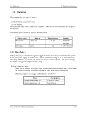
...voltage 14.8 V 3 V Capacity 6450mAH/ 4300mAH 14 mAH/15 mAH 1.6.1 Main Battery Battery charging is controlled by a power supply microprocessor that is on . Status Normal charge (power on the system board. 1.6 Batteries 1 Hardware Overview 1.6 Batteries The computer has two types of quick charge: quick ...) ‰ RTC battery The removable main battery pack is the computer's main power source when the AC adaptor is powered on or off ) Charging time 12 hours or longer About 4 hours Tecra A3/S2 Series Maintenance Manual 1-21 The times required for charges are attached to the...
...voltage 14.8 V 3 V Capacity 6450mAH/ 4300mAH 14 mAH/15 mAH 1.6.1 Main Battery Battery charging is controlled by a power supply microprocessor that is on . Status Normal charge (power on the system board. 1.6 Batteries 1 Hardware Overview 1.6 Batteries The computer has two types of quick charge: quick ...) ‰ RTC battery The removable main battery pack is the computer's main power source when the AC adaptor is powered on or off ) Charging time 12 hours or longer About 4 hours Tecra A3/S2 Series Maintenance Manual 1-21 The times required for charges are attached to the...
Maintenance Manual
Page 31
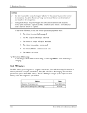
Using quick charge, the power supply microprocessor automatically stops the charge after eight hours regardless of the condition of full charge A full charge is detected from the battery pack through SMBus when the battery is charging. 1.6.2 RTC battery The RTC battery provides power to explode. The ...the following occurs, the battery quick charge process stops. 1. The battery or output voltage is powered on ) Data preservation period (full charge) Time About 24 hours 1 month 1-22 Tecra A3/S2 Series Maintenance Manual The RTC battery is bad. ‰ Detection of the battery. ...
Using quick charge, the power supply microprocessor automatically stops the charge after eight hours regardless of the condition of full charge A full charge is detected from the battery pack through SMBus when the battery is charging. 1.6.2 RTC battery The RTC battery provides power to explode. The ...the following occurs, the battery quick charge process stops. 1. The battery or output voltage is powered on ) Data preservation period (full charge) Time About 24 hours 1 month 1-22 Tecra A3/S2 Series Maintenance Manual The RTC battery is bad. ‰ Detection of the battery. ...

Maintenance Manual
Page 34
... 2-1 2.2 Troubleshooting Flowchart 2-2 2.3 Power Supply Troubleshooting 2-7 2.4 Display Troubleshooting 2-12 2.5 Keyboard Troubleshooting 2-15 2.6 External USB Devices Troubleshooting 2-17 2.7 TV-Out Failure Troubleshooting 2-19 2.8 Printer Port Troubleshooting 2-21 2.9 TouchPad Troubleshooting 2-23 2.10 Speaker Troubleshooting 2-25 2.11 Modem Troubleshooting 2-27 2.12 PCMCIA Troubleshooting 2-29 2.13 IEEE 1394 Troubleshooting 2-31 2.14 Wireless LAN Troubleshooting 2-33 Tecra A3/S2 Series...
... 2-1 2.2 Troubleshooting Flowchart 2-2 2.3 Power Supply Troubleshooting 2-7 2.4 Display Troubleshooting 2-12 2.5 Keyboard Troubleshooting 2-15 2.6 External USB Devices Troubleshooting 2-17 2.7 TV-Out Failure Troubleshooting 2-19 2.8 Printer Port Troubleshooting 2-21 2.9 TouchPad Troubleshooting 2-23 2.10 Speaker Troubleshooting 2-25 2.11 Modem Troubleshooting 2-27 2.12 PCMCIA Troubleshooting 2-29 2.13 IEEE 1394 Troubleshooting 2-31 2.14 Wireless LAN Troubleshooting 2-33 Tecra A3/S2 Series...
Maintenance Manual
Page 35
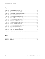
... 2-4 Figure 2-5 Figure 2-6 Figure 2-7 Figure 2-8 Figure 2-9 Figure 2-10 Figure 2-11 Figure 2-12 Figure 2-13 Figure 2-14 Troubleshooting flowchart (1/2 2-3 Troubleshooting flowchart (2/2 2-4 Power Supply Troubleshooting Process 2-7 Display troubleshooting process 2-12 Keyboard troubleshooting process 2-15 External USB device troubleshooting process 2-17 TV-out troubleshooting process 2-19 Printer port troubleshooting process...process 2-34 Wireless LAN troubleshooting process 2-36 Tables Table 2-1 Battery LED ...2-8 Table 2-2 DC-IN LED ...2-9 2-iv Tecra A3/S2 Series Maintenance Manual
... 2-4 Figure 2-5 Figure 2-6 Figure 2-7 Figure 2-8 Figure 2-9 Figure 2-10 Figure 2-11 Figure 2-12 Figure 2-13 Figure 2-14 Troubleshooting flowchart (1/2 2-3 Troubleshooting flowchart (2/2 2-4 Power Supply Troubleshooting Process 2-7 Display troubleshooting process 2-12 Keyboard troubleshooting process 2-15 External USB device troubleshooting process 2-17 TV-out troubleshooting process 2-19 Printer port troubleshooting process...process 2-34 Wireless LAN troubleshooting process 2-36 Tables Table 2-1 Battery LED ...2-8 Table 2-2 DC-IN LED ...2-9 2-iv Tecra A3/S2 Series Maintenance Manual
Maintenance Manual
Page 37
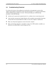
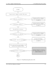
...the floppy disk drive, if installed, is unspecified, use an external FDD to run the diagnostics tests 2-2 Tecra A3/S2 Series Maintenance Manual Operating systems that Toshiba Windows XP is installed, you know the location of the malfunction, turn directly to the appropriate section of this... z Make sure all optional equipment is , ask him or her to enter the password. 2 Troubleshooting Procedures 2.3 Power Supply Troubleshooting 2.2 Troubleshooting Flowchart If you should use the flowchart in Figure 2-1 as a guide for determining which troubleshooting procedures to execute.
...the floppy disk drive, if installed, is unspecified, use an external FDD to run the diagnostics tests 2-2 Tecra A3/S2 Series Maintenance Manual Operating systems that Toshiba Windows XP is installed, you know the location of the malfunction, turn directly to the appropriate section of this... z Make sure all optional equipment is , ask him or her to enter the password. 2 Troubleshooting Procedures 2.3 Power Supply Troubleshooting 2.2 Troubleshooting Flowchart If you should use the flowchart in Figure 2-1 as a guide for determining which troubleshooting procedures to execute.
Maintenance Manual
Page 38
... section 2.3 Turn the Pow er sw itch on Y es Is the Pow er O n LED on ? Y es A Perform diagnostics program . Is Toshiba W indow s being loaded? Figure 2-1 Troubleshooting flowchart (1/2) Tecra A3/S2 Series Maintenance Manual 2-3 2.3 Power Supply Troubleshooting 2 Troubleshooting Procedures START Connect the AC adapter to the D C-IN socket Is the DC-IN LED on ? Perform the...
... section 2.3 Turn the Pow er sw itch on Y es Is the Pow er O n LED on ? Y es A Perform diagnostics program . Is Toshiba W indow s being loaded? Figure 2-1 Troubleshooting flowchart (1/2) Tecra A3/S2 Series Maintenance Manual 2-3 2.3 Power Supply Troubleshooting 2 Troubleshooting Procedures START Connect the AC adapter to the D C-IN socket Is the DC-IN LED on ? Perform the...

Maintenance Manual
Page 39
Then run the diagnostics test program. Yes Is the diagnostics test loaded? 2 Troubleshooting Procedures A 2.3 Power Supply Troubleshooting Does typed characters appear correctly? No System is normal Perform the Keyboard No Troubleshooting procedures in section 2.6 Perform the FDD No Troubleshooting procedures in... as outlined below. Yes Allow each test to perform automatically Is an error detected by any of the diagnostics tests? End Figure 2-1 Troubleshooting flowchart (2/2) 2-4 Tecra A3/S2 Series Maintenance Manual Yes Insert the diagnostics disk into the FDD.
Then run the diagnostics test program. Yes Is the diagnostics test loaded? 2 Troubleshooting Procedures A 2.3 Power Supply Troubleshooting Does typed characters appear correctly? No System is normal Perform the Keyboard No Troubleshooting procedures in section 2.6 Perform the FDD No Troubleshooting procedures in... as outlined below. Yes Allow each test to perform automatically Is an error detected by any of the diagnostics tests? End Figure 2-1 Troubleshooting flowchart (2/2) 2-4 Tecra A3/S2 Series Maintenance Manual Yes Insert the diagnostics disk into the FDD.

Maintenance Manual
Page 40
...should be intermittent. If an error is detected by the TouchPad test, perform the TouchPad Troubleshooting procedures in Section 2.5. 4. Tecra A3/S2 Series Maintenance Manual 2-5 If an error is detected by the keyboard test, perform the Keyboard Troubleshooting procedures in Section ... is detected by the printer (parallel) port test, perform the Printer Port Troubleshooting procedures in Section 2.12. 7. 2.3 Power Supply Troubleshooting 2 Troubleshooting Procedures If the diagnostics program cannot detect an error, the problem may be executed several times to isolate the...
...should be intermittent. If an error is detected by the TouchPad test, perform the TouchPad Troubleshooting procedures in Section 2.5. 4. Tecra A3/S2 Series Maintenance Manual 2-5 If an error is detected by the keyboard test, perform the Keyboard Troubleshooting procedures in Section ... is detected by the printer (parallel) port test, perform the Printer Port Troubleshooting procedures in Section 2.12. 7. 2.3 Power Supply Troubleshooting 2 Troubleshooting Procedures If the diagnostics program cannot detect an error, the problem may be executed several times to isolate the...

Maintenance Manual
Page 41
2 Troubleshooting Procedures 2.3 Power Supply Troubleshooting Other problems that are not covered by the diagnostics program may be discovered by a user. 1. If an error is detected when using the Wireless LAN, perform the Wireless LAN Troubleshooting procedures in Section 2.15. 2-6 Tecra A3/S2 Series Maintenance Manual If an error is detected when using the IEEE1394 device...
2 Troubleshooting Procedures 2.3 Power Supply Troubleshooting Other problems that are not covered by the diagnostics program may be discovered by a user. 1. If an error is detected when using the Wireless LAN, perform the Wireless LAN Troubleshooting procedures in Section 2.15. 2-6 Tecra A3/S2 Series Maintenance Manual If an error is detected when using the IEEE1394 device...
Maintenance Manual
Page 42
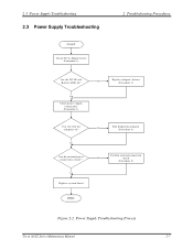
Y es Replace system board Y es Run diagnostic program (Procedure 4) Perform internal connection No check (Procedure 5) END Figure 2-2 Power Supply Troubleshooting Process Tecra A3/S2 Series Maintenance Manual 2-7 Y es Check power supply connections (Procedure 3) No Replace adaptor / battery (Procedure 2) Can you turn the computer on? 2.3 Power Supply Troubleshooting 2.3 Power Supply Troubleshooting START Check Power Supply Status (Procedure 1) 2 Troubleshooting Procedures Are the DC-IN and Battery LEDs lit? No Are the internal power connections secure?
Y es Replace system board Y es Run diagnostic program (Procedure 4) Perform internal connection No check (Procedure 5) END Figure 2-2 Power Supply Troubleshooting Process Tecra A3/S2 Series Maintenance Manual 2-7 Y es Check power supply connections (Procedure 3) No Replace adaptor / battery (Procedure 2) Can you turn the computer on? 2.3 Power Supply Troubleshooting 2.3 Power Supply Troubleshooting START Check Power Supply Status (Procedure 1) 2 Troubleshooting Procedures Are the DC-IN and Battery LEDs lit? No Are the internal power connections secure?
Maintenance Manual
Page 43
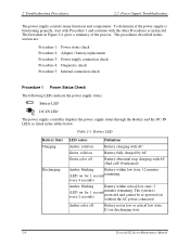
... procedures described in discharging state 2-8 Tecra A3/S2 Series Maintenance Manual Green, solid on Battery fully charged by AC Green color off Battery not in Figure 2-2 gives a summary of the process. The system is functioning properly, start with Procedure 1 and continue with AC . 2 Troubleshooting Procedures 2.3 Power Supply Troubleshooting The power supply controls many functions and components...
... procedures described in discharging state 2-8 Tecra A3/S2 Series Maintenance Manual Green, solid on Battery fully charged by AC Green color off Battery not in Figure 2-2 gives a summary of the process. The system is functioning properly, start with Procedure 1 and continue with AC . 2 Troubleshooting Procedures 2.3 Power Supply Troubleshooting The power supply controls many functions and components...
Maintenance Manual
Page 44
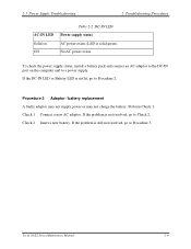
... (LED is still not resolved, go to Procedure 3. Check 2 Insert a new battery. Tecra A3/S2 Series Maintenance Manual 2-9 Procedure 2 Adaptor / battery replacement A faulty adaptor may not supply power or may not charge the battery. No AC power exists. Check 1 Connect a new AC adaptor. 2.3 Power Supply Troubleshooting 2 Troubleshooting Procedures AC-IN LED Solid on the computer and to...
... (LED is still not resolved, go to Procedure 3. Check 2 Insert a new battery. Tecra A3/S2 Series Maintenance Manual 2-9 Procedure 2 Adaptor / battery replacement A faulty adaptor may not supply power or may not charge the battery. No AC power exists. Check 1 Connect a new AC adaptor. 2.3 Power Supply Troubleshooting 2 Troubleshooting Procedures AC-IN LED Solid on the computer and to...


