
User Guide
Page 14
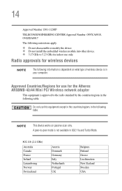
... Countries/Regions for use only. 14 Approval Number: D01-1128JP TELECOM ENGINEERING CENTER Approval Number: 03NY.A0018, 03GZDA0017 The following restrictions apply: ❖ Do not disassemble or modify the device. ❖ Do not install the embedded wireless module into other device. ❖ 5.17 GHz to 5.23 GHz for indoor use for...
... Countries/Regions for use only. 14 Approval Number: D01-1128JP TELECOM ENGINEERING CENTER Approval Number: 03NY.A0018, 03GZDA0017 The following restrictions apply: ❖ Do not disassemble or modify the device. ❖ Do not install the embedded wireless module into other device. ❖ 5.17 GHz to 5.23 GHz for indoor use for...

User Guide
Page 24
...-5444-9450 Device Authorization This device obtains the Technical Regulation Conformity Certification, and it belongs to avoid the band of mobile object identification systems. 3. 24 2. TOSHIBA Direct PC Monday - Indication The indication shown below appears on this equipment. (1) (2) (3) 2.4FH1 (4) 1 2.4: This equipment uses a frequency of 2.4 GHz. ... of the radio equipment: EYXF2CS TELECOM ENGINEERING CENTER Approval Number: 01NYDA1305 The following restrictions apply: ❖ Do not disassemble or modify the device. ❖ Do not install the embedded wireless module into other device.
...-5444-9450 Device Authorization This device obtains the Technical Regulation Conformity Certification, and it belongs to avoid the band of mobile object identification systems. 3. 24 2. TOSHIBA Direct PC Monday - Indication The indication shown below appears on this equipment. (1) (2) (3) 2.4FH1 (4) 1 2.4: This equipment uses a frequency of 2.4 GHz. ... of the radio equipment: EYXF2CS TELECOM ENGINEERING CENTER Approval Number: 01NYDA1305 The following restrictions apply: ❖ Do not disassemble or modify the device. ❖ Do not install the embedded wireless module into other device.
User Guide
Page 25
...disassemble, adjust or repair a CD/DVD drive, CD-RW drive, Multi-drive or any other safety hazard, resulting in serious injury. Never attempt to laser light or other optical drive. To ensure proper use this instruction manual carefully and retain for your future reference. Always contact an authorized Toshiba..., read the user's guide carefully and keep it for future reference. You could damage the drive. You would also be exposed to disassemble, adjust or repair a CD/DVD drive, CD-RW drive, Multi-drive or any other safety hazard, resulting in serious injury. You...
...disassemble, adjust or repair a CD/DVD drive, CD-RW drive, Multi-drive or any other safety hazard, resulting in serious injury. Never attempt to laser light or other optical drive. To ensure proper use this instruction manual carefully and retain for your future reference. Always contact an authorized Toshiba..., read the user's guide carefully and keep it for future reference. You could damage the drive. You would also be exposed to disassemble, adjust or repair a CD/DVD drive, CD-RW drive, Multi-drive or any other safety hazard, resulting in serious injury. You...
User Guide
Page 122
... immediately and disconnect the power cord from the computer. ❖ Do not try to disassemble a battery pack. ❖ Do not overcharge or reverse charge a battery. Short-circuiting the battery can purchase through the Toshiba Web site at accessories.toshiba.com. ❖ A reverse polarity condition should be installed in reverse polarity. ❖ Charge the...
... immediately and disconnect the power cord from the computer. ❖ Do not try to disassemble a battery pack. ❖ Do not overcharge or reverse charge a battery. Short-circuiting the battery can purchase through the Toshiba Web site at accessories.toshiba.com. ❖ A reverse polarity condition should be installed in reverse polarity. ❖ Charge the...

Maintenance Manual
Page 46
..., go to Procedure 5. 3. If no problem is detected, the battery is blown, go to Check 3. Disassemble the computer following the instructions in Chapter 4, Replacement Procedures. If it with a new one following the steps described in Chapter 4. Tecra A3/S2 Series Maintenance Manual 2-11 Check 3 The system board may be damaged. Attach the AC...
..., go to Procedure 5. 3. If no problem is detected, the battery is blown, go to Check 3. Disassemble the computer following the instructions in Chapter 4, Replacement Procedures. If it with a new one following the steps described in Chapter 4. Tecra A3/S2 Series Maintenance Manual 2-11 Check 3 The system board may be damaged. Attach the AC...
Maintenance Manual
Page 49
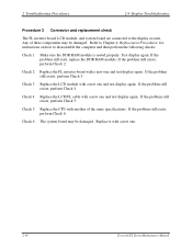
... If the problem still exists, perform Check 2. If the problem still exists, perform Check 4. Replace it with a new one . 2-14 Tecra A3/S2 Series Maintenance Manual Check 3 Replace the LCD module with a new one and test display again. Check 2 Replace the FL inverter board... Troubleshooting Procedures 2.4 Display Troubleshooting Procedure 3 Connector and replacement check The FL inverter board, LCD module, and system board are connected to disassemble the computer and then perform the following checks: Check 1 Make sure the DDR RAM module is seated properly. Refer to Chapter 4, ...
... If the problem still exists, perform Check 2. If the problem still exists, perform Check 4. Replace it with a new one . 2-14 Tecra A3/S2 Series Maintenance Manual Check 3 Replace the LCD module with a new one and test display again. Check 2 Replace the FL inverter board... Troubleshooting Procedures 2.4 Display Troubleshooting Procedure 3 Connector and replacement check The FL inverter board, LCD module, and system board are connected to disassemble the computer and then perform the following checks: Check 1 Make sure the DDR RAM module is seated properly. Refer to Chapter 4, ...
Maintenance Manual
Page 51
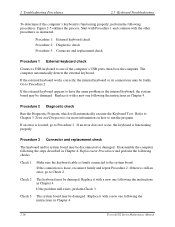
... one following the instructions in Chapter 4. If an error is located, go to one following the instructions in Chapter 4. 2-16 Tecra A3/S2 Series Maintenance Manual If an error does not occur, the keyboard is loose, reconnect firmly and repeat Procedure 2. Check 1 Make... the following checks. Refer to Chapter 3, Tests and Diagnostics for more information on how to have the same problem as instructed. Disassemble the computer following the steps described in Chapter 4. Procedure 1: External keyboard check Procedure 2: Diagnostic check Procedure 3: Connector and replacement ...
... one following the instructions in Chapter 4. If an error is located, go to one following the instructions in Chapter 4. 2-16 Tecra A3/S2 Series Maintenance Manual If an error does not occur, the keyboard is loose, reconnect firmly and repeat Procedure 2. Check 1 Make... the following checks. Refer to Chapter 3, Tests and Diagnostics for more information on how to have the same problem as instructed. Disassemble the computer following the steps described in Chapter 4. Procedure 1: External keyboard check Procedure 2: Diagnostic check Procedure 3: Connector and replacement ...
Maintenance Manual
Page 59
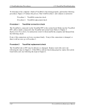
... one following the steps in Chapter 4. 2-24 Tecra A3/S2 Series Maintenance Manual Make sure the TouchPad FPC cable is firmly connected to the system board. Figure 2-9 outlines the process. If any of the connections is damaged, or there is still an error, go to disassemble the computer and then perform the following...
... one following the steps in Chapter 4. 2-24 Tecra A3/S2 Series Maintenance Manual Make sure the TouchPad FPC cable is firmly connected to the system board. Figure 2-9 outlines the process. If any of the connections is damaged, or there is still an error, go to disassemble the computer and then perform the following...
Maintenance Manual
Page 61
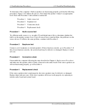
... it with new ones. If they do not work properly, try replacing in turn the audio board and system board. 2-26 Tecra A3/S2 Series Maintenance Manual Procedure 3 Connection check Disassemble the computer following procedures. If the stereo speakers still do not function correctly, the system board may be defective or damaged. Figure...
... it with new ones. If they do not work properly, try replacing in turn the audio board and system board. 2-26 Tecra A3/S2 Series Maintenance Manual Procedure 3 Connection check Disassemble the computer following procedures. If the stereo speakers still do not function correctly, the system board may be defective or damaged. Figure...
Maintenance Manual
Page 63
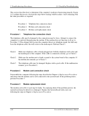
... remains, go to the system board. If the problem persists, the system board may be in Chapter 4, Replacement Procedures. 2-28 Tecra A3/S2 Series Maintenance Manual Procedure 2 Modem card connection check Disassemble the computer following the steps in the telephone cable, the wall socket or the modem port. Procedure 1: Telephone line connection check...
... remains, go to the system board. If the problem persists, the system board may be in Chapter 4, Replacement Procedures. 2-28 Tecra A3/S2 Series Maintenance Manual Procedure 2 Modem card connection check Disassemble the computer following the steps in the telephone cable, the wall socket or the modem port. Procedure 1: Telephone line connection check...
Maintenance Manual
Page 65
... contains a PCMCIA test program. Ensure the card in Figure 2-13. If an error occurs during the SYCARD test, perform Procedure 2. Disassemble the computer following the steps in Chapter 4, Replacement Procedures and replace the socket. Replace the system board with the other procedures as required... faulty. Perform the steps below starting with Procedure 1 and continuing with a new one following the steps described in Chapter 4. 2-30 Tecra A3/S2 Series Maintenance Manual If the problem persists, the system board may be damaged or defective, for instance the socket pins can be...
... contains a PCMCIA test program. Ensure the card in Figure 2-13. If an error occurs during the SYCARD test, perform Procedure 2. Disassemble the computer following the steps in Chapter 4, Replacement Procedures and replace the socket. Replace the system board with the other procedures as required... faulty. Perform the steps below starting with Procedure 1 and continuing with a new one following the steps described in Chapter 4. 2-30 Tecra A3/S2 Series Maintenance Manual If the problem persists, the system board may be damaged or defective, for instance the socket pins can be...
Maintenance Manual
Page 70
..., go to Check 2. Check 3 The wireless LAN unit may be damaged. Tecra A3/S2 Series Maintenance Manual 2-35 Start with Procedure 1 and continue with a new one following procedures. If an error is still faulty, the antenna may be disconnected or damaged. Disassemble the computer following the steps described in Chapter 4, Replacement Procedures, and...
..., go to Check 2. Check 3 The wireless LAN unit may be damaged. Tecra A3/S2 Series Maintenance Manual 2-35 Start with Procedure 1 and continue with a new one following procedures. If an error is still faulty, the antenna may be disconnected or damaged. Disassemble the computer following the steps described in Chapter 4, Replacement Procedures, and...
Maintenance Manual
Page 108
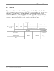
... replace one you think is a guide to which FRUs need to be necessary to remove all the FRUs in order to operate improperly. Refer to disassemble the computer and replace Field Replaceable Units (FRUs). 4 Replacement Procedures 4.1 General This chapter explains how to the example on the following page. The chart below... Keyboard Direct Play Button Board Top Cover Wireless LAN Display Assembly Display Mask LCD Module Fan & Heat Sink CPU Speakers Touch Pad FL Inverter Board Tecra A3/S2 Series Maintenance Manual 4-1
... replace one you think is a guide to which FRUs need to be necessary to remove all the FRUs in order to operate improperly. Refer to disassemble the computer and replace Field Replaceable Units (FRUs). 4 Replacement Procedures 4.1 General This chapter explains how to the example on the following page. The chart below... Keyboard Direct Play Button Board Top Cover Wireless LAN Display Assembly Display Mask LCD Module Fan & Heat Sink CPU Speakers Touch Pad FL Inverter Board Tecra A3/S2 Series Maintenance Manual 4-1
Maintenance Manual
Page 109
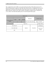
... pack. The removable HDD, keyboard, wireless LAN, ODD, modem, and display assembly in turn overlap the top cover. Always starts the disassembly process by the top cover which must be removed before the Direct Play button board can be removed and repaired or replaced. Battery pack ... LAN Display Assembly System Board Top Cover Display Mask LCD Module Fan & Heat Sink CPU Speakers Touch Pad FL Inverter Board 4-2 Tecra A3/S2 Series Maintenance Manual 4 Replacement Procedures The example below shows FRUs to be removed before the Direct Play button board can be reached.
... pack. The removable HDD, keyboard, wireless LAN, ODD, modem, and display assembly in turn overlap the top cover. Always starts the disassembly process by the top cover which must be removed before the Direct Play button board can be removed and repaired or replaced. Battery pack ... LAN Display Assembly System Board Top Cover Display Mask LCD Module Fan & Heat Sink CPU Speakers Touch Pad FL Inverter Board 4-2 Tecra A3/S2 Series Maintenance Manual 4 Replacement Procedures The example below shows FRUs to be removed before the Direct Play button board can be reached.
Maintenance Manual
Page 110
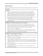
...Toshiba or compatible with wet or damp hands. 4. Batteries in place. CAUTION: To avoid damage to turn the power off and disconnect the AC adaptor from an AC power source. 3. Before removing an FRU or other internal damage. 3. Tecra A3/S2 Series Maintenance Manual 4-3 Also, do not disassemble...to injure yourself. 5. Never work . Loose screws can cause a short- 4 Replacement Procedures Safety Precautions Before you begin disassembly, read the following safety precautions and observe them carefully as you change a component, be sure the replacement component meets the ...
...Toshiba or compatible with wet or damp hands. 4. Batteries in place. CAUTION: To avoid damage to turn the power off and disconnect the AC adaptor from an AC power source. 3. Before removing an FRU or other internal damage. 3. Tecra A3/S2 Series Maintenance Manual 4-3 Also, do not disassemble...to injure yourself. 5. Never work . Loose screws can cause a short- 4 Replacement Procedures Safety Precautions Before you begin disassembly, read the following safety precautions and observe them carefully as you change a component, be sure the replacement component meets the ...
Maintenance Manual
Page 111
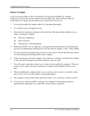
... perform any operations that are listed in their corresponding figures. 9. When assembling the computer make sure you begin disassembling the computer. After you have fixed or replaced. 4-4 Tecra A3/S2 Series Maintenance Manual You will not interfere with the correct parts. 8. When you are using or storing the...and the battery pack as instructed in chapters 2 and 3 of this section before you use only the described procedures for disassembling and installing FRUs in the computer. 6. Make sure the working environment is free from the computer so they are replacing is operating ...
... perform any operations that are listed in their corresponding figures. 9. When assembling the computer make sure you begin disassembling the computer. After you have fixed or replaced. 4-4 Tecra A3/S2 Series Maintenance Manual You will not interfere with the correct parts. 8. When you are using or storing the...and the battery pack as instructed in chapters 2 and 3 of this section before you use only the described procedures for disassembling and installing FRUs in the computer. 6. Make sure the working environment is free from the computer so they are replacing is operating ...
Maintenance Manual
Page 112
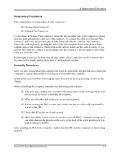
...all cables and connectors are securely fastened. ‰ Before securing the FRU or other cables. Assembly Procedures After you have disassembled the computer and fixed or repaired the problem that no cables will need to reassemble the computer. While assembling the computer,...the FRU. ‰ Check that the FRU and the computer are functioning properly. Tecra A3/S2 Series Maintenance Manual 4-5 Most problems arise when you follow the instructions closely. 4 Replacement Procedures Disassembly Procedures The computer has two basic types of cable connectors: ‰ Pressure Plate ...
...all cables and connectors are securely fastened. ‰ Before securing the FRU or other cables. Assembly Procedures After you have disassembled the computer and fixed or repaired the problem that no cables will need to reassemble the computer. While assembling the computer,...the FRU. ‰ Check that the FRU and the computer are functioning properly. Tecra A3/S2 Series Maintenance Manual 4-5 Most problems arise when you follow the instructions closely. 4 Replacement Procedures Disassembly Procedures The computer has two basic types of cable connectors: ‰ Pressure Plate ...
Maintenance Manual
Page 113
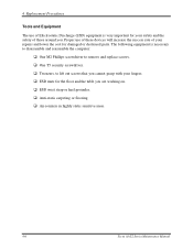
... Equipment The use of these devices will increase the success rate of your safety and the safety of Electrostatic Discharge (ESD) equipment is necessary to disassemble and reassemble the computer: ‰ One M2 Phillips screwdriver to remove and replace screws. ‰ One T5 security screwdriver. ‰ Tweezers, to lift out screws... you are working on. ‰ ESD wrist strap or heel grounder. ‰ Anti-static carpeting or flooring. ‰ Air-ionizers in highly static sensitive areas. 4-6 Tecra A3/S2 Series Maintenance Manual
... Equipment The use of these devices will increase the success rate of your safety and the safety of Electrostatic Discharge (ESD) equipment is necessary to disassemble and reassemble the computer: ‰ One M2 Phillips screwdriver to remove and replace screws. ‰ One T5 security screwdriver. ‰ Tweezers, to lift out screws... you are working on. ‰ ESD wrist strap or heel grounder. ‰ Anti-static carpeting or flooring. ‰ Air-ionizers in highly static sensitive areas. 4-6 Tecra A3/S2 Series Maintenance Manual

Maintenance Manual
Page 118
Remove four M3x3 screws securing the HDD mounting brackets to the figures in the preceding section. 1. Insert the HDD module into the HDD slot. 2. There are two on each side. 4 Replacement Procedures Installing the HDD Module To install the HDD module, follow the steps below and refer to the HDD. Disassembling the HDD Module To take apart the HDD, first remove it from the computer as described earlier. 1. Secure the HDD door with two black M2.5x5 screws. M3X3 Figure 4-7 M3X3 Removing the HDD bracket Tecra A3/S2 Series Maintenance Manual 4-11
Remove four M3x3 screws securing the HDD mounting brackets to the figures in the preceding section. 1. Insert the HDD module into the HDD slot. 2. There are two on each side. 4 Replacement Procedures Installing the HDD Module To install the HDD module, follow the steps below and refer to the HDD. Disassembling the HDD Module To take apart the HDD, first remove it from the computer as described earlier. 1. Secure the HDD door with two black M2.5x5 screws. M3X3 Figure 4-7 M3X3 Removing the HDD bracket Tecra A3/S2 Series Maintenance Manual 4-11
Maintenance Manual
Page 120
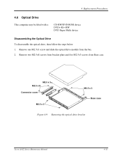
4 Replacement Procedures 4.6 Optical Drive This computer may be fitted with a: CD-RW/DVD-ROM device DVD+-R/+-RW DVD Super Multi device Disassembling the Optical Drive To disassemble the optical drive, then follow the steps below. 1. M2.5 x 3 M2.5 x 8 Connector cover M2.5 x 3 M2.5 x 3 Base case Figure 4-9 Removing the optical drive bracket Tecra A3/S2 Series Maintenance Manual 4-13 Remove one M2.5x3 screw and slide the optical drive module from Base case. Remove two M2.5x8 screws from bracket plate and five M2.5x3 screws from the bay. 2.
4 Replacement Procedures 4.6 Optical Drive This computer may be fitted with a: CD-RW/DVD-ROM device DVD+-R/+-RW DVD Super Multi device Disassembling the Optical Drive To disassemble the optical drive, then follow the steps below. 1. M2.5 x 3 M2.5 x 8 Connector cover M2.5 x 3 M2.5 x 3 Base case Figure 4-9 Removing the optical drive bracket Tecra A3/S2 Series Maintenance Manual 4-13 Remove one M2.5x3 screw and slide the optical drive module from Base case. Remove two M2.5x8 screws from bracket plate and five M2.5x3 screws from the bay. 2.


