
Service Manual
Page 3
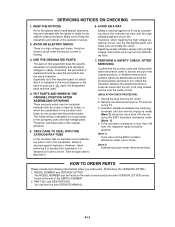
...such as a tube or tape for safety, or which need special attentions, they are assembled in this equipment have the specific characters of parts as to give a shock. Therefore, put in the circuit diagram or the table of incombustibility and withstand voltage for safety. Repairing except ...high voltage, and it emits an X-ray from the AC outlet. 2. A1-2 Avoid an electric shock while the electric current is a high voltage part inside wiring is secured against an X-ray by using the 500V insulation resistance meter [Note 1]. 4. However, when removing it or serving from backward...
...such as a tube or tape for safety, or which need special attentions, they are assembled in this equipment have the specific characters of parts as to give a shock. Therefore, put in the circuit diagram or the table of incombustibility and withstand voltage for safety. Repairing except ...high voltage, and it emits an X-ray from the AC outlet. 2. A1-2 Avoid an electric shock while the electric current is a high voltage part inside wiring is secured against an X-ray by using the 500V insulation resistance meter [Note 1]. 4. However, when removing it or serving from backward...
Service Manual
Page 4
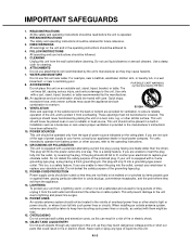
.... Use only with a polarized alternating-current line plug (a plug having a third (grounding) pin, this unit, as they may touch dangerous voltage points or short out parts that they exit from a lightning storm, or when it is equipped with care. GROUNDING OR POLARIZATION This unit is equipped with a cart, stand, tripod, bracket...
.... Use only with a polarized alternating-current line plug (a plug having a third (grounding) pin, this unit, as they may touch dangerous voltage points or short out parts that they exit from a lightning storm, or when it is equipped with care. GROUNDING OR POLARIZATION This unit is equipped with a cart, stand, tripod, bracket...

Service Manual
Page 5
... with high volume sound, it is closing. c. Adjust only those that the cable ground shall be sure the service technician uses replacement parts specified by following conditions: a. CONNECTING When you use a cracked, deformed, or repaired disc. A1-4 SERVICING Do not attempt to service... OUTDOOR ANTENNA GROUNDING If an outside antenna or cable system is connected to see the source of any connections. 26. REPLACEMENT PARTS When replacement parts are required, be connected to grounding electrodes, and requirements for service. 20. HEAT The product should be mounted to a ...
... with high volume sound, it is closing. c. Adjust only those that the cable ground shall be sure the service technician uses replacement parts specified by following conditions: a. CONNECTING When you use a cracked, deformed, or repaired disc. A1-4 SERVICING Do not attempt to service... OUTDOOR ANTENNA GROUNDING If an outside antenna or cable system is connected to see the source of any connections. 26. REPLACEMENT PARTS When replacement parts are required, be connected to grounding electrodes, and requirements for service. 20. HEAT The product should be mounted to a ...
Service Manual
Page 6
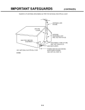
IMPORTANT SAFEGUARDS (CONTINUED) EXAMPLE OF ANTENNA GROUNDING AS PER THE NATIONAL ELECTRICAL CODE GROUND CLAMP ELECTRIC SERVICE EQUIPMENT NEC-NATIONAL ELECTRICAL CODE S2898A ANTENNA LEAD IN WIRE ANTENNA DISCHARGE UNIT (NEC SECTION 810-20) GROUNDING CONDUCTORS (NEC SECTION 810-21) GROUND CLAMPS POWER SERVICE GROUNDING ELECTRODE SYSTEM (NEC ART 250, PART H) A1-5
IMPORTANT SAFEGUARDS (CONTINUED) EXAMPLE OF ANTENNA GROUNDING AS PER THE NATIONAL ELECTRICAL CODE GROUND CLAMP ELECTRIC SERVICE EQUIPMENT NEC-NATIONAL ELECTRICAL CODE S2898A ANTENNA LEAD IN WIRE ANTENNA DISCHARGE UNIT (NEC SECTION 810-20) GROUNDING CONDUCTORS (NEC SECTION 810-21) GROUND CLAMPS POWER SERVICE GROUNDING ELECTRODE SYSTEM (NEC ART 250, PART H) A1-5

Service Manual
Page 11
... ...INTERCONNECTION DIAGRAM2 ...WAVEFORMS ...MECHANICAL EXPLODED VIEWS ...CHASSIS EXPLODED VIEWS ...DVD DECK EXPLODED VIEWS ...MECHANICAL REPLACEMENT PARTS LIST CHASSIS REPLACEMENT PARTS LIST DVD DECK REPLACEMENT PARTS LIST ELECTRICAL REPLACEMENT PARTS LIST A1-1 A1-2 A1-2 A1-3~A1-5 A1-6 A1-7 A1-7 A1-8 A1-8 A1-9 A2-1...I2-2 I3-1 J1-1, J1-2 J2-1 J3-1 J4-1~J4-11 A2-1 REMOVAL OF MECHANICAL PARTS AND P. TABLE OF CONTENTS CAUTION ...SERVICING NOTICES ON CHECKING ...HOW TO ORDER PARTS ...IMPORTANT SAFEGUARDS ...WHEN REPLACING DVD DECK ...TAPE REMOVAL METHOD AT NO POWER SUPPLY DISC REMOVAL ...
... ...INTERCONNECTION DIAGRAM2 ...WAVEFORMS ...MECHANICAL EXPLODED VIEWS ...CHASSIS EXPLODED VIEWS ...DVD DECK EXPLODED VIEWS ...MECHANICAL REPLACEMENT PARTS LIST CHASSIS REPLACEMENT PARTS LIST DVD DECK REPLACEMENT PARTS LIST ELECTRICAL REPLACEMENT PARTS LIST A1-1 A1-2 A1-2 A1-3~A1-5 A1-6 A1-7 A1-7 A1-8 A1-8 A1-9 A2-1...I2-2 I3-1 J1-1, J1-2 J2-1 J3-1 J4-1~J4-11 A2-1 REMOVAL OF MECHANICAL PARTS AND P. TABLE OF CONTENTS CAUTION ...SERVICING NOTICES ON CHECKING ...HOW TO ORDER PARTS ...IMPORTANT SAFEGUARDS ...WHEN REPLACING DVD DECK ...TAPE REMOVAL METHOD AT NO POWER SUPPLY DISC REMOVAL ...
Service Manual
Page 20
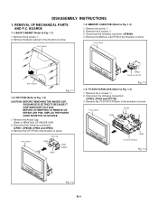
... 1-1: BACK CABINET (Refer to REMOVAL OF ANODE CAP) 2. Remove the CRT PCB in the direction of arrow. Disconnect the following connector: (CP9604). 4. REMOVAL OF MECHANICAL PARTS AND P.C. Remove the Memory Card PCB in the direction of arrow. Front Cabinet CRT PCB CP852 CP803 CP802B CP801 2 21 2 2 CP9604 Memory Card PCB Fig...
... 1-1: BACK CABINET (Refer to REMOVAL OF ANODE CAP) 2. Remove the CRT PCB in the direction of arrow. Disconnect the following connector: (CP9604). 4. REMOVAL OF MECHANICAL PARTS AND P.C. Remove the Memory Card PCB in the direction of arrow. Front Cabinet CRT PCB CP852 CP803 CP802B CP801 2 21 2 2 CP9604 Memory Card PCB Fig...

Service Manual
Page 24
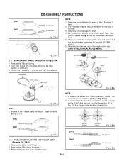
... (B) side. Extend the 2 supports 1. 2. Remove the Link Lever. 3. DISASSEMBLY INSTRUCTIONS 2. Remove the Cassette Side L. 2-3: LINK UNIT (Refer to the front side. 2. REMOVAL OF VCR DECK PARTS 2-1: TOP BRACKET (Refer to Fig. 2-1) 1. Remove the (A) side of the Top Bracket, bend the support 1 so that the Top Bracket is fixed.
... (B) side. Extend the 2 supports 1. 2. Remove the Link Lever. 3. DISASSEMBLY INSTRUCTIONS 2. Remove the Cassette Side L. 2-3: LINK UNIT (Refer to the front side. 2. REMOVAL OF VCR DECK PARTS 2-1: TOP BRACKET (Refer to Fig. 2-1) 1. Remove the (A) side of the Top Bracket, bend the support 1 so that the Top Bracket is fixed.
Service Manual
Page 26
... Arm Ass'y and Idler Gear. Unlock the 2 supports 1 and remove the T Brake Band. In case of the S Reel and T Reel installation, check if the correct parts are installed. (Refer to remove it . 5. Remove the 2 Polyslider Washers 1. 3. B2-3 Big Hole (S Reel) [OK] Clutch Gear [NG] Clutch Gear Small Hole (T Reel) Fig. 2-8-B Idler...
... Arm Ass'y and Idler Gear. Unlock the 2 supports 1 and remove the T Brake Band. In case of the S Reel and T Reel installation, check if the correct parts are installed. (Refer to remove it . 5. Remove the 2 Polyslider Washers 1. 3. B2-3 Big Hole (S Reel) [OK] Clutch Gear [NG] Clutch Gear Small Hole (T Reel) Fig. 2-8-B Idler...
Service Manual
Page 30
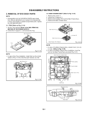
... the circled section of the Main Chassis Ass'y, install it from the Main Frame Ass'y. 4. Remove the screw 1. 2. Unlock the 2 supports 2. 3. REMOVAL OF DVD DECK PARTS NOTE 1. Main Frame Ass'y • Screw Torque: 2.0 ± 0.3kgf•cm Fig. 3-2-A NOTE 1. Minute adjustments are met. Main Frame Ass'y (Bottom Side) (3) Rack Loading (3)... Main Chassis Ass'y 1 Tray 1 Fig. 3-1-A NOTE 1. In case of Fig. 3-1-B so that the each markers are needed if the disassembly is needed except listed parts, replace the DVD MECHA ASS'Y. 3-1: TRAY (Refer to Fig. 3-2-B) 2.
... the circled section of the Main Chassis Ass'y, install it from the Main Frame Ass'y. 4. Remove the screw 1. 2. Unlock the 2 supports 2. 3. REMOVAL OF DVD DECK PARTS NOTE 1. Main Frame Ass'y • Screw Torque: 2.0 ± 0.3kgf•cm Fig. 3-2-A NOTE 1. Minute adjustments are met. Main Frame Ass'y (Bottom Side) (3) Rack Loading (3)... Main Chassis Ass'y 1 Tray 1 Fig. 3-1-A NOTE 1. In case of Fig. 3-1-B so that the each markers are needed if the disassembly is needed except listed parts, replace the DVD MECHA ASS'Y. 3-1: TRAY (Refer to Fig. 3-2-B) 2.
Service Manual
Page 34
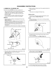
...one side of the Screwdriver. Location of Anode Cap GND on the Rubber Cap without moving any parts. Put on the CRT Fig. 4-3 2. B4-1 REMOVAL OF ANODE CAP Read the following NOTED...2. at the spot where the cap was located with the tip of the support. (Refer to the metal part of the Anode Cap and make sure to discharge the Anode Cap's potential voltage. * Do not use pliers... the Rubber Cap. Flip up the sides of the Rubber Cap in Fig. 4-5. While holding the plastic part of the insulated Screwdriver, touch the support of the Anode with a small amount of the Anode Support into...
...one side of the Screwdriver. Location of Anode Cap GND on the Rubber Cap without moving any parts. Put on the CRT Fig. 4-3 2. B4-1 REMOVAL OF ANODE CAP Read the following NOTED...2. at the spot where the cap was located with the tip of the support. (Refer to the metal part of the Anode Cap and make sure to discharge the Anode Cap's potential voltage. * Do not use pliers... the Rubber Cap. Flip up the sides of the Rubber Cap in Fig. 4-5. While holding the plastic part of the insulated Screwdriver, touch the support of the Anode with a small amount of the Anode Support into...
Service Manual
Page 35
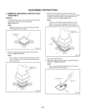
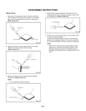
... Tape (Cotton Tape) 3. Heat the IC leads using a blower type IC desoldering machine. (Refer to Fig. 5-3.) NOTE Some ICs on all the parts located within 10 mm distance from IC leads. Absorb the solder left on the pattern using a tweezers and remove the IC by moving with the... B5-1 REMOVAL AND INSTALLATION OF FLAT PACKAGE IC REMOVAL 1. DISASSEMBLY INSTRUCTIONS 5. Put Masking Tape (cotton tape) around the Flat Package IC to protect other parts from any damage. (Refer to Fig. 5-1.) NOTE Masking is carried out on the PCB are affixed with glue, so be careful not to Fig. ...
... Tape (Cotton Tape) 3. Heat the IC leads using a blower type IC desoldering machine. (Refer to Fig. 5-3.) NOTE Some ICs on all the parts located within 10 mm distance from IC leads. Absorb the solder left on the pattern using a tweezers and remove the IC by moving with the... B5-1 REMOVAL AND INSTALLATION OF FLAT PACKAGE IC REMOVAL 1. DISASSEMBLY INSTRUCTIONS 5. Put Masking Tape (cotton tape) around the Flat Package IC to protect other parts from any damage. (Refer to Fig. 5-1.) NOTE Masking is carried out on the PCB are affixed with glue, so be careful not to Fig. ...
Service Manual
Page 36
... upper position to Fig. 5-6.) Fig. 5-8 5. Solder Soldering Iron IC Supply soldering from the upper position of IC leads sliding to the lower position of the parts around the IC. If some abnormality is found , correct by resoldering. So, always be damaged. Finally, confirm the soldering status on four sides of leads...
... upper position to Fig. 5-6.) Fig. 5-8 5. Solder Soldering Iron IC Supply soldering from the upper position of IC leads sliding to the lower position of the parts around the IC. If some abnormality is found , correct by resoldering. So, always be damaged. Finally, confirm the soldering status on four sides of leads...

Service Manual
Page 40
...the confirmation of notation. PREVENTIVE CHECKS AND SERVICE INTERVALS The following list means standard hours, so the checking hours depends on the conditions. Time Parts Name Audio Control Head Full Erase Head (Recorder only) Capstan Belt Pinch Roller Capstan DD Unit Loading Motor Tension Band T Brake Band Clutch...Idler Arm Ass'y Capstan Shaft Tape Running Guide Post Cylinder Unit 500 hours 1,000 hours 1,500 hours 2,000 hours 2,500 hours Notes Clean those parts in 16 system of using hours, turn off the power. Clean the Head : Clean : Check it and if necessary, replace it. Set...
...the confirmation of notation. PREVENTIVE CHECKS AND SERVICE INTERVALS The following list means standard hours, so the checking hours depends on the conditions. Time Parts Name Audio Control Head Full Erase Head (Recorder only) Capstan Belt Pinch Roller Capstan DD Unit Loading Motor Tension Band T Brake Band Clutch...Idler Arm Ass'y Capstan Shaft Tape Running Guide Post Cylinder Unit 500 hours 1,000 hours 1,500 hours 2,000 hours 2,500 hours Notes Clean those parts in 16 system of using hours, turn off the power. Clean the Head : Clean : Check it and if necessary, replace it. Set...

Service Manual
Page 53
... so that they have no short-circuit each other. 2. D1-1 Remove the TV/DVD/VCR Block from the set. Be sure to place the parts on Playback PREPARATION FOR SERVICING How to use the Servicing Fixture 1. APJG002B00 APJG002E00 APJG002F00 APJG022000 APJG024A00 APJG153000 APJG154000 APJG185000... Parts Name Adapter Dial Torque Gauge (10~90gf•cm) Dial Torque Gauge (60~600gf•cm) Master Plane Reel Disk Height Adjustment Jig X ...
... so that they have no short-circuit each other. 2. D1-1 Remove the TV/DVD/VCR Block from the set. Be sure to place the parts on Playback PREPARATION FOR SERVICING How to use the Servicing Fixture 1. APJG002B00 APJG002E00 APJG002F00 APJG022000 APJG024A00 APJG153000 APJG154000 APJG185000... Parts Name Adapter Dial Torque Gauge (10~90gf•cm) Dial Torque Gauge (60~600gf•cm) Master Plane Reel Disk Height Adjustment Jig X ...
Service Manual
Page 55
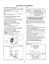
...~180gf•cm. Adjustment is on the remote control more than 3 : 2 as usual. Connect CH-1 of the range, replace the following parts. Even if you press the Tracking Button to move the envelope (The envelope waveform will be flat. Once set to the Fast Forward mode then...T Reel. 3. Turn the Torque Gauge (JG002F) clockwise. 4. Once set to the Fast Forward mode then set to decrease when you replace the parts of the tape running mechanism because of long term usage or failure, the confirmation and adjustment are necessary. 2-1: GUIDE ROLLER 1. Check item Replacement...
...~180gf•cm. Adjustment is on the remote control more than 3 : 2 as usual. Connect CH-1 of the range, replace the following parts. Even if you press the Tracking Button to move the envelope (The envelope waveform will be flat. Once set to the Fast Forward mode then...T Reel. 3. Turn the Torque Gauge (JG002F) clockwise. 4. Once set to the Fast Forward mode then set to decrease when you replace the parts of the tape running mechanism because of long term usage or failure, the confirmation and adjustment are necessary. 2-1: GUIDE ROLLER 1. Check item Replacement...
Service Manual
Page 58
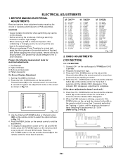
... the options shown in Fig. 1-1. (VCR SECTION) 2-1: PG SHIFTER 1. BEFORE MAKING ELECTRICAL ADJUSTMENTS Read and perform these adjustments when repairing the circuits or replacing electrical parts or PCB assemblies. BASIC ADJUSTMENTS Prepare the following measurement tools for a heat sink, apply the silicon grease on the screen as shown in Fig. 1-2. 4. DOWN...
... the options shown in Fig. 1-1. (VCR SECTION) 2-1: PG SHIFTER 1. BEFORE MAKING ELECTRICAL ADJUSTMENTS Read and perform these adjustments when repairing the circuits or replacing electrical parts or PCB assemblies. BASIC ADJUSTMENTS Prepare the following measurement tools for a heat sink, apply the silicon grease on the screen as shown in Fig. 1-2. 4. DOWN...
Service Manual
Page 64
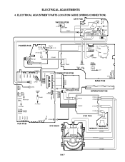
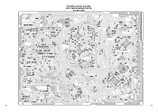
ELECTRICAL ADJUSTMENTS 4. ELECTRICAL ADJUSTMENT PARTS LOCATION GUIDE (WIRING CONNECTION) VM COIL PCB CP853 S853 S854 CD852 CRT PCB R841 TP806 CP852 CP804 TP805 R834 J801 CP803 CRT TP804 R801 CP808B ...
ELECTRICAL ADJUSTMENTS 4. ELECTRICAL ADJUSTMENT PARTS LOCATION GUIDE (WIRING CONNECTION) VM COIL PCB CP853 S853 S854 CD852 CRT PCB R841 TP806 CP852 CP804 TP805 R834 J801 CP803 CRT TP804 R801 CP808B ...
Service Manual
Page 83
... C4226 C4230 C4227 C4236 R006 C008 R312 R302 Q350 C002 R001 R002 R004 R005 C006 C320 C324 C313 C332 PRINTED CIRCUIT BOARDS VCR (CHIP MOUNTED PARTS) SOLDER SIDE R1002 R8021 R8023 R8025 R8020 Q3012 Q3006 R8047 R8027 C8017 R3007 R3009 Q3001 C8025 C8090 IC8004 R8056 R8051 R8026 R8054 C8077 C8070 R8048...
... C4226 C4230 C4227 C4236 R006 C008 R312 R302 Q350 C002 R001 R002 R004 R005 C006 C320 C324 C313 C332 PRINTED CIRCUIT BOARDS VCR (CHIP MOUNTED PARTS) SOLDER SIDE R1002 R8021 R8023 R8025 R8020 Q3012 Q3006 R8047 R8027 C8017 R3007 R3009 Q3001 C8025 C8090 IC8004 R8056 R8051 R8026 R8054 C8077 C8070 R8048...
Service Manual
Page 86
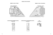
R9604 W803 R9607 W804 MEMORY CARD (TOP SIDE) PRINTED CIRCUIT BOARDS R9651 R9650 R9649 R9648 DED022A R9647 R9646 R9645 R9644 C9603 R9653 R9654 Q9601 Q9602 R9619 R9637 R9613 CP9603 R9617 W806 W805 R9614 R9635 CP9604 R9634 R9643 R9642 R9641 R9640 R9610 R9603 B9601 C9605 C9604 MEMORY CARD ( BOTTOM SIDE) DED022A R9639 R9636 R9638 R9601 R9611 R9612 R9609 R9608 R9652 SW1 LOADING MOTOR (INSERTED PARTS) SOLDER SIDE LOADING MOTOR (CHIP MOUNTED PARTS) SOLDER SIDE SW SOLDER SIDE BL GR OR YE SW2 CD2301 M2602 M2601 F-13 CD2302 F-14
R9604 W803 R9607 W804 MEMORY CARD (TOP SIDE) PRINTED CIRCUIT BOARDS R9651 R9650 R9649 R9648 DED022A R9647 R9646 R9645 R9644 C9603 R9653 R9654 Q9601 Q9602 R9619 R9637 R9613 CP9603 R9617 W806 W805 R9614 R9635 CP9604 R9634 R9643 R9642 R9641 R9640 R9610 R9603 B9601 C9605 C9604 MEMORY CARD ( BOTTOM SIDE) DED022A R9639 R9636 R9638 R9601 R9611 R9612 R9609 R9608 R9652 SW1 LOADING MOTOR (INSERTED PARTS) SOLDER SIDE LOADING MOTOR (CHIP MOUNTED PARTS) SOLDER SIDE SW SOLDER SIDE BL GR OR YE SW2 CD2301 M2602 M2601 F-13 CD2302 F-14
Service Manual
Page 87
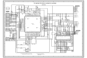
...+ TRFO+ FO- 1 NOTE: THIS SCHEMATIC DIAGRAM IS THE LATEST AT THE TIME OF PRINTING AND SUBJECT TO CHANGE WITHOUT NOTICE NOTE:THE DC VOLTAGE EACH PART WAS MEASURED WITH THE DIGITAL TESTER DURING PLAYBACK. A B C G-1 D E F G H 8 7 6 5 4 3 2 1 G-2 JG063 R2653 100 R2652 100 MOT_LDMOT_LD+ TOUT_SW TIN_SW JG053 JG054 P.CON+3.3V OPU_B OPU_C OPU_D OPU_A 0 NC...
...+ TRFO+ FO- 1 NOTE: THIS SCHEMATIC DIAGRAM IS THE LATEST AT THE TIME OF PRINTING AND SUBJECT TO CHANGE WITHOUT NOTICE NOTE:THE DC VOLTAGE EACH PART WAS MEASURED WITH THE DIGITAL TESTER DURING PLAYBACK. A B C G-1 D E F G H 8 7 6 5 4 3 2 1 G-2 JG063 R2653 100 R2652 100 MOT_LDMOT_LD+ TOUT_SW TIN_SW JG053 JG054 P.CON+3.3V OPU_B OPU_C OPU_D OPU_A 0 NC...


