
Service Manual
Page 5
... service personnel. 19. OUTDOOR ANTENNA GROUNDING If an outside antenna or cable system is connected to the minimum level before you use a cracked, deformed, or repaired disc. Read the owner's manual of the equipment from heat sources such as radiators, heat registers, stoves, or other products (including amplifiers) that the cable ground shall be situated away from the wall outlet. SOUND VOLUME...
... service personnel. 19. OUTDOOR ANTENNA GROUNDING If an outside antenna or cable system is connected to the minimum level before you use a cracked, deformed, or repaired disc. Read the owner's manual of the equipment from heat sources such as radiators, heat registers, stoves, or other products (including amplifiers) that the cable ground shall be situated away from the wall outlet. SOUND VOLUME...
Service Manual
Page 6
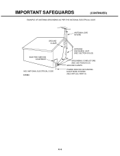
IMPORTANT SAFEGUARDS (CONTINUED) EXAMPLE OF ANTENNA GROUNDING AS PER THE NATIONAL ELECTRICAL CODE GROUND CLAMP ELECTRIC SERVICE EQUIPMENT NEC-NATIONAL ELECTRICAL CODE S2898A ANTENNA LEAD IN WIRE ANTENNA DISCHARGE UNIT (NEC SECTION 810-20) GROUNDING CONDUCTORS (NEC SECTION 810-21) GROUND CLAMPS POWER SERVICE GROUNDING ELECTRODE SYSTEM (NEC ART 250, PART H) A1-5
IMPORTANT SAFEGUARDS (CONTINUED) EXAMPLE OF ANTENNA GROUNDING AS PER THE NATIONAL ELECTRICAL CODE GROUND CLAMP ELECTRIC SERVICE EQUIPMENT NEC-NATIONAL ELECTRICAL CODE S2898A ANTENNA LEAD IN WIRE ANTENNA DISCHARGE UNIT (NEC SECTION 810-20) GROUNDING CONDUCTORS (NEC SECTION 810-21) GROUND CLAMPS POWER SERVICE GROUNDING ELECTRODE SYSTEM (NEC ART 250, PART H) A1-5
Service Manual
Page 9
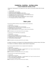
... be opened by setting the Tray Lock, please follow the steps below . 1. NOTE: No indications on the front panel. 4. The 4 digit password has now been cleared. Press and hold the 'STOP(DVD)' button on the screen when the Tray Lock is setting. Set the DVD to the Stop Mode. 3. PARENTAL CONTROL - Set the DVD to check the Tray Lock setting. Hold both keys for more than 2 seconds. 7. Press it in order of 'SETUP', 'SUBTITLE', '3', 'AUDIO SELECT' and '0' key of a remote control...
... be opened by setting the Tray Lock, please follow the steps below . 1. NOTE: No indications on the front panel. 4. The 4 digit password has now been cleared. Press and hold the 'STOP(DVD)' button on the screen when the Tray Lock is setting. Set the DVD to the Stop Mode. 3. PARENTAL CONTROL - Set the DVD to check the Tray Lock setting. Hold both keys for more than 2 seconds. 7. Press it in order of 'SETUP', 'SUBTITLE', '3', 'AUDIO SELECT' and '0' key of a remote control...

Service Manual
Page 11
... ...PRINTED CIRCUIT BOARDS DVD ...MAIN/CRT/OPERATION/CONNECTOR/VM COIL VCR ...HD-MI/SCALER ...POWER ...MEMORY CARD/LOADING MOTOR/SW SCHEMATIC DIAGRAMS RF AMP/MOTOR DRIVE ...MPEG/MICON ...MEMORY ...MEMORY CARD1 ...AUDIO/JACK ...MEMORY CARD2 ...Y/C/AUDIO/HEAD AMP ...SYSCON/SERVO/TIMER ...REGULATOR ...IN/OUT ...SOUND AMP/SURROUND ...Hi-Fi ...TUNER/AV ...CHROMA/PROGRESSIVE/PIN CUSHION TV MICON ...SYNC COUNT/CONNECTOR ...ANALOG/DIGITAL CONVERTER ...SCALER ...DIGITAL COMB ...SDRAM...
... ...PRINTED CIRCUIT BOARDS DVD ...MAIN/CRT/OPERATION/CONNECTOR/VM COIL VCR ...HD-MI/SCALER ...POWER ...MEMORY CARD/LOADING MOTOR/SW SCHEMATIC DIAGRAMS RF AMP/MOTOR DRIVE ...MPEG/MICON ...MEMORY ...MEMORY CARD1 ...AUDIO/JACK ...MEMORY CARD2 ...Y/C/AUDIO/HEAD AMP ...SYSCON/SERVO/TIMER ...REGULATOR ...IN/OUT ...SOUND AMP/SURROUND ...Hi-Fi ...TUNER/AV ...CHROMA/PROGRESSIVE/PIN CUSHION TV MICON ...SYNC COUNT/CONNECTOR ...ANALOG/DIGITAL CONVERTER ...SCALER ...DIGITAL COMB ...SDRAM...
Service Manual
Page 12
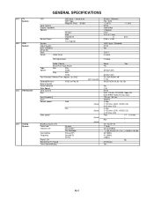
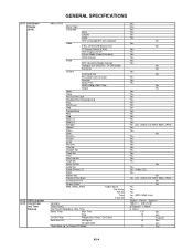
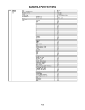
... G-2 VCR System G-3 DVD System G-4 Tuning System GENERAL SPECIFICATIONS CRT Color System Display Capability Speaker Sound Output System Video System Hi-Fi STEREO NTSC PB Deck Heads Video Head CRT Size / Visual Size CRT Type Magnetic Field BV/BH Position Size Impedance MAX 10%(Typical) FM Audio Head Audio /Control Erase(Full Track Erase) Tape Rec PAL Speed NTSC Play PAL NTSC Fast Forward / Rewind Time (Approx.) at 25oC Forward/Reverse Picture...
... G-2 VCR System G-3 DVD System G-4 Tuning System GENERAL SPECIFICATIONS CRT Color System Display Capability Speaker Sound Output System Video System Hi-Fi STEREO NTSC PB Deck Heads Video Head CRT Size / Visual Size CRT Type Magnetic Field BV/BH Position Size Impedance MAX 10%(Typical) FM Audio Head Audio /Control Erase(Full Track Erase) Tape Rec PAL Speed NTSC Play PAL NTSC Fast Forward / Rewind Time (Approx.) at 25oC Forward/Reverse Picture...

Service Manual
Page 14
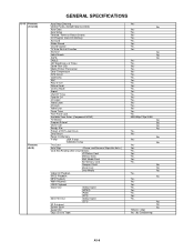
GENERAL SPECIFICATIONS G-10 On Screen Menu Yes Display Menu Type Icon (TV/VCR) Picture Yes Mode Yes Brightness Yes Contrast Yes Color Yes Tint Yes Sharpness Yes CableClear Yes Color Temperature Yes Display Format Yes SVM Yes Reset Yes Audio Yes SAP Yes Bass Yes Treble Yes Balance Yes Stable Sound Yes Surround Yes HDMI Yes Reset Yes TV Setup Yes Language Yes Clock Set Yes Auto Clock Yes Standard Time Yes Daylight Saving Time Yes TV/CABLE Yes...
GENERAL SPECIFICATIONS G-10 On Screen Menu Yes Display Menu Type Icon (TV/VCR) Picture Yes Mode Yes Brightness Yes Contrast Yes Color Yes Tint Yes Sharpness Yes CableClear Yes Color Temperature Yes Display Format Yes SVM Yes Reset Yes Audio Yes SAP Yes Bass Yes Treble Yes Balance Yes Stable Sound Yes Surround Yes HDMI Yes Reset Yes TV Setup Yes Language Yes Clock Set Yes Auto Clock Yes Standard Time Yes Daylight Saving Time Yes TV/CABLE Yes...
Service Manual
Page 15
G-11 On Screen Display (DVD) G-12 G-13 OSD Language Clock,Timer and Timer Back-up GENERAL SPECIFICATIONS Menu (DVD) Menu Type Language Menu Subtitle Audio OSD Language(Set up Language) Video E.B.L. (Enhanced Black Level) TV Screen Size(4:3/16:9) OSD Display On/Off Picture Mode (Video/Film/Auto) JPEG Interval Audio DRC (Dynamic Range Control) Dialogue (On DRC[TV] / Off DRC[Std]) Surround System Disc/Card Slot Password Lock/ Un Lock Parental Select Files HDMI (480p/1080i/720p) Output Open Close No Disc/ No Card Reading Disc/ Reading Card Play Still/Pause Stop ...
G-11 On Screen Display (DVD) G-12 G-13 OSD Language Clock,Timer and Timer Back-up GENERAL SPECIFICATIONS Menu (DVD) Menu Type Language Menu Subtitle Audio OSD Language(Set up Language) Video E.B.L. (Enhanced Black Level) TV Screen Size(4:3/16:9) OSD Display On/Off Picture Mode (Video/Film/Auto) JPEG Interval Audio DRC (Dynamic Range Control) Dialogue (On DRC[TV] / Off DRC[Std]) Surround System Disc/Card Slot Password Lock/ Un Lock Parental Select Files HDMI (480p/1080i/720p) Output Open Close No Disc/ No Card Reading Disc/ Reading Card Play Still/Pause Stop ...
Service Manual
Page 16
... Yes Yes Yes Yes Yes Yes Yes Yes Yes Yes Yes Yes Yes Yes Yes Yes Yes A3-5 G-14 Remote Control Unit GENERAL SPECIFICATIONS Unit Glow in Dark Remocon Remocon Format Format Custom Code Power Source Total Keys Keys Voltage(D.C) UM size x pcs TV/VCR DVD Power 1 2 3 4 5 6 7 8 9 0 ChannelChannel+ VolumeVolume+ Display Sleep Audio Select Mute Channel Return / SkipClosed Caption / Skip+ T-REC Rec/OTR Slow+ Play Stop Rew F.
... Yes Yes Yes Yes Yes Yes Yes Yes Yes Yes Yes Yes Yes Yes Yes Yes Yes A3-5 G-14 Remote Control Unit GENERAL SPECIFICATIONS Unit Glow in Dark Remocon Remocon Format Format Custom Code Power Source Total Keys Keys Voltage(D.C) UM size x pcs TV/VCR DVD Power 1 2 3 4 5 6 7 8 9 0 ChannelChannel+ VolumeVolume+ Display Sleep Audio Select Mute Channel Return / SkipClosed Caption / Skip+ T-REC Rec/OTR Slow+ Play Stop Rew F.
Service Manual
Page 17
... (TV/VCR) Features (DVD) GENERAL SPECIFICATIONS Auto Head Cleaning VIDEO PLUS+(SHOWVIEW,G-CODE) Auto Clock Auto Setup Forward / Reverse Picture Search CH Program (Auto CH Memory) Surround Stable Sound Closed Caption TV Auto Shut off Function End Call Index Search SQPB CABLE CM Skip(30sec x 6 Times) Comb Filter (3D) Mode (Picture Preference) Color Temperature SVM Circuit CableClear SAP Picture Size Picture Scroll Cinema Mode Aspect ON/OFF Timer Favorite CH CH Label Video Label CH Lock Video Lock Game Timer Front Panel Lock Available Scan Rates (Component/HDMI...
... (TV/VCR) Features (DVD) GENERAL SPECIFICATIONS Auto Head Cleaning VIDEO PLUS+(SHOWVIEW,G-CODE) Auto Clock Auto Setup Forward / Reverse Picture Search CH Program (Auto CH Memory) Surround Stable Sound Closed Caption TV Auto Shut off Function End Call Index Search SQPB CABLE CM Skip(30sec x 6 Times) Comb Filter (3D) Mode (Picture Preference) Color Temperature SVM Circuit CableClear SAP Picture Size Picture Scroll Cinema Mode Aspect ON/OFF Timer Favorite CH CH Label Video Label CH Lock Video Lock Game Timer Front Panel Lock Available Scan Rates (Component/HDMI...

Service Manual
Page 18
... Diagram Service Facility List Important Safeguard Sheet Information (Return) Netflix Card Switch Front Power (Tact) Channel Up Channel Down Volume Up Volume Down Play (VCR) Stop / Eject (VCR) F.FWD/Cue (VCR) Rew/Rev (VCR) REC/OTR (VCR) Play (DVD) Stop (DVD) Skip+ /Search+ (DVD) Skip- /Search- (DVD) Open/Close (DVD) Input Select Main Power SW Indicator Power REC/OTR T-REC TV/VCR DVD Terminals Front Video Input Audio Input S Input 4 in 1 Card Slot Rear Compact Flash Card Slot Other Terminal Video Input Audio Input S Input Video Output Audio Output Component...
... Diagram Service Facility List Important Safeguard Sheet Information (Return) Netflix Card Switch Front Power (Tact) Channel Up Channel Down Volume Up Volume Down Play (VCR) Stop / Eject (VCR) F.FWD/Cue (VCR) Rew/Rev (VCR) REC/OTR (VCR) Play (DVD) Stop (DVD) Skip+ /Search+ (DVD) Skip- /Search- (DVD) Open/Close (DVD) Input Select Main Power SW Indicator Power REC/OTR T-REC TV/VCR DVD Terminals Front Video Input Audio Input S Input 4 in 1 Card Slot Rear Compact Flash Card Slot Other Terminal Video Input Audio Input S Input Video Output Audio Output Component...
Service Manual
Page 37
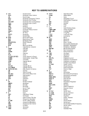
...Cassette : Capstan : Carrier : Channel : Clock : Clock (Syscon to Servo) : Combination, Comb Filter : Converter : Capstan Motor : Control : Cylinder : Cylinder-Motor : Cylinder-Sensor : Data (Syscon to Peak : Right : Recording : Recording-Chrominance : Recording-Luminance : Reel Brake : Reel Sensor : Reference : Regulated, Regulator : Rewind : Reverse : Radio Frequency : Remote Control : Relay : Serial Clock : Sensor Common : Serial Data : Segment : Select, Selector : Sensor : Search Mode : Serial Input : Sound Intermediate Frequency : Serial Output : Solenoid : Standard Play COM S. A A/C ACC...
...Cassette : Capstan : Carrier : Channel : Clock : Clock (Syscon to Servo) : Combination, Comb Filter : Converter : Capstan Motor : Control : Cylinder : Cylinder-Motor : Cylinder-Sensor : Data (Syscon to Peak : Right : Recording : Recording-Chrominance : Recording-Luminance : Reel Brake : Reel Sensor : Reference : Regulated, Regulator : Rewind : Reverse : Radio Frequency : Remote Control : Relay : Serial Clock : Sensor Common : Serial Data : Segment : Select, Selector : Sensor : Search Mode : Serial Input : Sound Intermediate Frequency : Serial Output : Solenoid : Standard Play COM S. A A/C ACC...
Service Manual
Page 39
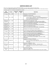
... the "ELECTRICAL ADJUSTMENT" (PG SHIFTER). 2 Adjust the PG SHIFTER manually. VCR mode VOL. (-) MIN 7 ALL mode VOL. (-) MIN 9 DVD mode (No disc) REC/OTR 4 2 Can be opened. 3 Refer to the "ELECTRICAL ADJUSTMENT" (On-Screen Display Adjustment). Initialization of factory on the screen when the Tray Lock is provided with the following SERVICE MODES so you set factory initialization, the memories are reset such as the clock setting, the channel setting, the POWER ON total hours, and PLAY/REC total...
... the "ELECTRICAL ADJUSTMENT" (PG SHIFTER). 2 Adjust the PG SHIFTER manually. VCR mode VOL. (-) MIN 7 ALL mode VOL. (-) MIN 9 DVD mode (No disc) REC/OTR 4 2 Can be opened. 3 Refer to the "ELECTRICAL ADJUSTMENT" (On-Screen Display Adjustment). Initialization of factory on the screen when the Tray Lock is provided with the following SERVICE MODES so you set factory initialization, the memories are reset such as the clock setting, the channel setting, the POWER ON total hours, and PLAY/REC total...

Service Manual
Page 53
... Disk Height Adjustment Reel Disk Height Adjustment X Value Adjustment Used to connect the test point of SERVICE and GROUND Confirmation of using a cassette tape, press the STOP/EJECT button to place the parts on the power and re-check the cable before checking the trouble points. Remove the TV/DVD/VCR Block from the set. Turn on... eject a cassette tape. D1-1 Alignment Tape ST-N5 ST-NF VTR cleaning kit SERVICING FIXTURES AND TOOLS Back tension cassette gauge Torque cassette gauge (KT-300NR) Taper nut driver 70909103 VTR lubrication kit 70909199 Grease 70909228 JG002B Adapter ...
... Disk Height Adjustment Reel Disk Height Adjustment X Value Adjustment Used to connect the test point of SERVICE and GROUND Confirmation of using a cassette tape, press the STOP/EJECT button to place the parts on the power and re-check the cable before checking the trouble points. Remove the TV/DVD/VCR Block from the set. Turn on... eject a cassette tape. D1-1 Alignment Tape ST-N5 ST-NF VTR cleaning kit SERVICING FIXTURES AND TOOLS Back tension cassette gauge Torque cassette gauge (KT-300NR) Taper nut driver 70909103 VTR lubrication kit 70909199 Grease 70909228 JG002B Adapter ...
Service Manual
Page 58
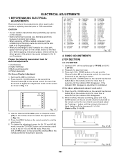
... the channel button (4) on the remote control for more than 2 seconds to end the adjustments. 5. button until the indicator REC disappears. ELECTRICAL ADJUSTMENTS 1. SIZE 05 V. Oscilloscope 2. If the indicator REC disappears, adjustment is blinking, press both VOL. BEFORE MAKING ELECTRICAL ADJUSTMENTS Read and perform these adjustments when repairing the circuits or replacing electrical parts or PCB assemblies. To display the adjustment screen for AV, CS and HD-MI mode...
... the channel button (4) on the remote control for more than 2 seconds to end the adjustments. 5. button until the indicator REC disappears. ELECTRICAL ADJUSTMENTS 1. SIZE 05 V. Oscilloscope 2. If the indicator REC disappears, adjustment is blinking, press both VOL. BEFORE MAKING ELECTRICAL ADJUSTMENTS Read and perform these adjustments when repairing the circuits or replacing electrical parts or PCB assemblies. To display the adjustment screen for AV, CS and HD-MI mode...
Service Manual
Page 62
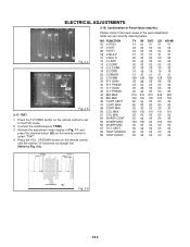
...ADJUSTMENTS 2-18: Confirmation of Fixed Value (step No.) Please check if the fixed values of Fig. 1-1 and press the channel button (53) on the remote control to select "TINT". 4. Connect the oscilloscope to set correctly referring below. FUNCTION... 57 TILT.CENT 58 TEST STEREO 59 TEST AUDIO TV AV DVD CS HD-MI 01 01 01 01 01... the TV/VIDEO button on the remote control until the section "A" becomes as straight line. (Refer to the DVD mode. 2. Activate the adjustment mode display of the each adjustment items are set to Fig. 2-6) NO. UP/DOWN button on the remote control to TP806....
...ADJUSTMENTS 2-18: Confirmation of Fixed Value (step No.) Please check if the fixed values of Fig. 1-1 and press the channel button (53) on the remote control to select "TINT". 4. Connect the oscilloscope to set correctly referring below. FUNCTION... 57 TILT.CENT 58 TEST STEREO 59 TEST AUDIO TV AV DVD CS HD-MI 01 01 01 01 01... the TV/VIDEO button on the remote control until the section "A" becomes as straight line. (Refer to the DVD mode. 2. Activate the adjustment mode display of the each adjustment items are set to Fig. 2-6) NO. UP/DOWN button on the remote control to TP806....
Service Manual
Page 94
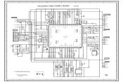
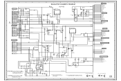
...3 2 1 G-15 NOTE: THIS SCHEMATIC DIAGRAM IS THE LATEST AT THE TIME OF PRINTING AND SUBJECT TO CHANGE WITHOUT NOTICE NOTE:THE DC VOLTAGE EACH PART WAS MEASURED WITH THE DIGITAL TESTER DURING PLAYBACK. A B R1014 100 1/4W R1021 100 1/4W 33K 4.7K C1030 C1032 0.0033 B SERVICE TP1001 NC R1026 22K C1046 6.3V 47... NC NC VSS X OUT 2.3 X IN 2.0 VCC 5.1 NC 0 NC 0 RESET 5.1 0 T-REC LED BOT A.ENV V.ENV NC NC NC NC CAP_FWD CAP_LIMIT D.V SYNC NC COLOR ROTARY HEAD AMP SW ENV COM IN VH SW AH SW LDM CTL CENTER LED IIC OFF VCR POWER ON-H SEG 1 SEG 2 SEG 3 SEG 4 5.1 A VCC 0 REC LED...
...3 2 1 G-15 NOTE: THIS SCHEMATIC DIAGRAM IS THE LATEST AT THE TIME OF PRINTING AND SUBJECT TO CHANGE WITHOUT NOTICE NOTE:THE DC VOLTAGE EACH PART WAS MEASURED WITH THE DIGITAL TESTER DURING PLAYBACK. A B R1014 100 1/4W R1021 100 1/4W 33K 4.7K C1030 C1032 0.0033 B SERVICE TP1001 NC R1026 22K C1046 6.3V 47... NC NC VSS X OUT 2.3 X IN 2.0 VCC 5.1 NC 0 NC 0 RESET 5.1 0 T-REC LED BOT A.ENV V.ENV NC NC NC NC CAP_FWD CAP_LIMIT D.V SYNC NC COLOR ROTARY HEAD AMP SW ENV COM IN VH SW AH SW LDM CTL CENTER LED IIC OFF VCR POWER ON-H SEG 1 SEG 2 SEG 3 SEG 4 5.1 A VCC 0 REC LED...
Service Manual
Page 95
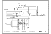
...NOTE: THIS SCHEMATIC DIAGRAM IS THE LATEST AT THE TIME OF PRINTING AND SUBJECT TO CHANGE WITHOUT NOTICE E F CAUTION: DIGITAL TRANSISTOR G H FROM/TO TV MICON GND DVD_RESET TV_POWER_H 8 DEGAUSS_H P.CON+3.3V_DEGI TV_POWER_FAIL AT+5.6V AT+3.3V TX RX DVD_H CHROMA_POWER_H FROM/TO TUNER/AV P.CON+...SOUND AMP/SURROUND P.CON+9V ZERO P.CON+5V GND FROM/TO CHROMA/PROGRESSIVE/PIN P.CON+9V P.CON+5V 4 GND FROM/TO Hi-Fi DVD_AUDIO_L DVD_AUDIO_R P.CON+5V_VCR P.CON+9V_VCR AT+5.6V GND 3 FROM/TO SYNC COUNT/CONNECTOR GND P.CON+5V MOTOR+12V P.CON+9V P.CON+3.3V_DEGI HDMI+4V 2 CAUTION: DIGITAL...
...NOTE: THIS SCHEMATIC DIAGRAM IS THE LATEST AT THE TIME OF PRINTING AND SUBJECT TO CHANGE WITHOUT NOTICE E F CAUTION: DIGITAL TRANSISTOR G H FROM/TO TV MICON GND DVD_RESET TV_POWER_H 8 DEGAUSS_H P.CON+3.3V_DEGI TV_POWER_FAIL AT+5.6V AT+3.3V TX RX DVD_H CHROMA_POWER_H FROM/TO TUNER/AV P.CON+...SOUND AMP/SURROUND P.CON+9V ZERO P.CON+5V GND FROM/TO CHROMA/PROGRESSIVE/PIN P.CON+9V P.CON+5V 4 GND FROM/TO Hi-Fi DVD_AUDIO_L DVD_AUDIO_R P.CON+5V_VCR P.CON+9V_VCR AT+5.6V GND 3 FROM/TO SYNC COUNT/CONNECTOR GND P.CON+5V MOTOR+12V P.CON+9V P.CON+3.3V_DEGI HDMI+4V 2 CAUTION: DIGITAL...
Service Manual
Page 97
...SOUND AMP/SURROUND SCHEMATIC DIAGRAM SOUND AMP IC IC351 AN7522N (VCR PCB) + - D NOTE: THIS SCHEMATIC DIAGRAM IS THE LATEST AT THE TIME OF PRINTING AND SUBJECT TO CHANGE WITHOUT NOTICE E F G H 8 7 21 20 6 SP351 MSF-2D5D10W CD352 SPEAKER CP303 CU14A102 A2502WR2-4P (L) SOUND L+ 4 4 5 SOUND L- 3 3 SOUND R- 2 2 SP352 MSF-2D5D10W SPEAKER SOUND R+ 1 1 (R) 4 3 2 CAUTION: DIGITAL... 15 16 NC BD VD L ONT AGC + SURR Tone Control Volume 2.2K Control MODE control VCC R IN Vref 32 31 30 29 2.5 7.8 4.6 ...PARTS MARKED BY ARE CRITICAL FOR SAFETY,USE ONES DESCRIBED IN PARTS LIST...
...SOUND AMP/SURROUND SCHEMATIC DIAGRAM SOUND AMP IC IC351 AN7522N (VCR PCB) + - D NOTE: THIS SCHEMATIC DIAGRAM IS THE LATEST AT THE TIME OF PRINTING AND SUBJECT TO CHANGE WITHOUT NOTICE E F G H 8 7 21 20 6 SP351 MSF-2D5D10W CD352 SPEAKER CP303 CU14A102 A2502WR2-4P (L) SOUND L+ 4 4 5 SOUND L- 3 3 SOUND R- 2 2 SP352 MSF-2D5D10W SPEAKER SOUND R+ 1 1 (R) 4 3 2 CAUTION: DIGITAL... 15 16 NC BD VD L ONT AGC + SURR Tone Control Volume 2.2K Control MODE control VCC R IN Vref 32 31 30 29 2.5 7.8 4.6 ...PARTS MARKED BY ARE CRITICAL FOR SAFETY,USE ONES DESCRIBED IN PARTS LIST...
Service Manual
Page 99
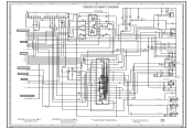
...PROGRESSIVE/PIN S801X S801Y GND R4202 3301/4W CAUTION:SINCE THESE PARTS MARKED BY ARE CRITICAL FOR SAFETY,USE ONES DESCRIBED IN PARTS LIST ONLY A B R001 100 R002 R004 100 47K W811 10 SCL AUDIO OUT 12 AFT 11 SDA R005 100K C D E F G H TUNER/AV SCHEMATIC DIAGRAM (VCR PCB) 14 SIF OUT VIDEO...1.5 2.2 3.5 R4228 C4241 68 0.1 B D AUDIO DRIVER Q4203 KTC3875S_Y_RTK B4201 W4BRH3.5X6X1.0X2 R4223 1.5K L4204...SCHEMATIC DIAGRAM IS THE LATEST AT THE TIME OF PRINTING AND SUBJECT TO CHANGE WITHOUT NOTICE D E NOTE:THE DC VOLTAGE EACH PART WAS MEASURED WITH THE DIGITAL TESTER DURING PLAYBACK...
...PROGRESSIVE/PIN S801X S801Y GND R4202 3301/4W CAUTION:SINCE THESE PARTS MARKED BY ARE CRITICAL FOR SAFETY,USE ONES DESCRIBED IN PARTS LIST ONLY A B R001 100 R002 R004 100 47K W811 10 SCL AUDIO OUT 12 AFT 11 SDA R005 100K C D E F G H TUNER/AV SCHEMATIC DIAGRAM (VCR PCB) 14 SIF OUT VIDEO...1.5 2.2 3.5 R4228 C4241 68 0.1 B D AUDIO DRIVER Q4203 KTC3875S_Y_RTK B4201 W4BRH3.5X6X1.0X2 R4223 1.5K L4204...SCHEMATIC DIAGRAM IS THE LATEST AT THE TIME OF PRINTING AND SUBJECT TO CHANGE WITHOUT NOTICE D E NOTE:THE DC VOLTAGE EACH PART WAS MEASURED WITH THE DIGITAL TESTER DURING PLAYBACK...
Service Manual
Page 101
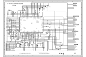
...SCL 6 SDA 7 SCL1 8 SDA1 9 BUS OFF(VCR) 10 VIDEO OUT 11 GND 12 AUDIO OUT L 13 AUDIO OUT R SCL_EEP SDA_EEP IIC_OFF SCL SDA SCL1 SDA1 BUS_OFF TEST_V_OUT AUDIO_OUT_L AUDIO_OUT_R NC 0 4 NC NC 0 5 NC C152 RESET SW Q106 10V 100 YK DTC114TKA SYSTEM RESET 3.45 IC103 PST3229NR 4.3 3.45 R174 3.2 3.2 1... SCL DVD_RESET CAUTION: DIGITAL TRANSISTOR 1 NOTE: THIS SCHEMATIC DIAGRAM IS THE LATEST AT THE TIME OF PRINTING AND SUBJECT TO CHANGE WITHOUT NOTICE NOTE:THE DC VOLTAGE AT EACH PART WAS MEASURED WITH THE DIGITAL TESTER WHEN THE COLOR BROADCAST WAS RECEIVED IN GOOD CONDITION AND...
...SCL 6 SDA 7 SCL1 8 SDA1 9 BUS OFF(VCR) 10 VIDEO OUT 11 GND 12 AUDIO OUT L 13 AUDIO OUT R SCL_EEP SDA_EEP IIC_OFF SCL SDA SCL1 SDA1 BUS_OFF TEST_V_OUT AUDIO_OUT_L AUDIO_OUT_R NC 0 4 NC NC 0 5 NC C152 RESET SW Q106 10V 100 YK DTC114TKA SYSTEM RESET 3.45 IC103 PST3229NR 4.3 3.45 R174 3.2 3.2 1... SCL DVD_RESET CAUTION: DIGITAL TRANSISTOR 1 NOTE: THIS SCHEMATIC DIAGRAM IS THE LATEST AT THE TIME OF PRINTING AND SUBJECT TO CHANGE WITHOUT NOTICE NOTE:THE DC VOLTAGE AT EACH PART WAS MEASURED WITH THE DIGITAL TESTER WHEN THE COLOR BROADCAST WAS RECEIVED IN GOOD CONDITION AND...


