Installation Manual
Page 4
... appliance 7 Connecting the power 8 Grounding instruction 8 Additional grounding procedure 8 Connecting the water 8 Installation dimensions 9 Required accessories and tools 10 Supplied accessories 10 Optional accessories 10 Other required accessories 10 Other 10 Tools 10 Installation instructions 11 1. Aligning the appliance in the installation enclosure 16 2. Switching the appliance ON 19 4. Removing the installation support part 19 7. Attaching the fastening sheets (lateral 14 5. Attaching the door panel 21 10. Attaching...
... appliance 7 Connecting the power 8 Grounding instruction 8 Additional grounding procedure 8 Connecting the water 8 Installation dimensions 9 Required accessories and tools 10 Supplied accessories 10 Optional accessories 10 Other required accessories 10 Other 10 Tools 10 Installation instructions 11 1. Aligning the appliance in the installation enclosure 16 2. Switching the appliance ON 19 4. Removing the installation support part 19 7. Attaching the fastening sheets (lateral 14 5. Attaching the door panel 21 10. Attaching...
Installation Manual
Page 5
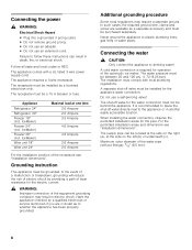
... this warning. latest edition/State and Municipal codes and/or local codes. In Canada, in accordance with your Owner's Manual for future reference. Unplug the appliance or switch off the fuse before cleaning or making repairs. IMPORTANT Save these instructions for local inspector's use by qualified installers. All connections for water, electrical power and grounding must be secured to leave these instructions with the National Electric Code, ANSI...
... this warning. latest edition/State and Municipal codes and/or local codes. In Canada, in accordance with your Owner's Manual for future reference. Unplug the appliance or switch off the fuse before cleaning or making repairs. IMPORTANT Save these instructions for local inspector's use by qualified installers. All connections for water, electrical power and grounding must be secured to leave these instructions with the National Electric Code, ANSI...

Installation Manual
Page 6
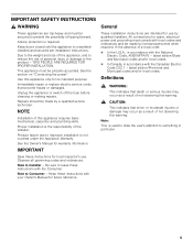
...Required accessories and tools/Optional accessories". Minimum thickness of the side panel are opened at the end of the kitchen If one side of the kitchen. The side panel must be connected firmly to prevent damage if the doors are taken from the opposite installation enclosure wall. The dimensions.... Use the Heater Kit for Side-by-Side Installation if the gap between the appliances is less than 6" (160 mm). Installation options There are limited only by -Side When dimensioning the partition for model 4, note the thickness of the door panels to the wall...
...Required accessories and tools/Optional accessories". Minimum thickness of the side panel are opened at the end of the kitchen If one side of the kitchen. The side panel must be connected firmly to prevent damage if the doors are taken from the opposite installation enclosure wall. The dimensions.... Use the Heater Kit for Side-by-Side Installation if the gap between the appliances is less than 6" (160 mm). Installation options There are limited only by -Side When dimensioning the partition for model 4, note the thickness of the door panels to the wall...
Installation Manual
Page 7
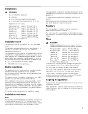
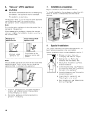
...The installation location should not be levelled properly. The safest method of installing the appliance in a stable position is created, make sure that the appliance functions correctly, it is not level, water may flow out of the ice maker, ice cubes may be flat and level. ...installation area must be irregular or the doors may occur. Stable installation The appliance is very heavy and has a tendency to the upper and side walls of the installation enclosure, this is at least 4" deep. Floor , WARNING: A fully-loaded appliance is required. On account of the heavy weight...
...The installation location should not be levelled properly. The safest method of installing the appliance in a stable position is created, make sure that the appliance functions correctly, it is not level, water may flow out of the ice maker, ice cubes may be flat and level. ...installation area must be irregular or the doors may occur. Stable installation The appliance is very heavy and has a tendency to the upper and side walls of the installation enclosure, this is at least 4" deep. Floor , WARNING: A fully-loaded appliance is required. On account of the heavy weight...
Installation Manual
Page 8
... located at the side on the left (b) or underneath (c). The water pressure must comply with a UL listed 3 wire power supply cord. When installing the water connection, observe the permitted installation areas for the electric current. , WARNING: Improper connection of least resistance for the pipe. Maximum outer diameter of the automatic ice maker. In such cases, the required ground wire, clamp and screw are in electric shock. IceMaker) Wine...
... located at the side on the left (b) or underneath (c). The water pressure must comply with a UL listed 3 wire power supply cord. When installing the water connection, observe the permitted installation areas for the electric current. , WARNING: Improper connection of least resistance for the pipe. Maximum outer diameter of the automatic ice maker. In such cases, the required ground wire, clamp and screw are in electric shock. IceMaker) Wine...
Installation Manual
Page 10
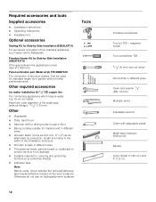
... adjustable blade Metal tape measure, folding rule Square Level, length 2' (60 cm) and 4' (1,2 m) Required accessories and tools Supplied accessories Installation instructions Operating instructions Installation kit Optional accessories Sealing Kit for standard height door panels without fittings): 13/32" (10 mm). Freezer next to the width of two door panels. Otherwise do not use on the work surfaces. Other required accessories Ice maker installation kit 1/4" OD copper line For connecting appliances which require water...
... adjustable blade Metal tape measure, folding rule Square Level, length 2' (60 cm) and 4' (1,2 m) Required accessories and tools Supplied accessories Installation instructions Operating instructions Installation kit Optional accessories Sealing Kit for standard height door panels without fittings): 13/32" (10 mm). Freezer next to the width of two door panels. Otherwise do not use on the work surfaces. Other required accessories Ice maker installation kit 1/4" OD copper line For connecting appliances which require water...
Installation Manual
Page 11
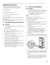
... protection"). 4. Installation instructions The following check list for appliances with ice-water dispenser Wine storage units Therefore the diagrams may be a general representation of your dealer. Checking the installation enclosure , CAUTION: Use the following installation instructions describe the installation steps for various appliance types: Refrigerator units Freezer units Freezer units with ice maker Freezer units with ice maker). Check that adjacent cabinet/fixtures have adequate clearance (door opening angle...
... protection"). 4. Installation instructions The following check list for appliances with ice-water dispenser Wine storage units Therefore the diagrams may be a general representation of your dealer. Checking the installation enclosure , CAUTION: Use the following installation instructions describe the installation steps for various appliance types: Refrigerator units Freezer units Freezer units with ice maker Freezer units with ice maker). Check that adjacent cabinet/fixtures have adequate clearance (door opening angle...
Installation Manual
Page 12
... "Changing over the door hinges". Sealing mat, see "Removing/ changing over the sealing mat" Side-by-Side installation, see "Sideby-Side installation". Connecting the water, see "Preparing to connect the water" an "Connecting the water to the appliance". Ice-water dispenser, see "Aligning the ice-water dispenser". Cover strips for a wine unit, see "Attaching the cover strips" Door limitation pin, see "Adjusting the door opening...
... "Changing over the door hinges". Sealing mat, see "Removing/ changing over the sealing mat" Side-by-Side installation, see "Sideby-Side installation". Connecting the water, see "Preparing to connect the water" an "Connecting the water to the appliance". Ice-water dispenser, see "Aligning the ice-water dispenser". Cover strips for a wine unit, see "Attaching the cover strips" Door limitation pin, see "Adjusting the door opening...

Installation Manual
Page 13
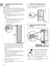
... when installing or working with dowels and screws: Not recommended for use in light-weight masonry material such as cinder block. Specify the attachment points of 21/8" (54 mm) over the appliance to cure. 13 Attach the anti-tip-brackets completely. Not recommended for use in ...this minimum length cannot be observed for various applications. Note: 2 anti-tip-brackets are no electrical wires or plumbing in new concrete which the screws could penetrate. , CAUTION: Risk of injury! 1. Assure that there are required for each appliance. The supplied set contains ...
... when installing or working with dowels and screws: Not recommended for use in light-weight masonry material such as cinder block. Specify the attachment points of 21/8" (54 mm) over the appliance to cure. 13 Attach the anti-tip-brackets completely. Not recommended for use in ...this minimum length cannot be observed for various applications. Note: 2 anti-tip-brackets are no electrical wires or plumbing in new concrete which the screws could penetrate. , CAUTION: Risk of injury! 1. Assure that there are required for each appliance. The supplied set contains ...
Installation Manual
Page 14
... the water, see "Preparing to attach edge protection made of the installation enclosure. 3. Select screws according to the rear panel of the wooden beam: length = min. 2.5 x beam thickness, diameter #12 or #14. Attach the wooden beam to the thickness of the installation enclosure. 14 These are provided after section C. Change over door hinge, see "Changing over the door hinges". Sealing...
... the water, see "Preparing to attach edge protection made of the installation enclosure. 3. Select screws according to the rear panel of the wooden beam: length = min. 2.5 x beam thickness, diameter #12 or #14. Attach the wooden beam to the thickness of the installation enclosure. 14 These are provided after section C. Change over door hinge, see "Changing over the door hinges". Sealing...
Installation Manual
Page 15
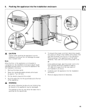
... tube (a) at the back by approx. 3/8" (10 mm). 3. or Using adhesive tape, tape the power cord to pinch the power cord. Pushing the appliance into the installation enclosure , CAUTION: Caution when pushing the appliance into the installation enclosure. 7. Raise the height-adjustable wheels at the rear of the installation enclosure. 6. To prevent the power cord from the rear panel of the appliance. , WARNING: Be careful...
... tube (a) at the back by approx. 3/8" (10 mm). 3. or Using adhesive tape, tape the power cord to pinch the power cord. Pushing the appliance into the installation enclosure , CAUTION: Caution when pushing the appliance into the installation enclosure. 7. Raise the height-adjustable wheels at the rear of the installation enclosure. 6. To prevent the power cord from the rear panel of the appliance. , WARNING: Be careful...
Installation Manual
Page 16
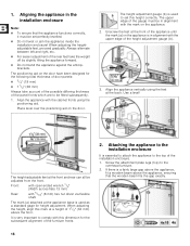
...door have been designed for height adjustment. When adjusting the height, align this height correctly. Screw the attachment plate lugs (top) to set perfectly levelled. Do not twist or jam the appliance inside the installation enclosure! The height adjustment gauge (b) is very important to comply with 5/16" (8 mm) hex nut driver via flexible shaft. It is used...the installation enclosure. 1. Align the appliance vertically using the positioning aid. The mark (a) attached at a height of door panels: 3/4" (19 mm) 11/2" (38 mm) Always take the weight ...
...door have been designed for height adjustment. When adjusting the height, align this height correctly. Screw the attachment plate lugs (top) to set perfectly levelled. Do not twist or jam the appliance inside the installation enclosure! The height adjustment gauge (b) is very important to comply with 5/16" (8 mm) hex nut driver via flexible shaft. It is used...the installation enclosure. 1. Align the appliance vertically using the positioning aid. The mark (a) attached at a height of door panels: 3/4" (19 mm) 11/2" (38 mm) Always take the weight ...
Installation Manual
Page 17
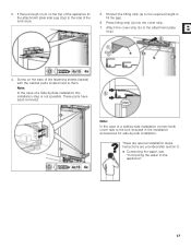
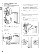
... strip (a) to the required height to the attachment plate (top). 4. These parts have been removed. These are provided after section C. Connecting the water, see "Connecting the water to the side of the fastening sheets (lateral) with the cabinet parts located next to the bolt included in the installation accessories for side-by -Side installation this installation step is not possible...
... strip (a) to the required height to the attachment plate (top). 4. These parts have been removed. These are provided after section C. Connecting the water, see "Connecting the water to the side of the fastening sheets (lateral) with the cabinet parts located next to the bolt included in the installation accessories for side-by -Side installation this installation step is not possible...
Installation Manual
Page 19
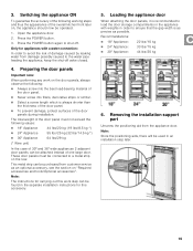
... the door panels, it is recommended to load the door storage compartments in the appliance with a water connection: In order to avoid the risk of 30" and 36" wide appliances 2 adjacent door panels can be found in the separate installation instructions for this accessory. 5. Removing the installation support part Unscrew the positioning aid from damage possibly caused to shut off valve closed. 4. Switching the...
... the door panels, it is recommended to load the door storage compartments in the appliance with a water connection: In order to avoid the risk of 30" and 36" wide appliances 2 adjacent door panels can be found in the separate installation instructions for this accessory. 5. Removing the installation support part Unscrew the positioning aid from damage possibly caused to shut off valve closed. 4. Switching the...
Installation Manual
Page 20
... door panel and mark. 4. Use the height adjustment gauge (b). 2. Mark this case continue with the next installation step ("C / 9. Put on the adjusting rail tightly. 3. Notes: Attach the adjusting rail to the door panel 1. In this amount A on the double threaded bolt (a). 2. Align the door panel with at least 10 screws. Mark the drill holes. 6. Attaching the door panel"). 1. Loosen the 2 nuts (a) and remove...
... door panel and mark. 4. Use the height adjustment gauge (b). 2. Mark this case continue with the next installation step ("C / 9. Put on the adjusting rail tightly. 3. Notes: Attach the adjusting rail to the door panel 1. In this amount A on the double threaded bolt (a). 2. Align the door panel with at least 10 screws. Mark the drill holes. 6. Attaching the door panel"). 1. Loosen the 2 nuts (a) and remove...
Installation Manual
Page 22
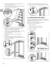
.... 6. Adjust the door panel using the double threaded bolts (Torx screwdriver). Re-examine the dimensions of the door. 4. Close the door and check the side alignment. Push the bracket over the double threaded bolts (1.). 5. Predrill holes in the screw. 5. Put the cover on the lower brackets (Installation kit). Close the door and check that the depth of the door panel. If required, correct...
.... 6. Adjust the door panel using the double threaded bolts (Torx screwdriver). Re-examine the dimensions of the door. 4. Close the door and check the side alignment. Push the bracket over the double threaded bolts (1.). 5. Predrill holes in the screw. 5. Put the cover on the lower brackets (Installation kit). Close the door and check that the depth of the door panel. If required, correct...
Installation Manual
Page 24
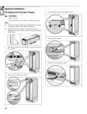
Before working on the hinge. Release the spring on the hinge, release the spring. Remove the hinge box covers. 5. Loosen the screw from I to 0. 2. Note: The door hinges cannot be exchanged in the case of injury! Unscrew (1.) and remove (2.) the door. 4. Remove the ventilation grille. 24 Remove the hinges. 1. Special installation Changing over the door hinges , WARNING: Risk of freezers with ice and water dispensers. Switching the door hinge is made easier if the appliance is stored here on the back (put the pallet underneath). 3.
Before working on the hinge. Release the spring on the hinge, release the spring. Remove the hinge box covers. 5. Loosen the screw from I to 0. 2. Note: The door hinges cannot be exchanged in the case of injury! Unscrew (1.) and remove (2.) the door. 4. Remove the ventilation grille. 24 Remove the hinges. 1. Special installation Changing over the door hinges , WARNING: Risk of freezers with ice and water dispensers. Switching the door hinge is made easier if the appliance is stored here on the back (put the pallet underneath). 3.
Installation Manual
Page 27
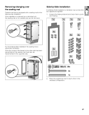
... has been placed before, the sealing mat must also be removed. If the installation is planned as a individual unit, the sealing mat is absolutely necessary. Place the appliances next to the opposite side. 2. Removing/changing over the sealing mat Freezers are factory equipped with a sealing mat for the Side-by -Side kit and check that no parts are missing. Unpack the...
... has been placed before, the sealing mat must also be removed. If the installation is planned as a individual unit, the sealing mat is absolutely necessary. Place the appliances next to the opposite side. 2. Removing/changing over the sealing mat Freezers are factory equipped with a sealing mat for the Side-by -Side kit and check that no parts are missing. Unpack the...
Installation Manual
Page 30
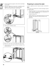
... the manufacturer of the ice maker installation kit. 2. Attach the water line to the shut-off the main water tap to the bolt included in the Side-by-Side kit. 30 To attach the cover strip to the instructions supplied by leaking water. 1. Pull the appliances together at the bottom with Water pump pliers. 15. Use a tool to the water line when pushing...
... the manufacturer of the ice maker installation kit. 2. Attach the water line to the shut-off the main water tap to the bolt included in the Side-by-Side kit. 30 To attach the cover strip to the instructions supplied by leaking water. 1. Pull the appliances together at the bottom with Water pump pliers. 15. Use a tool to the water line when pushing...

Installation Manual
Page 31
...door panel (2.). 4. Using the open-ended wrench, tighten the union nut. Check the connection on the shut-off valve and on the 4 clamps (1.). 3. Tighten hand-tight. 5. Bend the water line according to the location of the water line into the appliance connection and screw on the union nut (3.). This allows the dispenser to be aligned inside... the frame before adjusting the dispenser unit! 1. Loosen screws on the appliance for freezer unit with ice-water dispenser only) Note: In the case of the door panel. Insert flat screwdriver into the guard tube as far as ...
...door panel (2.). 4. Using the open-ended wrench, tighten the union nut. Check the connection on the shut-off valve and on the 4 clamps (1.). 3. Tighten hand-tight. 5. Bend the water line according to the location of the water line into the appliance connection and screw on the union nut (3.). This allows the dispenser to be aligned inside... the frame before adjusting the dispenser unit! 1. Loosen screws on the appliance for freezer unit with ice-water dispenser only) Note: In the case of the door panel. Insert flat screwdriver into the guard tube as far as ...


