Installation Manual
Page 4
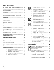
... installation 12 1. Attaching an alternative anti-tip-device 14 3. Aligning the base panel 18 3. Attaching the fixation strips to the appliance ..... 31 Aligning the ice-water dispenser 31 Attaching the cover strips 32 Adjusting the door opening angle 33 4 Adjusting the door.../changing over the sealing mat 27 Side-by -Side 6 Individual appliances with partition 6 Individual appliance at the end of the appliance 12 4. Table of Contents IMPORTANT SAFETY INSTRUCTIONS 5 Installation options 6 Individual appliance 6 Side-by -Side installation 27 Preparing to connect the water ...
... installation 12 1. Attaching an alternative anti-tip-device 14 3. Aligning the base panel 18 3. Attaching the fixation strips to the appliance ..... 31 Aligning the ice-water dispenser 31 Attaching the cover strips 32 Adjusting the door opening angle 33 4 Adjusting the door.../changing over the sealing mat 27 Side-by -Side 6 Individual appliances with partition 6 Individual appliance at the end of the appliance 12 4. Table of Contents IMPORTANT SAFETY INSTRUCTIONS 5 Installation options 6 Individual appliance 6 Side-by -Side installation 27 Preparing to connect the water ...
Installation Manual
Page 5
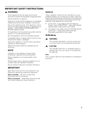
...in accordance with local codes and ordinances and be made by a qualified service technician. Anti-tip protection is not covered under the Appliance Warranty. Use this warning. Repairs should be made by qualified installers. Product failure due to something in accordance with the Consumer....- Note: This is used to draw the user's attention to improper installation is required. IMPORTANT SAFETY INSTRUCTIONS , WARNING These appliances are intended for local inspector's use by licensed personnel when required. Immediately repair or replace electric service cords that minor or ...
...in accordance with local codes and ordinances and be made by a qualified service technician. Anti-tip protection is not covered under the Appliance Warranty. Use this warning. Repairs should be made by qualified installers. Product failure due to something in accordance with the Consumer....- Note: This is used to draw the user's attention to improper installation is required. IMPORTANT SAFETY INSTRUCTIONS , WARNING These appliances are intended for local inspector's use by licensed personnel when required. Immediately repair or replace electric service cords that minor or ...

Installation Manual
Page 6
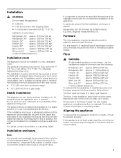
... "Kitchen Design Quick Reference". These are opened at the end of the kitchen If one side of the appliance is square and the proper size. 6 Individual appliance Individual appliances with partition Side-by-Side When dimensioning the partition for model 4, note the thickness of the...side panel must be connected firmly to prevent damage if the doors are limited only by -Side Installation if the gap between the appliances is placed in the installation enclosure. See the section on "Required accessories and tools/Optional accessories". Minimum thickness of ...
... "Kitchen Design Quick Reference". These are opened at the end of the kitchen If one side of the appliance is square and the proper size. 6 Individual appliance Individual appliances with partition Side-by-Side When dimensioning the partition for model 4, note the thickness of the...side panel must be connected firmly to prevent damage if the doors are limited only by -Side Installation if the gap between the appliances is placed in the installation enclosure. See the section on "Required accessories and tools/Optional accessories". Minimum thickness of ...
Installation Manual
Page 7
... correctly, it is always a firm connection between the installation enclosure and back wall! If the installation enclosure is adequately stable and the appliance can be flat and level. In particular ensure that all attachable furniture are less than 32 °F (0 °C). The floor must be installed ...rooms which are connected securely to direct sunlight and not placed near a heat source, such as the rest of the appliance. On account of the heavy weight of a fully loaded appliance, a load-bearing floor is not level, water may flow out of the niche be exposed to the floor or...
... correctly, it is always a firm connection between the installation enclosure and back wall! If the installation enclosure is adequately stable and the appliance can be flat and level. In particular ensure that all attachable furniture are less than 32 °F (0 °C). The floor must be installed ...rooms which are connected securely to direct sunlight and not placed near a heat source, such as the rest of the appliance. On account of the heavy weight of a fully loaded appliance, a load-bearing floor is not level, water may flow out of the niche be exposed to the floor or...
Installation Manual
Page 8
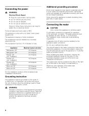
... Ampere 2.0 Ampere 2.0 Ampere For the installation position of the equipment grounding conductor may require a seperate ground. Grounding instruction This appliance must be behind the appliance. Connecting the power , WARNING: Electrical Shock Hazard Plug into a grounded 3 prong outlet. Do not ...local regulations may result in death, fire, or electrical shock. The supply pipe can result in electric shock. The appliance requires a 3-wire receptacle. When installing the water connection, observe the permitted installation areas for the water connection must ...
... Ampere 2.0 Ampere 2.0 Ampere For the installation position of the equipment grounding conductor may require a seperate ground. Grounding instruction This appliance must be behind the appliance. Connecting the power , WARNING: Electrical Shock Hazard Plug into a grounded 3 prong outlet. Do not ...local regulations may result in death, fire, or electrical shock. The supply pipe can result in electric shock. The appliance requires a 3-wire receptacle. When installing the water connection, observe the permitted installation areas for the water connection must ...
Installation Manual
Page 9
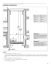
..." (381 mm) IMPORTANT ! IMPORTANT ! Legend: A Area for installation of the power connection C Opening depth of the enclosure must be accessed for service without uninstalling the appliance. If this is recommended the water-box be placed adjacent to be of the water connection It is not possible, place the recessed water box...
..." (381 mm) IMPORTANT ! IMPORTANT ! Legend: A Area for installation of the power connection C Opening depth of the enclosure must be accessed for service without uninstalling the appliance. If this is recommended the water-box be placed adjacent to be of the water connection It is not possible, place the recessed water box...
Installation Manual
Page 10
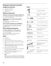
... work surfaces. Freedom Heater Kit for an ice maker. Other required accessories Ice maker installation kit 1/4" OD copper line For connecting appliances which require water, e.g. for Side-by -Side Installation BSEALKIT10 For permanent connection of two door panels. Other Stepladder &#... Operating instructions Installation kit Optional accessories Sealing Kit for Side-by -Side Installation XHEATKIT10 If the gap between the appliances is less than 6" (160 mm). Freezer next to protect the floor from damage Suitable material for covering and protecting ...
... work surfaces. Freedom Heater Kit for an ice maker. Other required accessories Ice maker installation kit 1/4" OD copper line For connecting appliances which require water, e.g. for Side-by -Side Installation BSEALKIT10 For permanent connection of two door panels. Other Stepladder &#... Operating instructions Installation kit Optional accessories Sealing Kit for Side-by -Side Installation XHEATKIT10 If the gap between the appliances is less than 6" (160 mm). Freezer next to protect the floor from damage Suitable material for covering and protecting ...
Installation Manual
Page 11
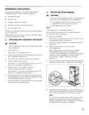
... may be used to attach the supplied accessories to the wall. 7. Remove accessories from inside the appliance until the installation is visibly damaged. appliance is made to the installation enclosure walls (see "Installation dimensions". 3. and remove accessories and installation ...Note: Do not remove transportation safety devices which was used subsequently for attaching an edge protection to special installation steps for various appliance types: Refrigerator units Freezer units Freezer units with ice maker Freezer units with ice ...
... may be used to attach the supplied accessories to the wall. 7. Remove accessories from inside the appliance until the installation is visibly damaged. appliance is made to the installation enclosure walls (see "Installation dimensions". 3. and remove accessories and installation ...Note: Do not remove transportation safety devices which was used subsequently for attaching an edge protection to special installation steps for various appliance types: Refrigerator units Freezer units Freezer units with ice maker Freezer units with ice ...
Installation Manual
Page 12
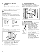
...-Side installation, see "Sideby-Side installation". Connecting the water, see "Preparing to connect the water" an "Connecting the water to the appliance". Ice-water dispenser, see "Aligning the ice-water dispenser". Cover strips for a wine unit, see "Attaching the cover strips..." Door limitation pin, see "Adjusting the door opening angle". 1. The appliance is 83 1/8" (2126 mm) tall. Transport of transportation (trolley, lifting truck or hand). 2. Note: Do not raise up from tipping. 12...
...-Side installation, see "Sideby-Side installation". Connecting the water, see "Preparing to connect the water" an "Connecting the water to the appliance". Ice-water dispenser, see "Aligning the ice-water dispenser". Cover strips for a wine unit, see "Attaching the cover strips..." Door limitation pin, see "Adjusting the door opening angle". 1. The appliance is 83 1/8" (2126 mm) tall. Transport of transportation (trolley, lifting truck or hand). 2. Note: Do not raise up from tipping. 12...

Installation Manual
Page 13
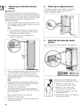
...to the section on "Installation dimensions". 2. Select the fastening screws according to secure the appliance. The anti-tip-brackets (a) must overlap a minimum of 21/8" (54 mm) over the appliance to the local conditions. Attach the anti-tip-brackets completely. The length of the ...of injury! Not recommended for use in light-weight masonry material such as cinder block. Assure that there are required for each appliance. The supplied set contains fastening screws for fastening with dowels. a sufficiently dimensioned wood board. Always wear safety glasses and...
...to the section on "Installation dimensions". 2. Select the fastening screws according to secure the appliance. The anti-tip-brackets (a) must overlap a minimum of 21/8" (54 mm) over the appliance to the local conditions. Attach the anti-tip-brackets completely. The length of the ...of injury! Not recommended for use in light-weight masonry material such as cinder block. Assure that there are required for each appliance. The supplied set contains fastening screws for fastening with dowels. a sufficiently dimensioned wood board. Always wear safety glasses and...
Installation Manual
Page 14
... enclosure width, thereby ensuring that there is equal to the width of the installation enclosure and accordingly transfer their location to the appliance. 2. Depending to the subsurface: Locate wall studs in the rear of the installation enclosure! Select screws according to the required length... at least 2" (50.8 mm). 3. Predrill the wooden beam. 6. Attach the wooden beam to connect the water". Length is no play between the appliance and the anti-tip-device. However, ensure that the beam can be attached securely. 4. Saw the wooden beam (cross section min. 3" x 4") to...
... enclosure width, thereby ensuring that there is equal to the width of the installation enclosure and accordingly transfer their location to the appliance. 2. Depending to the subsurface: Locate wall studs in the rear of the installation enclosure! Select screws according to the required length... at least 2" (50.8 mm). 3. Predrill the wooden beam. 6. Attach the wooden beam to connect the water". Length is no play between the appliance and the anti-tip-device. However, ensure that the beam can be attached securely. 4. Saw the wooden beam (cross section min. 3" x 4") to...
Installation Manual
Page 15
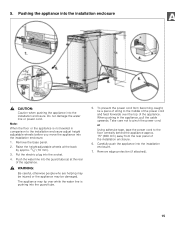
...tie a piece of string to the middle of the power cord and feed forwards over while the water line is not leveled in the appliance, pull the cable upwards. When pushing in comparison to pinch the power cord. Take care not to the installation enclosure adjust height adjustable ...installation enclosure. 7. Do not damage the water line or power cord. Raise the height-adjustable wheels at the rear of the appliance. Note: When the floor or the appliance is pushing into the installation enclosure. Push the water line into the socket. 4. Remove edge protection (if attached). 15 ...
...tie a piece of string to the middle of the power cord and feed forwards over while the water line is not leveled in the appliance, pull the cable upwards. When pushing in comparison to pinch the power cord. Take care not to the installation enclosure adjust height adjustable ...installation enclosure. 7. Do not damage the water line or power cord. Raise the height-adjustable wheels at the rear of the appliance. Note: When the floor or the appliance is pushing into the installation enclosure. Push the water line into the socket. 4. Remove edge protection (if attached). 15 ...
Installation Manual
Page 16
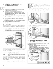
...) 11/2" (38 mm) Always take the weight off by slightly tilting the appliance forward. Do not bend the appliance against the anti-tipbrackets. The upper edge of the appliance until the mark (a) on the door have been designed for the following total thickness of ...dimension for height adjustment. Screw the attachment plate lugs (top) to set perfectly levelled. Do not twist or jam the appliance inside the installation enclosure! When adjusting the heightadjustable feet, proceed gradually: Always alternate between left and right, etc. For easier...
...) 11/2" (38 mm) Always take the weight off by slightly tilting the appliance forward. Do not bend the appliance against the anti-tipbrackets. The upper edge of the appliance until the mark (a) on the door have been designed for the following total thickness of ...dimension for height adjustment. Screw the attachment plate lugs (top) to set perfectly levelled. Do not twist or jam the appliance inside the installation enclosure! When adjusting the heightadjustable feet, proceed gradually: Always alternate between left and right, etc. For easier...
Installation Manual
Page 17
... the side of a Side-by -side installation. Instructions are special installation steps. If there enough room on the bars of the appliance fix the attachment plate side lugs (top) to the appliance". 17 3. Screw on the top of the fastening sheets (lateral) with the cabinet parts located next to the bolt included...
... the side of a Side-by -side installation. Instructions are special installation steps. If there enough room on the bars of the appliance fix the attachment plate side lugs (top) to the appliance". 17 3. Screw on the top of the fastening sheets (lateral) with the cabinet parts located next to the bolt included...
Installation Manual
Page 18
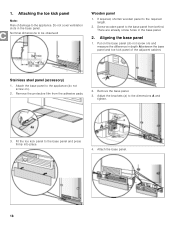
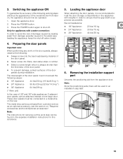
... panel. 2. Adjust the brackets (a) to the required length. 2. Nominal dimensions to the base panel and press firmly into place. 4. Attach the base panel to the appliance (do not screw on ). 2. Stainless steel panel (accessory) 1. Remove the base panel. 3. Put on the base panel (do not screw on ) and measure the difference.... 2. There are already screw holes in the base panel. Attaching the toe kick panel Note: Risk of the adjacent cabinet. Screw wooden panel to the appliance. Fit the toe kick panel to be observed: Wooden panel 1.
... panel. 2. Adjust the brackets (a) to the required length. 2. Nominal dimensions to the base panel and press firmly into place. 4. Attach the base panel to the appliance (do not screw on ). 2. Stainless steel panel (accessory) 1. Remove the base panel. 3. Put on the base panel (do not screw on ) and measure the difference.... 2. There are already screw holes in the base panel. Attaching the toe kick panel Note: Risk of the adjacent cabinet. Screw wooden panel to the appliance. Fit the toe kick panel to be observed: Wooden panel 1.
Installation Manual
Page 19
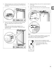
...always shorter than the thickness of the door panel. To prevent damage, protect surfaces of the overall kitchen front later on, the appliance should now be found in order to a metal strip on "Required accessories and tools/Optional accessories". Press the POWER button again to the... water pipe feeding the appliance, keep the shut-off . These door panels must not exceed the following working steps and thus the appearance of the door panels during ...
...always shorter than the thickness of the door panel. To prevent damage, protect surfaces of the overall kitchen front later on, the appliance should now be found in order to a metal strip on "Required accessories and tools/Optional accessories". Press the POWER button again to the... water pipe feeding the appliance, keep the shut-off . These door panels must not exceed the following working steps and thus the appearance of the door panels during ...
Installation Manual
Page 20
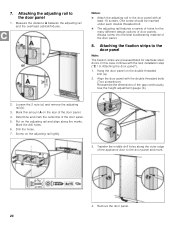
... 2 nuts (a) and remove the adjusting rail (b). 3. Put on the adjusting rail tightly. 3. Screw on the adjusting rail and align along the outer edge of the appliance door to the door panel Note: The fixation strips are pre-assembled for the many different design options of the door panel. 5.
... 2 nuts (a) and remove the adjusting rail (b). 3. Put on the adjusting rail tightly. 3. Screw on the adjusting rail and align along the outer edge of the appliance door to the door panel Note: The fixation strips are pre-assembled for the many different design options of the door panel. 5.
Installation Manual
Page 21
... vertical marks. 7. Using the positioning aid, mark the vertical sides of the door panel parallel. 9. Remove the fixing brackets (a) from behind! 1. 5. Open the appliance door. 21 Using a square, extend the drill hole marks which are screwed from the appliance door. Insert removed fixing brackets (a) into the adjusting rails (b) on the fixation strips. 2.
... vertical marks. 7. Using the positioning aid, mark the vertical sides of the door panel parallel. 9. Remove the fixing brackets (a) from behind! 1. 5. Open the appliance door. 21 Using a square, extend the drill hole marks which are screwed from the appliance door. Insert removed fixing brackets (a) into the adjusting rails (b) on the fixation strips. 2.
Installation Manual
Page 23
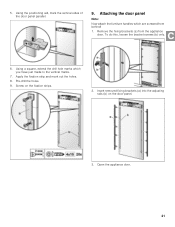
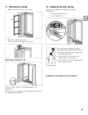
Attach the light switch cover. Side-by -side installation. 23 Insert the cover strip into the space between the appliances. Attach the cover strip (a) on the door. 12. The cover can be screwed to the door. Adjusting the door spring Rotate.... The cover rail is now complete. I = maximum spring tension 0 = no spring tension 2. 11. Instructions are special installation steps. Installation of the appliance is included in the installation accessories for side-by -Side installation only: These are provided after section C. Ice-water dispenser, see "Aligning the ...
Attach the light switch cover. Side-by -side installation. 23 Insert the cover strip into the space between the appliances. Attach the cover strip (a) on the door. 12. The cover can be screwed to the door. Adjusting the door spring Rotate.... The cover rail is now complete. I = maximum spring tension 0 = no spring tension 2. 11. Instructions are special installation steps. Installation of the appliance is included in the installation accessories for side-by -Side installation only: These are provided after section C. Ice-water dispenser, see "Aligning the ...
Installation Manual
Page 24
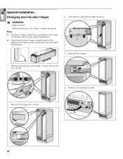
Unscrew (1.) and remove (2.) the door. 4. Remove the hinge box covers. 5. Loosen the screw from I to 0. 2. Remove the ventilation grille. 24 Before working on the back (put the pallet underneath). 3. Remove the hinges. 1. Note: The door hinges cannot be exchanged in the case of injury! Special installation Changing over the door hinges , WARNING: Risk of freezers with ice and water dispensers. Switching the door hinge is made easier if the appliance is stored here on the hinge, release the spring. Release the spring on the hinge.
Unscrew (1.) and remove (2.) the door. 4. Remove the hinge box covers. 5. Loosen the screw from I to 0. 2. Remove the ventilation grille. 24 Before working on the back (put the pallet underneath). 3. Remove the hinges. 1. Note: The door hinges cannot be exchanged in the case of injury! Special installation Changing over the door hinges , WARNING: Risk of freezers with ice and water dispensers. Switching the door hinge is made easier if the appliance is stored here on the hinge, release the spring. Release the spring on the hinge.