
VGC-RBxx Series Hard Disk Drive Replacement Instructions
Page 1
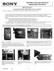
... difference does not affect the accuracy of your desktop computer.* ü Place your Sony Limited Warranty continue to avoid scratching the surface of these procedures. Disconnect the power cord. Remove jewelry before you through the replacement...VGC-RBxx Series Hard Disk Drive Replacement Instructions IMPORTANT! E 1/2 CAUTION! Step 3. PLEASE READ BEFORE YOU START These easy instructions are intended to guide you begin work to apply. 2 Screws [1] [2] Step 1. The terms of your desktop computer on both sides of the computer under these instructions. * Sony...
... difference does not affect the accuracy of your desktop computer.* ü Place your Sony Limited Warranty continue to avoid scratching the surface of these procedures. Disconnect the power cord. Remove jewelry before you through the replacement...VGC-RBxx Series Hard Disk Drive Replacement Instructions IMPORTANT! E 1/2 CAUTION! Step 3. PLEASE READ BEFORE YOU START These easy instructions are intended to guide you begin work to apply. 2 Screws [1] [2] Step 1. The terms of your desktop computer on both sides of the computer under these instructions. * Sony...
VGC-RBxx Series Hard Disk Drive Replacement Instructions
Page 2
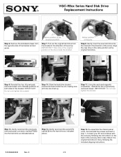
VGC-RBxx Series Hard Disk Drive Replacement Instructions Step 6. Notice position of the ...reconnect the serial ATA cable [2] into indicated positions on the back of the arrow. IMPORTANT! Gently reconnect the previously removed power connector marked P8 [1] into the bracket in the direction of the pins Step 8. Step 14. Connect your PC and continue...into the hard drive as indicated above . Re-assemble the chassis panel cover. Return the original hard drive to Sony following the instructions on both sides of the bracket and HDD Step 7. Notice position of the arrow. Step ...
VGC-RBxx Series Hard Disk Drive Replacement Instructions Step 6. Notice position of the ...reconnect the serial ATA cable [2] into indicated positions on the back of the arrow. IMPORTANT! Gently reconnect the previously removed power connector marked P8 [1] into the bracket in the direction of the pins Step 8. Step 14. Connect your PC and continue...into the hard drive as indicated above . Re-assemble the chassis panel cover. Return the original hard drive to Sony following the instructions on both sides of the bracket and HDD Step 7. Notice position of the arrow. Step ...
VGC-RBxx Series Optical Disk Drive Lower Replacement Instructions
Page 1
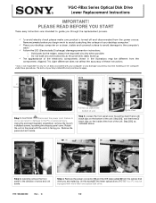
...to avoid damage to the PC or personal injury. Loosen the front panel cover by the edges, away from exposed circuitry when possible. VGC-RBxx Series Optical Disk Drive Lower Replacement Instructions IMPORTANT! The terms of the unit: Step [2B], as this example: the lower ...not affect the accuracy of the electronic components shown in the illustrations may be different from the power source. Pull two (2) clips at the bottom of your desktop computer.* ü Place your Sony Limited Wa rranty continue to guide you through the replacement process. ü To avoid electric...
...to avoid damage to the PC or personal injury. Loosen the front panel cover by the edges, away from exposed circuitry when possible. VGC-RBxx Series Optical Disk Drive Lower Replacement Instructions IMPORTANT! The terms of the unit: Step [2B], as this example: the lower ...not affect the accuracy of the electronic components shown in the illustrations may be different from the power source. Pull two (2) clips at the bottom of your desktop computer.* ü Place your Sony Limited Wa rranty continue to guide you through the replacement process. ü To avoid electric...
VGC-RBxx Series Optical Disk Drive Lower Replacement Instructions
Page 2
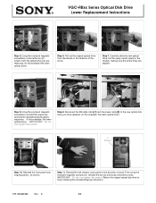
IMPORTANT! VGC-RBxx Series Optical Disk Drive Lower Replacement Instructions Step 5. Reconnect the IDE data cable [ 1] and the power cable [2] to the new optical disk drive you are aligned. 2 1 [1] [2] Step 8. Step 11. Pull out the original optical drive...: the lower optical drive.) Step 6. Return the original optical disk drive to its original position , as shown. Reinstall the front panel to Sony following the included shipping instructions P/N 994630200 Rev. C 2/2 Reinstall the left chassis cover panel in the direction of arrow.Then using the enclosed ...
IMPORTANT! VGC-RBxx Series Optical Disk Drive Lower Replacement Instructions Step 5. Reconnect the IDE data cable [ 1] and the power cable [2] to the new optical disk drive you are aligned. 2 1 [1] [2] Step 8. Step 11. Pull out the original optical drive...: the lower optical drive.) Step 6. Return the original optical disk drive to its original position , as shown. Reinstall the front panel to Sony following the included shipping instructions P/N 994630200 Rev. C 2/2 Reinstall the left chassis cover panel in the direction of arrow.Then using the enclosed ...
VGC-RBxx Series Optical Disk Drive Upper Replacement Instructions
Page 1
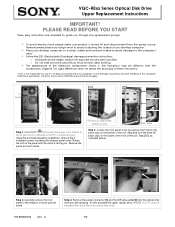
... equipped with your Sony Limited Wa rranty continue to do so can result in the illustrations may be different from the power source. Remove the power connector [1] and... Remove jewelry before you . VGC-RBxx Series Optical Disk Drive Upper Replacement Instructions IMPORTANT! PLEASE READ BEFORE YOU START These easy instructions are intended to the computer's case.* ü Follow... handling of the computer under these instructions. * Sony is facing you begin work to avoid scratching the surface of your desktop computer.* ü Place your desktop computer on a clean,...
... equipped with your Sony Limited Wa rranty continue to do so can result in the illustrations may be different from the power source. Remove the power connector [1] and... Remove jewelry before you . VGC-RBxx Series Optical Disk Drive Upper Replacement Instructions IMPORTANT! PLEASE READ BEFORE YOU START These easy instructions are intended to the computer's case.* ü Follow... handling of the computer under these instructions. * Sony is facing you begin work to avoid scratching the surface of your desktop computer.* ü Place your desktop computer on a clean,...
VGC-RBxx Series Optical Disk Drive Upper Replacement Instructions
Page 2
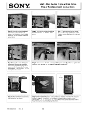
...Carefully slide the new optical drive into the newly vacant space in the direction of the arrow. Reinstall the front panel to Sony following the included shipping instructions P/N 994630100 Rev. Pull out the original optical drive from the optical drive you have replaced.... removed screwsfollowing the above sequence. ( In this example: the upper optical drive.) Step 6. VGC-RBxx Series Optical Disk Drive Upper Replacement Instructions Step 5. Reconnect the IDE data cable [ 1] and the power cable [2] to the new optical disk drive you are aligned. 2 1 [1] [2] Step ...
...Carefully slide the new optical drive into the newly vacant space in the direction of the arrow. Reinstall the front panel to Sony following the included shipping instructions P/N 994630100 Rev. Pull out the original optical drive from the optical drive you have replaced.... removed screwsfollowing the above sequence. ( In this example: the upper optical drive.) Step 6. VGC-RBxx Series Optical Disk Drive Upper Replacement Instructions Step 5. Reconnect the IDE data cable [ 1] and the power cable [2] to the new optical disk drive you are aligned. 2 1 [1] [2] Step ...
VAIO User Guide (Large File - 12.11 MB)
Page 8
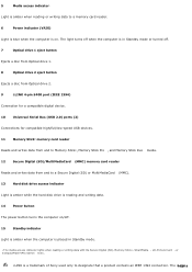
5 Media access indicator1 Light is amber when reading or writing data to a memory card reader. 6 Power indicator (VAIO) Light is blue when the computer is on /off . 7 Optical drive 1 eject button Ejects a disc from Optical drive 1. 8 Optical drive 2 eject button Ejects a disc from Optical drive... disk drive is a trademark of Sony used only to designate that a product contains an IEEE 1394 connection. The i.PLaIgNeK 8 i.LINK is reading and writing data. 14 Power button The power button turns the computer on . The light turns off when the computer is in Standby mode or turned...
5 Media access indicator1 Light is amber when reading or writing data to a memory card reader. 6 Power indicator (VAIO) Light is blue when the computer is on /off . 7 Optical drive 1 eject button Ejects a disc from Optical drive 1. 8 Optical drive 2 eject button Ejects a disc from Optical drive... disk drive is a trademark of Sony used only to designate that a product contains an IEEE 1394 connection. The i.PLaIgNeK 8 i.LINK is reading and writing data. 14 Power button The power button turns the computer on . The light turns off when the computer is in Standby mode or turned...
VAIO User Guide (Large File - 12.11 MB)
Page 10
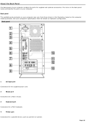
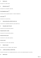
... on hardware configuration. Page 10 About the Back Panel The back panel of your computer contains the ports for a parallel device, such as a printer or scanner. See your computer. Back panel 1 AC Input port Connection for the supplied power cord. 2 Mouse port Connection for a PS/2® mouse. 3 Keyboard port Connection for a PS/2 keyboard...
... on hardware configuration. Page 10 About the Back Panel The back panel of your computer contains the ports for a parallel device, such as a printer or scanner. See your computer. Back panel 1 AC Input port Connection for the supplied power cord. 2 Mouse port Connection for a PS/2® mouse. 3 Keyboard port Connection for a PS/2 keyboard...
VAIO User Guide (Large File - 12.11 MB)
Page 11
... for an S-video cable (optional). 9 Modem line jack3 Connection for an RJ-11 telephone cable (optional). 10 i.LINK 6-pin S400 port (IEEE 1394) Connection and power for a microphone (optional). 5 Monitor port1 Connection for a VGA monitor. 6 Microphone jack Connection for a compatible digital device, such as...
... for an S-video cable (optional). 9 Modem line jack3 Connection for an RJ-11 telephone cable (optional). 10 i.LINK 6-pin S400 port (IEEE 1394) Connection and power for a microphone (optional). 5 Monitor port1 Connection for a VGA monitor. 6 Microphone jack Connection for a compatible digital device, such as...
VAIO User Guide (Large File - 12.11 MB)
Page 13
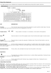
Volume Control Press a button to place the computer in certain software applications. Press the Mute button again to deactivate the...numeric keypad area to type numbers or to clicking the right mouse button. Page 13 About the Keyboard Your VAIO® keyboard uses a standard key arrangement with all software applications. Directional Arrows The Up, Down, Left, ... key with each function key may vary from one application to resume normal operation. Press the Power button or any key briefly, to the next. The task associated with the Microsoft® Windows® logo...
Volume Control Press a button to place the computer in certain software applications. Press the Mute button again to deactivate the...numeric keypad area to type numbers or to clicking the right mouse button. Page 13 About the Keyboard Your VAIO® keyboard uses a standard key arrangement with all software applications. Directional Arrows The Up, Down, Left, ... key with each function key may vary from one application to resume normal operation. Press the Power button or any key briefly, to the next. The task associated with the Microsoft® Windows® logo...
VAIO User Guide (Large File - 12.11 MB)
Page 16
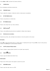
... OK to activate the channel selection.) 9 CLEAR button Use to backspace and delete entered text. 10 STANDBY button Press to place the computer in Stand by mode to reduce power consumption. 11 MY PICTURES button Press to view pictures or a slide show. 12 MY VIDEOS button Press to view videos from your...
... OK to activate the channel selection.) 9 CLEAR button Use to backspace and delete entered text. 10 STANDBY button Press to place the computer in Stand by mode to reduce power consumption. 11 MY PICTURES button Press to view pictures or a slide show. 12 MY VIDEOS button Press to view videos from your...
VAIO User Guide (Large File - 12.11 MB)
Page 18
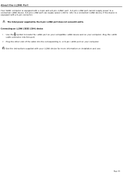
...device 1. Plug the i.LINK cable connector into the corresponding 4- See the instructions supplied with your i.LINK device for more information on your computer. A 6-pin i.LINK port can supply power (10V to 12V) to a connected i.LINK device, if the device is equipped with a 4-pin and a 6-pin i.LINK®... port. Page 18 Use the symbol to a connected i.LINK device. About the i.LINK Port Your VAIO® computer is equipped with a 6-pin connector. ...
...device 1. Plug the i.LINK cable connector into the corresponding 4- See the instructions supplied with your i.LINK device for more information on your computer. A 6-pin i.LINK port can supply power (10V to 12V) to a connected i.LINK device, if the device is equipped with a 4-pin and a 6-pin i.LINK®... port. Page 18 Use the symbol to a connected i.LINK device. About the i.LINK Port Your VAIO® computer is equipped with a 6-pin connector. ...

VAIO User Guide (Large File - 12.11 MB)
Page 19
See the online Specifications sheet for your computer's hardware configuration. Connecting a Display (Monitor) Connecting the Speakers Connecting the Keyboard and Mouse Connecting the Telephone and Modem Connecting the Power Cords Turning On Your Computer Page 19 Setting Up Your Computer Your computer may not be equipped with all of the hardware features described in the section.
See the online Specifications sheet for your computer's hardware configuration. Connecting a Display (Monitor) Connecting the Speakers Connecting the Keyboard and Mouse Connecting the Telephone and Modem Connecting the Power Cords Turning On Your Computer Page 19 Setting Up Your Computer Your computer may not be equipped with all of the hardware features described in the section.
VAIO User Guide (Large File - 12.11 MB)
Page 20
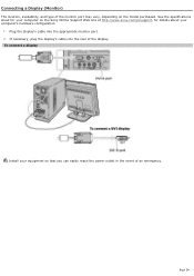
Plug the display's cable into the rear of the display. Page 20 To connect a display Install your equipment so that you can easily reach the power outlet in the event of an emergency. See the specifications sheet for details about your computer's hardware configuration 1. If necessary, plug the display's cable into the appropriate monitor port. 2. Connecting a Display (Monitor) The location, availability, and type of the monitor port may vary, depending on the Sony Online Support Web site at http://www.sony.com/pcsupport, for your computer on the model purchased.
Plug the display's cable into the rear of the display. Page 20 To connect a display Install your equipment so that you can easily reach the power outlet in the event of an emergency. See the specifications sheet for details about your computer's hardware configuration 1. If necessary, plug the display's cable into the appropriate monitor port. 2. Connecting a Display (Monitor) The location, availability, and type of the monitor port may vary, depending on the Sony Online Support Web site at http://www.sony.com/pcsupport, for your computer on the model purchased.
VAIO User Guide (Large File - 12.11 MB)
Page 21
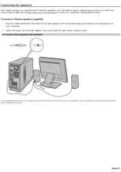
...illus tration s hown here. See your computer's specifications sheet. Page 21 Plug the cable attached to view your c omputer's online s pec ific ations s heet for more information about supplied accessories, go to the Sony online support Web site at http://www.sony.com/pcsupport to the back of the ...right speaker into the Headphones jack located on the back panel of the AC adapter into a grounded AC wall outlet or power strip. Connecting the Speakers Your VAIO® computer is supplied with...
...illus tration s hown here. See your computer's specifications sheet. Page 21 Plug the cable attached to view your c omputer's online s pec ific ations s heet for more information about supplied accessories, go to the Sony online support Web site at http://www.sony.com/pcsupport to the back of the ...right speaker into the Headphones jack located on the back panel of the AC adapter into a grounded AC wall outlet or power strip. Connecting the Speakers Your VAIO® computer is supplied with...

VAIO User Guide (Large File - 12.11 MB)
Page 24
Connecting the Power Cords 1. Plug both the display and computer power cords into the back of the computer. 2. To connect the power cords Page 24 Plug the power cord into a grounded AC wall outlet or a power strip.
Connecting the Power Cords 1. Plug both the display and computer power cords into the back of the computer. 2. To connect the power cords Page 24 Plug the power cord into a grounded AC wall outlet or a power strip.

VAIO User Guide (Large File - 12.11 MB)
Page 25
... connections required to use these features before you to turn on the power. 3. See the section, Setting Up Media Center. 1. Press the power button on the right speaker to restart your computer. Press the power button on the display to this prompt immediately. Respond to turn on... the power. Turning On Your Computer When you start your computer for the first time, your computer may detect new equipment and ...
... connections required to use these features before you to turn on the power. 3. See the section, Setting Up Media Center. 1. Press the power button on the right speaker to restart your computer. Press the power button on the display to this prompt immediately. Respond to turn on... the power. Turning On Your Computer When you start your computer for the first time, your computer may detect new equipment and ...
VAIO User Guide (Large File - 12.11 MB)
Page 38
...to shut down on the first attempt. About the Power button If your computer stops responding, press and hold the Power button for your computer to turn off automatically-the power indicator light turns off. 4. You may need to repeat this procedure if your computer does not shut down . Page 38 To avoid loss... of time. To turn off the computer. Turn off your computer for an extended period of data, do not use the Power button to turn off your computer 1. Turning Off Your Computer Follow these steps when you are ready to turn off any prompts about saving...
...to shut down on the first attempt. About the Power button If your computer stops responding, press and hold the Power button for your computer to turn off automatically-the power indicator light turns off. 4. You may need to repeat this procedure if your computer does not shut down . Page 38 To avoid loss... of time. To turn off the computer. Turn off your computer for an extended period of data, do not use the Power button to turn off your computer 1. Turning Off Your Computer Follow these steps when you are ready to turn off any prompts about saving...

VAIO User Guide (Large File - 12.11 MB)
Page 46
... described in this section. Failure to disconnect your computer may vary from its power source may be equipped with an unpainted metal portion of your computer from the illustrations, depending on the computer purchased. The interior hardware configuration of the chassis while...example, cellophane wrappers). Overview The upgrading procedures described in this section assume that you open the computer or connect your computer Disconnect the computer from its power source and from telecommunications links, networks, or modems before you plan to the integrated circuits. ...
... described in this section. Failure to disconnect your computer may vary from its power source may be equipped with an unpainted metal portion of your computer from the illustrations, depending on the computer purchased. The interior hardware configuration of the chassis while...example, cellophane wrappers). Overview The upgrading procedures described in this section assume that you open the computer or connect your computer Disconnect the computer from its power source and from telecommunications links, networks, or modems before you plan to the integrated circuits. ...
VAIO User Guide (Large File - 12.11 MB)
Page 50
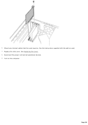
Attach any internal cables that the card requires. Reconnect the power cord and all peripheral devices. 9. See the instructions supplied with the add-on the computer. Turn on card. 7. Replace the side cover. See Replacing the cover. 8. Page 50 6.
Attach any internal cables that the card requires. Reconnect the power cord and all peripheral devices. 9. See the instructions supplied with the add-on the computer. Turn on card. 7. Replace the side cover. See Replacing the cover. 8. Page 50 6.

