Operating Instructions
Page 1
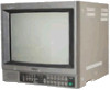
cam OOOO Deno ww, 000000 0 0 00000 This illustration shows PVM-1342Q/PVM-1341. Mode d'emploi Page 16 Avant la mise en service de cet appareil, priere de lire attentivement ce mode d'emploi que Ion conservera pour toute reference ulterieure. Cette illustration represente les modeles PVM-1342Q/PVM-1341. © 1988 by Sony Corporation SONY® TRINITRON® Color Video Monitor 3-786-761-27 (1) Operating Instructions Page 2 Before operating the unit, please read this manual thoroughly and retain it for future reference.
cam OOOO Deno ww, 000000 0 0 00000 This illustration shows PVM-1342Q/PVM-1341. Mode d'emploi Page 16 Avant la mise en service de cet appareil, priere de lire attentivement ce mode d'emploi que Ion conservera pour toute reference ulterieure. Cette illustration represente les modeles PVM-1342Q/PVM-1341. © 1988 by Sony Corporation SONY® TRINITRON® Color Video Monitor 3-786-761-27 (1) Operating Instructions Page 2 Before operating the unit, please read this manual thoroughly and retain it for future reference.
Operating Instructions
Page 5
... display, up to the corresponding IN connector is depressed, the monitor can be displayed with a single cable. Horizontal resolution is also available. Four color systems available (PVM-1344Q/PVM-1342Q only) The monitor can be input through this connector is in a composite video ...signal and assuring the video quality. Light-touch picture adjustment buttons (except PVM-1340) The aperture, brightness, chroma, phase, ...
... display, up to the corresponding IN connector is depressed, the monitor can be displayed with a single cable. Horizontal resolution is also available. Four color systems available (PVM-1344Q/PVM-1342Q only) The monitor can be input through this connector is in a composite video ...signal and assuring the video quality. Light-touch picture adjustment buttons (except PVM-1340) The aperture, brightness, chroma, phase, ...
Operating Instructions
Page 7
... set levels (memorized levels for a signal fed through the Y/C-INPUT connectors or VTR connector. for the NTSC signals. Press the switch again to be monitored. A: for a signal fed through the LINE A connectors. A: for a signal fed through the LINE A connectors. When both the Y/C-INPUT and... the DIGITAL RGB connector. Gain and BIAS controls are connected to make the contrast, color intensity and brightness stronger or - B: for PVM-1444OM). To release the memorized levels and restore the factory set levels, while pressing this button with a pencil or a similar object ...
... set levels (memorized levels for a signal fed through the Y/C-INPUT connectors or VTR connector. for the NTSC signals. Press the switch again to be monitored. A: for a signal fed through the LINE A connectors. A: for a signal fed through the LINE A connectors. When both the Y/C-INPUT and... the DIGITAL RGB connector. Gain and BIAS controls are connected to make the contrast, color intensity and brightness stronger or - B: for PVM-1444OM). To release the memorized levels and restore the factory set levels, while pressing this button with a pencil or a similar object ...
Operating Instructions
Page 8
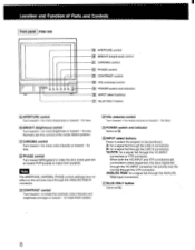
... fed through the ANALOG RGB input connectors. _ (211BLUE ONLY button Same as El. 261INPUT select buttons Press to select the program to be monitored. ANALOG RGB: for more sharpness or toward - ACHROMA control Turn toward + for a signal fed through the LINE A connectors. for more color... intensity or toward - Location and Function of Parts and Controls Front panel PVM-134O U U fi) 0 0 0 2 19 APERTURE control 20 BRIGHT (brightness) control 21 CHROMA control 0 PHASE control 231 CONTRAST control 1241 VOL ...
... fed through the ANALOG RGB input connectors. _ (211BLUE ONLY button Same as El. 261INPUT select buttons Press to select the program to be monitored. ANALOG RGB: for more sharpness or toward - ACHROMA control Turn toward + for a signal fed through the LINE A connectors. for more color... intensity or toward - Location and Function of Parts and Controls Front panel PVM-134O U U fi) 0 0 0 2 19 APERTURE control 20 BRIGHT (brightness) control 21 CHROMA control 0 PHASE control 231 CONTRAST control 1241 VOL ...
Operating Instructions
Page 9
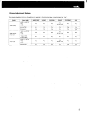
Picture Adjustment Buttons The picture adjustment buttons of each monitor operate in the following input mode (indicated as "Yes"). Model PVM-1344Q PVM-1342Q/ PVM-1341 PVM-1340 Input mode • LINE A, LINE B • Y/C • VTR Analog RGB Component • LINE A, LINE B • Y/C • VTR • Digital RGB • Analog RGB • ...
Picture Adjustment Buttons The picture adjustment buttons of each monitor operate in the following input mode (indicated as "Yes"). Model PVM-1344Q PVM-1342Q/ PVM-1341 PVM-1340 Input mode • LINE A, LINE B • Y/C • VTR Analog RGB Component • LINE A, LINE B • Y/C • VTR • Digital RGB • Analog RGB • ...
Operating Instructions
Page 13
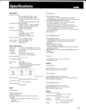
... mm (Typical) Peripheral area: 0.8 mm (Typical) Raster size stability H: 1.0%, V: 1.5% High voltage regulation Audio output 0.6 W (Max.) CRT PVM-1344Q/PVM-1342Q: SMPTE-C (American-standard-phosphor) PVM-1341/PVM-1340: P-22 Chromacity coordinates (SMPTE C only) X Y Red Green Blue 0.630 0.310 0.155 0.340 0.595 0.070 _ (tolerance ±...is fed to the G or Y channels, the monitor can be activated in the internal sync mode. 75 ohms terminated automatically with no cable connected to the output connector CTRL S: Minijack PVM-1342Q/PVM-1341 only EXT SYNC: BNC connector composite sync ...
... mm (Typical) Peripheral area: 0.8 mm (Typical) Raster size stability H: 1.0%, V: 1.5% High voltage regulation Audio output 0.6 W (Max.) CRT PVM-1344Q/PVM-1342Q: SMPTE-C (American-standard-phosphor) PVM-1341/PVM-1340: P-22 Chromacity coordinates (SMPTE C only) X Y Red Green Blue 0.630 0.310 0.155 0.340 0.595 0.070 _ (tolerance ±...is fed to the G or Y channels, the monitor can be activated in the internal sync mode. 75 ohms terminated automatically with no cable connected to the output connector CTRL S: Minijack PVM-1342Q/PVM-1341 only EXT SYNC: BNC connector composite sync ...


