Warranty Card
Page 2
has established a group to supply you with technical support: Sony Technical Support URL: www.sony.com/displays/support EMAIL: [email protected] or write to : Sony of Canada Ltd. has established a group to supply you with technical support: Sony Computer Products Support URL: www.sony.ca/sonyca/customersupport_contactus.shtml EMAIL: it_help@sony.ca or write to : Sony Electronics, Inc. 12451 Gateway Blvd. CIC 115...
has established a group to supply you with technical support: Sony Technical Support URL: www.sony.com/displays/support EMAIL: [email protected] or write to : Sony of Canada Ltd. has established a group to supply you with technical support: Sony Computer Products Support URL: www.sony.ca/sonyca/customersupport_contactus.shtml EMAIL: it_help@sony.ca or write to : Sony Electronics, Inc. 12451 Gateway Blvd. CIC 115...
Operating Instructions
Page 1
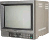
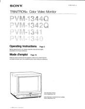
cam OOOO Deno ww, 000000 0 0 00000 This illustration shows PVM-1342Q/PVM-1341. Cette illustration represente les modeles PVM-1342Q/PVM-1341. © 1988 by Sony Corporation Mode d'emploi Page 16 Avant la mise en service de cet appareil, priere de lire attentivement ce mode d'emploi que Ion conservera pour toute reference ulterieure. SONY® TRINITRON® Color Video Monitor 3-786-761-27 (1) Operating Instructions Page 2 Before operating the unit, please read this manual thoroughly and retain it for future reference.
cam OOOO Deno ww, 000000 0 0 00000 This illustration shows PVM-1342Q/PVM-1341. Cette illustration represente les modeles PVM-1342Q/PVM-1341. © 1988 by Sony Corporation Mode d'emploi Page 16 Avant la mise en service de cet appareil, priere de lire attentivement ce mode d'emploi que Ion conservera pour toute reference ulterieure. SONY® TRINITRON® Color Video Monitor 3-786-761-27 (1) Operating Instructions Page 2 Before operating the unit, please read this manual thoroughly and retain it for future reference.
Operating Instructions
Page 2
... (servicing) instructions in the literature accompanying the appliance. CAUTION TO REDUCE THE RISK OF ELECTRIC SHOCK, DO NOT REMOVE COVER ;OR BACK). NO USER-SERVICEABLE PARTS INSIDE...uses, and can radiate radio frequency energy and if not installed and used in accordance with one of the complete system has a label with the instructions manual, may be required to correct the interference. Refer to rain or moisture. REFER SERVICING TO QUALIFIED SERVICE PERSONNEL. Record the model and serial numbers in the USA Warning - English Owner's Record The model and serial numbers...
... (servicing) instructions in the literature accompanying the appliance. CAUTION TO REDUCE THE RISK OF ELECTRIC SHOCK, DO NOT REMOVE COVER ;OR BACK). NO USER-SERVICEABLE PARTS INSIDE...uses, and can radiate radio frequency energy and if not installed and used in accordance with one of the complete system has a label with the instructions manual, may be required to correct the interference. Refer to rain or moisture. REFER SERVICING TO QUALIFIED SERVICE PERSONNEL. Record the model and serial numbers in the USA Warning - English Owner's Record The model and serial numbers...
Operating Instructions
Page 3
...power cord, pull it any questions about this unit, contact your authorized Sony dealer. 000000 O For the customers in Canada This apparatus complies with the Class A limits for radio noise emissions set out in which to prevent internal heat build-up. Never use...Location and function of parts and controls 6 Front panel 6 Rear panel 10 Specifications 13 This instruction manual covers the following models. If you have it checked by qualified personnel before cleaning it as thinner or benzine, or abrasive cleansers since these will damage the cabinet. PVM-1340 On safety ...
...power cord, pull it any questions about this unit, contact your authorized Sony dealer. 000000 O For the customers in Canada This apparatus complies with the Class A limits for radio noise emissions set out in which to prevent internal heat build-up. Never use...Location and function of parts and controls 6 Front panel 6 Rear panel 10 Specifications 13 This instruction manual covers the following models. If you have it checked by qualified personnel before cleaning it as thinner or benzine, or abrasive cleansers since these will damage the cabinet. PVM-1340 On safety ...
Operating Instructions
Page 4
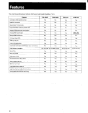
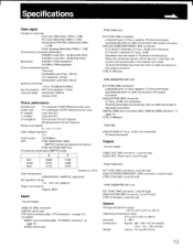
... SMPTE-C phosphor Black-tinted Trinitron tube Super Fine Pitch Trinitron picture tube Analog RGB/component input/output Analog RGB input/output Digital RGB input (9-pin) Y/C input (4-pin DIN) VTR input (8-pin) Control S input/output Automatic termination of BNC-type input connectors Color systems available Comb filter Blue only mode Underscan mode . Horizontal/vertical delay mode Users control memory • - External sync input Color temperature selector Light-touch picture adjustment buttons EIA standard 19-inch rack mounting PVM-1344O PVM-1342Q ^ Yes Yes...
... SMPTE-C phosphor Black-tinted Trinitron tube Super Fine Pitch Trinitron picture tube Analog RGB/component input/output Analog RGB input/output Digital RGB input (9-pin) Y/C input (4-pin DIN) VTR input (8-pin) Control S input/output Automatic termination of BNC-type input connectors Color systems available Comb filter Blue only mode Underscan mode . Horizontal/vertical delay mode Users control memory • - External sync input Color temperature selector Light-touch picture adjustment buttons EIA standard 19-inch rack mounting PVM-1344O PVM-1342Q ^ Yes Yes...
Operating Instructions
Page 5
... this connector with a single cable. Users control memory (PVM-1344Q only) The desired aperture, brightness, chroma and phase levels can be stored in the underscan mode are selected by touching the buttons lightly. External sync input (except PVM-1340) When the EXT SYNC (or ANALOG/DIGITAL (EXT SYNC)) button is connected to a VCR having the 8-pin TV connector, video and audio signals can be input through this connector. Color temperature selector Color temperature of the screen when the monitor...
... this connector with a single cable. Users control memory (PVM-1344Q only) The desired aperture, brightness, chroma and phase levels can be stored in the underscan mode are selected by touching the buttons lightly. External sync input (except PVM-1340) When the EXT SYNC (or ANALOG/DIGITAL (EXT SYNC)) button is connected to a VCR having the 8-pin TV connector, video and audio signals can be input through this connector. Color temperature selector Color temperature of the screen when the monitor...
Operating Instructions
Page 6
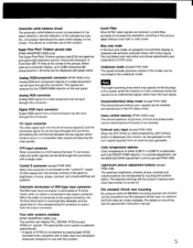
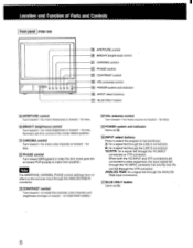
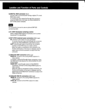
... Parts and Controls Front panel PVM-1344O rfilff:131E33938 a Front panel PVM-1342QIPVM-1341- r LEM 6 BIAS and GAIN adjustment controls J MEMORY button 13 1 RESET button and response indicator 41 APERTURE buttons BRIGHT (brightness) buttons 6 CHROMA buttons FT PHASE buttons CONTRAST buttons 11 VOL (volume) buttons 10 POWER switch and indicator 11 INPUT select buttons 12 EXT SYNC button 13 H-V DELAY button 1141 UNDER SCAN button 15 BLUE ONLY button 16 Color system indicators 1 BIAS and GAIN adjustment controls 13 1 RESET button and response indicator 141 APERTURE buttons 5 BRIGHT (brightness...
... Parts and Controls Front panel PVM-1344O rfilff:131E33938 a Front panel PVM-1342QIPVM-1341- r LEM 6 BIAS and GAIN adjustment controls J MEMORY button 13 1 RESET button and response indicator 41 APERTURE buttons BRIGHT (brightness) buttons 6 CHROMA buttons FT PHASE buttons CONTRAST buttons 11 VOL (volume) buttons 10 POWER switch and indicator 11 INPUT select buttons 12 EXT SYNC button 13 H-V DELAY button 1141 UNDER SCAN button 15 BLUE ONLY button 16 Color system indicators 1 BIAS and GAIN adjustment controls 13 1 RESET button and response indicator 141 APERTURE buttons 5 BRIGHT (brightness...
Operating Instructions
Page 7
... sync signal from the displayed composite video signal (INT). 7 To operate the monitor on an external sync signal fed through the EXT SYNC connector on the sync signal from the displayed composite video signal. For EXT SYNC selector Depress to the explanation of the color system being received lights up in the left quarter of analog RGB or digital RGB signals. 8 CONTRAST buttons Press + to turn the monitor off the red and green signals. 1 BIAS and GAIN adjustment controls Used for the R (red), G (green) and B (blue) screens...
... sync signal from the displayed composite video signal (INT). 7 To operate the monitor on an external sync signal fed through the EXT SYNC connector on the sync signal from the displayed composite video signal. For EXT SYNC selector Depress to the explanation of the color system being received lights up in the left quarter of analog RGB or digital RGB signals. 8 CONTRAST buttons Press + to turn the monitor off the red and green signals. 1 BIAS and GAIN adjustment controls Used for the R (red), G (green) and B (blue) screens...
Operating Instructions
Page 8
... control 231 CONTRAST control 1241 VOL (volume) control 1251 POWER switch and indicator a INPUT select buttons 27 BLUE ONLY button 1191APERTURE control Turn toward + for less. 1251POWER switch and indicator Same as M. ANALOG RGB: for more sharpness or toward - When both the Y/C-INPUT and VTR connectors are connected to video equipment, the input signal fed through the Y/C-INPUT connector has priority over the one fed through the ANALOG RGB IN connector. 231CONTRAST control Turn toward + to make the contrast, color intensity and brightness...
... control 231 CONTRAST control 1241 VOL (volume) control 1251 POWER switch and indicator a INPUT select buttons 27 BLUE ONLY button 1191APERTURE control Turn toward + for less. 1251POWER switch and indicator Same as M. ANALOG RGB: for more sharpness or toward - When both the Y/C-INPUT and VTR connectors are connected to video equipment, the input signal fed through the Y/C-INPUT connector has priority over the one fed through the ANALOG RGB IN connector. 231CONTRAST control Turn toward + to make the contrast, color intensity and brightness...
Operating Instructions
Page 9
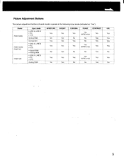
Model PVM-1344Q PVM-1342Q/ PVM-1341 PVM-1340 Input mode • LINE A, LINE B • Y/C • VTR Analog RGB Component • LINE A, LINE B • Y/C • VTR • Digital RGB • Analog RGB • LINE A, LINE B • Y/C • VTR Analog RGB APERTURE BRIGHT Yes Yes No Yes Yes Yes Yes Yes No Yes Yes Yes No Yes CHROMA Yes No Yes Yes No PHASE CONTRAST Yes _ (NTSC only) Yes No...
Model PVM-1344Q PVM-1342Q/ PVM-1341 PVM-1340 Input mode • LINE A, LINE B • Y/C • VTR Analog RGB Component • LINE A, LINE B • Y/C • VTR • Digital RGB • Analog RGB • LINE A, LINE B • Y/C • VTR Analog RGB APERTURE BRIGHT Yes Yes No Yes Yes Yes Yes Yes No Yes Yes Yes No Yes CHROMA Yes No Yes Yes No PHASE CONTRAST Yes _ (NTSC only) Yes No...

Operating Instructions
Page 10
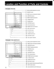
Location and Function of Parts and Controls Rear panel PVM-1344Q O0 (0) LINE A, LINE B connectors 2 Y/C-INPUT connectors _1 VTR input connectors T1 COLOR TEMP selector 05 COMPO/RGB selector LC • V HOLD control 1 EXT SYNC connectors 8 CTRL S connectors 1. ] ANALOG RGB/COMPONENT connectors, AUDIO IN connector Rear panel PVM-1342O/PVM-1341 O 006 O ie
Location and Function of Parts and Controls Rear panel PVM-1344Q O0 (0) LINE A, LINE B connectors 2 Y/C-INPUT connectors _1 VTR input connectors T1 COLOR TEMP selector 05 COMPO/RGB selector LC • V HOLD control 1 EXT SYNC connectors 8 CTRL S connectors 1. ] ANALOG RGB/COMPONENT connectors, AUDIO IN connector Rear panel PVM-1342O/PVM-1341 O 006 O ie
Operating Instructions
Page 11
... input signal fed through connection, connect to the analog RIG/B signal outputs of a video camera having no outputs. Connect to the video input for a VCR or another monitor by using a connecting cord (miniplug-,-.miniplug). 9 ANALOG RGB/COMPONENT connectors (BNC type) Ft/R-Y IN, G/Y IN, B/B-Y IN: To monitor the analog R/G/B signal, connect to the audio output of another monitor. When the cable is output from the Y channel. Connect to the VIDEO IN connector is connected to this connector. When the EXT SYNC button...
... input signal fed through connection, connect to the analog RIG/B signal outputs of a video camera having no outputs. Connect to the video input for a VCR or another monitor by using a connecting cord (miniplug-,-.miniplug). 9 ANALOG RGB/COMPONENT connectors (BNC type) Ft/R-Y IN, G/Y IN, B/B-Y IN: To monitor the analog R/G/B signal, connect to the audio output of another monitor. When the cable is output from the Y channel. Connect to the VIDEO IN connector is connected to this connector. When the EXT SYNC button...
Operating Instructions
Page 12
... a video camera. 12 Connect to the SYNC output of a video camera. To monitor the input signal fed through this connector, press the RGB button and keep the ANALOG/DIGITAL (EXT SYNC) button released. Connect to the output of a video camera. To monitor a signal fedthrough these connectors. 14 ANALOG RGB IN connectors (BNC type) R/G/B IN: Connect to the analog R/G/B outputs of a sync generator. Note For connection, be sure to use an optional SMF-520 connecting cable. 11 H CENT (horizontal centering) control When a digital R/G/B signal is monitored, turn...
... a video camera. 12 Connect to the SYNC output of a video camera. To monitor the input signal fed through this connector, press the RGB button and keep the ANALOG/DIGITAL (EXT SYNC) button released. Connect to the output of a video camera. To monitor a signal fedthrough these connectors. 14 ANALOG RGB IN connectors (BNC type) R/G/B IN: Connect to the analog R/G/B outputs of a sync generator. Note For connection, be sure to use an optional SMF-520 connecting cable. 11 H CENT (horizontal centering) control When a digital R/G/B signal is monitored, turn...
Operating Instructions
Page 13
... (Standard color bar signal of 75-percent chrominance) When the composite signal is fed to the G or Y channels, the monitor can be activated in the internal sync mode. 75 ohms terminated automatically with no cable connected to the output connector CTRL S: Minijack PVM-1342Q/PVM-1341 only EXT SYNC: BNC connector composite sync 1-4 Vp-p, negative, 75 ohms terminated automatically with no cable connected to the output connector ANALOG RGB: BNC connector...
... (Standard color bar signal of 75-percent chrominance) When the composite signal is fed to the G or Y channels, the monitor can be activated in the internal sync mode. 75 ohms terminated automatically with no cable connected to the output connector CTRL S: Minijack PVM-1342Q/PVM-1341 only EXT SYNC: BNC connector composite sync 1-4 Vp-p, negative, 75 ohms terminated automatically with no cable connected to the output connector ANALOG RGB: BNC connector...
Operating Instructions
Page 14
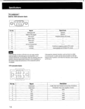
... function of Pin No. 6 is not used , set the internal switch on the Qd board to the A position, and feed the intensity control signal to Pin No. 6. Specifications Pin assignment DIGITAL RGB connector (9-pin) © ( O1OO2 O3OO4OO5o ) 6 789 Pin No. 1 2 3 4 5 6 7 8 9 Signal GND (ground) GND for the signal Red input Green input Blue input Intensity NC (no connection) H-SYNC V-SYNC Signal level Ground Ground Positive polarity (TTL level) t t t Positive or negative polarity (TTL level) Same polarity...
... function of Pin No. 6 is not used , set the internal switch on the Qd board to the A position, and feed the intensity control signal to Pin No. 6. Specifications Pin assignment DIGITAL RGB connector (9-pin) © ( O1OO2 O3OO4OO5o ) 6 789 Pin No. 1 2 3 4 5 6 7 8 9 Signal GND (ground) GND for the signal Red input Green input Blue input Intensity NC (no connection) H-SYNC V-SYNC Signal level Ground Ground Positive polarity (TTL level) t t t Positive or negative polarity (TTL level) Same polarity...
Operating Instructions
Page 15
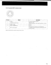
Description 1 Vp-p, sync negative, 75 ohms 300 mVp-p, burst Delay time between Y and C: within 0±100 nsec., 75 ohms Ground Ground Press the switch inside this slot. The signal from Y/C-INPUT connector has priority over the one from VTR (8-pin) connector. 15 YIC (VIC separate) INPUT connector (4-pin) 2 1 0 0 4 3 u 0 Pin No. 1 Y-input Signal 2 CHROMA sub-carrier-input 3 GND for Y-input 4 GND for CHROMA-input * Slot for internal switch Design and specifications subject to change without notice.
Description 1 Vp-p, sync negative, 75 ohms 300 mVp-p, burst Delay time between Y and C: within 0±100 nsec., 75 ohms Ground Ground Press the switch inside this slot. The signal from Y/C-INPUT connector has priority over the one from VTR (8-pin) connector. 15 YIC (VIC separate) INPUT connector (4-pin) 2 1 0 0 4 3 u 0 Pin No. 1 Y-input Signal 2 CHROMA sub-carrier-input 3 GND for Y-input 4 GND for CHROMA-input * Slot for internal switch Design and specifications subject to change without notice.


