Sony PVM-1341 Support and Manuals
Get Help and Manuals for this Sony item

View All Support Options Below
Free Sony PVM-1341 manuals!
Problems with Sony PVM-1341?
Ask a Question
Free Sony PVM-1341 manuals!
Problems with Sony PVM-1341?
Ask a Question
Sony PVM-1341 Videos

Sony PVM-1341 Professional Video Monitor Demo
Duration: 5:52
Total Views: 2,304
Duration: 5:52
Total Views: 2,304
Popular Sony PVM-1341 Manual Pages
Warranty Card - Page 2
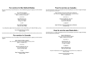
...to supply you with technical support:
Sony Technical Support URL: www.sony.com/displays/support
EMAIL: [email protected]
or write to :
Sony of Canada Ltd. Sony Authorized Service Locations 1-800-282-2848
For service in Canada:
For your convenience, Sony Electronics Inc. has established a group to supply you with technical support:
Sony Computer Products Support URL: www.sony.ca/sonyca...
Operating Instructions - Page 1
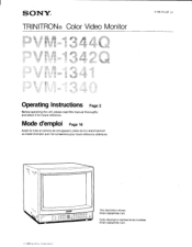
... mise en service de cet appareil, priere de lire attentivement ce mode d'emploi que Ion conservera pour toute reference ulterieure.
Cette illustration represente les modeles PVM-1342Q/PVM-1341.
© 1988 by Sony Corporation SONY®
TRINITRON® Color Video Monitor
3-786-761-27 (1)
Operating Instructions Page 2
Before operating the unit, please read this manual thoroughly and retain...
Operating Instructions - Page 2
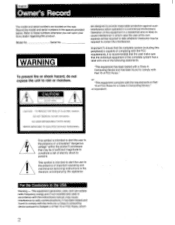
...SERVICEABLE PARTS INSIDE. Model No. CAUTION
RISK OF ELECTRIC SHOCK DO NOT OPEN
are located on the rear. "This equipment has been tested with a Class A Computing Device and has been found to comply with the instructions manual... you call upon your Sony dealer regarding this peripheral)...installed and used in Part 15 of FCC Rules for a Class A computing device pursuant to Subpart J of Part...
Operating Instructions - Page 3
... any questions about this unit, contact your authorized Sony dealer.
000000
O
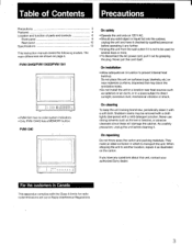
For the customers in a ...emissions set out in which to another location, repack it with a mild detergent solution. On installation
&#...parts and controls
6
Front panel
6
Rear panel
10
Specifications
13
This instruction manual covers the following models. When shipping the unit to transport the unit. PVM...
Operating Instructions - Page 4
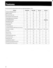
Features
Automatic white balance circuit
SMPTE-C phosphor
Black-tinted Trinitron tube
Super Fine Pitch Trinitron picture tube
Analog RGB/component input/output
Analog RGB input/output
...Yes
Yes
No
Yes
Yes
Yes
Yes
Yes
Yes
Yes
Yes
PVM-1341 Yes No
- Features
This chart shows the various features which your model has (indicated as "Yes"). Horizontal/vertical delay mode
Users control memory ...
Operating Instructions - Page 5
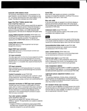
... cable. Super Fine Pitch Trinitron picutre tube (PVM-1344Q/PVM-1342Q only) The Super Fine Pitch Trinitron picture tube (0.25 mm aperture grill) gives high resolution picture. WC input connector The video signal split into the chrominance signal (C) and the luminance signal (Y) can be operated on mounting, see the appropriate instruction manual.
5 Automatic termination of BNC...
Operating Instructions - Page 6
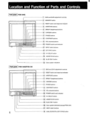
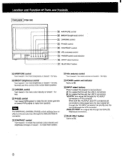
... buttons
9 VOL (volume) buttons
1101 POWER switch and indicator
13 H-V DELAY button 1141 UNDER SCAN button 151 BLUE ONLY button 16 Color system indicators (except PVM-1341) 17 INPUT select buttons 18 ANALOG/DIGITAL (EXT SYNC)button
Location and Function of Parts and Controls
Front panel PVM-1344O
rfilff:131E33938 a
Front panel...
Operating Instructions - Page 7
...return the PHASE, CHROMA, BRIGHT and APERTURE control settings to make the skin tones greenish or PUR (purple) to turn the monitor on the sync signal from the displayed composite video ... through the Y/C-INPUT connector has priority over the one fed through the LINE A connectors.
for PVM-1444OM).
the vertical signal is pressed. 4 APERTURE buttons Press + for a signal fed through ...
Operating Instructions - Page 8
...signal fed through the Y/C-INPUT
connectors or VTR connector. Normally set this contra' at the center detent position.
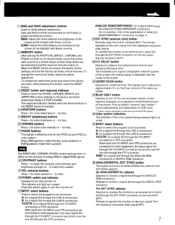
When both ...: for more volume or toward - Location and Function of Parts and Controls
Front panel PVM-134O
U U fi) 0 0 0
2
19 APERTURE...as El.
261INPUT select buttons
Press to select the program to be monitored.
for a signal fed through the LINE A connectors. A: for...
Operating Instructions - Page 9
Model PVM-1344Q
PVM-1342Q/ PVM-1341
PVM-1340
Input mode
• LINE A, LINE B • Y/C • VTR
Analog RGB
Component
• LINE A, LINE B • Y/C • VTR
• Digital RGB • Analog...NTSC only)
No
No
Yes
VOL Yes Yes Yes Yes
No
Yes No
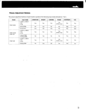
9 Picture Adjustment Buttons
The picture adjustment buttons of each monitor operate in the following input mode (indicated as "Yes").
Operating Instructions - Page 10
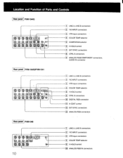
Location and Function of Parts and Controls
Rear panel PVM-1344Q
O0
(0)
LINE A, LINE B connectors 2 Y/C-INPUT connectors
_1 VTR input connectors T1 COLOR TEMP selector
05 COMPO/RGB selector
LC • V HOLD control
1 EXT SYNC connectors 8 CTRL S connectors 1. ] ANALOG RGB/COMPONENT connectors,
AUDIO IN connector
Rear panel PVM-1342O/PVM-1341
O 006 O ie
Operating Instructions - Page 11
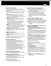
...the front panel.
3 VTR input connectors (8-pin) Line input for a VCR or another monitor. Set the COMPO/RGB selector on the rear panel to RGB and press the ANALOG RGB/COMPONENT ... selector Set to COMPO to no sync signal.
Connect to the VIDEO IN connector is connected to this connector. IN: Connect to the R-YN/B-Y component signal outputs of a Sony BetaCam video camera. To monitor the ...
Operating Instructions - Page 12
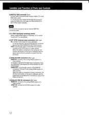
...SMF-520 connecting cable.
11 H CENT (horizontal centering) control When a digital R/G/B signal is monitored, turn to center the picture if it is connected to the output of a video camera. When... the ANALOG/DIGITAL (EXT SYNC) button. SYNC IN: Connect to the analog R/G/B inputs of Parts and Controls
1101DIGITAL RGB connector (9-pin) Connect with a microcomputer having a digital (TTL level) ...
Operating Instructions - Page 13
...;6 dB (Standard color bar signal of CRT effective screen area
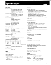
H. Specifications
Video signal
Frequency response Line input: More than 7 MHz (-3 dB... MHz equiband
Chrominance/luminance
Time error
Composite: Less than ±100...monitor can be activated in the internal sync mode. 75 ohms terminated automatically with no cable connected to the output connector
CTRL S: Minijack
PVM-1342Q/PVM-1341...
Operating Instructions - Page 14
... 1 Vp-p, sync negative, 75 ohms GND ---.
GND GND GND GND
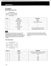
14 With this setting, when the positive intensity signal synchronized to the characters on the Qd board to the A position, and feed the intensity control signal to the GND. Specifications
Pin assignment DIGITAL RGB connector (9-pin)
© ( O1OO2 O3OO4OO5o ) 6 789
Pin No...
Sony PVM-1341 Reviews
We have not received any reviews for Sony yet.