
Warranty Card
Page 2
... dont vous pourriez avoir besoin : Appui technique Sony URL: www.sony.com/displays/support EMAIL: [email protected] ou écrivez à : Sony Electronics, Inc. 12451 Gateway Blvd. Centre de service autorisé par Sony 1-800-282-2848 has established a group to supply you with technical support: Sony Computer Products Support URL: www.sony.ca/sonyca/customersupport_contactus.shtml EMAIL: it_help...
... dont vous pourriez avoir besoin : Appui technique Sony URL: www.sony.com/displays/support EMAIL: [email protected] ou écrivez à : Sony Electronics, Inc. 12451 Gateway Blvd. Centre de service autorisé par Sony 1-800-282-2848 has established a group to supply you with technical support: Sony Computer Products Support URL: www.sony.ca/sonyca/customersupport_contactus.shtml EMAIL: it_help...
Operating Instructions
Page 1
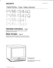
cam OOOO Deno ww, 000000 0 0 00000 This illustration shows PVM-1342Q/PVM-1341. SONY® TRINITRON® Color Video Monitor 3-786-761-27 (1) Operating Instructions Page 2 Before operating the unit, please read this manual thoroughly and retain it for future reference. Mode d'emploi Page 16 Avant la mise en service de cet appareil, priere de lire attentivement ce mode d'emploi que Ion conservera pour toute reference ulterieure. Cette illustration represente les modeles PVM-1342Q/PVM-1341. © 1988 by Sony Corporation
cam OOOO Deno ww, 000000 0 0 00000 This illustration shows PVM-1342Q/PVM-1341. SONY® TRINITRON® Color Video Monitor 3-786-761-27 (1) Operating Instructions Page 2 Before operating the unit, please read this manual thoroughly and retain it for future reference. Mode d'emploi Page 16 Avant la mise en service de cet appareil, priere de lire attentivement ce mode d'emploi que Ion conservera pour toute reference ulterieure. Cette illustration represente les modeles PVM-1342Q/PVM-1341. © 1988 by Sony Corporation
Operating Instructions
Page 2
.... This equipment generates, uses, and can radiate radio frequency energy and if not installed and used in accordance with the requirements in Part 15 of FCC Rules for a Class A computing device pursuant to Subpart J of Part 15 of the following statements. This symbol is likely to cause interference in which 2 English Owner's Record The model and serial numbers are designed to...
.... This equipment generates, uses, and can radiate radio frequency energy and if not installed and used in accordance with the requirements in Part 15 of FCC Rules for a Class A computing device pursuant to Subpart J of Part 15 of the following statements. This symbol is likely to cause interference in which 2 English Owner's Record The model and serial numbers are designed to...
Operating Instructions
Page 3
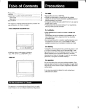
... direct sunlight, excessive dust, mechanical vibration or shock. PVM-13440/PVM-13420/PVM-1341 L___ rr. 2E,LAoMaoPou]; • PVM-1341 has no color system indicators. • Only PVM-1344O has a MEMORY button. Table of Contents Precautions Precautions 3 Features 4 Location and function of parts and controls 6 Front panel 6 Rear panel 10 Specifications 13 This instruction manual covers the following models. The main differences are shown-on 120 V AC...
... direct sunlight, excessive dust, mechanical vibration or shock. PVM-13440/PVM-13420/PVM-1341 L___ rr. 2E,LAoMaoPou]; • PVM-1341 has no color system indicators. • Only PVM-1344O has a MEMORY button. Table of Contents Precautions Precautions 3 Features 4 Location and function of parts and controls 6 Front panel 6 Rear panel 10 Specifications 13 This instruction manual covers the following models. The main differences are shown-on 120 V AC...
Operating Instructions
Page 4
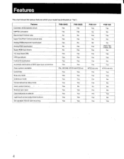
...sync input Color temperature selector Light-touch picture adjustment buttons EIA standard 19-inch rack mounting PVM-1344O PVM...Yes Yes PVM-1341 Yes No - Horizontal/vertical delay mode Users control memory &#...white balance circuit SMPTE-C phosphor Black-tinted Trinitron tube Super Fine Pitch Trinitron picture tube Analog RGB/component input/output Analog RGB input/output Digital RGB input (9-pin) Y/C input (4-pin DIN) VTR input (8-pin) Control S input/output Automatic termination of BNC-type input connectors Color systems available Comb filter Blue only mode Underscan mode...
...sync input Color temperature selector Light-touch picture adjustment buttons EIA standard 19-inch rack mounting PVM-1344O PVM...Yes Yes PVM-1341 Yes No - Horizontal/vertical delay mode Users control memory &#...white balance circuit SMPTE-C phosphor Black-tinted Trinitron tube Super Fine Pitch Trinitron picture tube Analog RGB/component input/output Analog RGB input/output Digital RGB input (9-pin) Y/C input (4-pin DIN) VTR input (8-pin) Control S input/output Automatic termination of BNC-type input connectors Color systems available Comb filter Blue only mode Underscan mode...
Operating Instructions
Page 5
... by touching the buttons lightly. Horizontal/vertical delay mode (except PVM-1340) The horizontal and vertical sync signals can be input through this connector. Color temperature selector Color temperature of the monitor. External sync input (except PVM-1340) When the EXT SYNC (or ANALOG/DIGITAL (EXT SYNC)) button is selectable with the COLOR TEMP selector. This allows an extended use of either 9,300°K or 6,500°K is depressed, the monitor can be displayed with a single cable. The signals are...
... by touching the buttons lightly. Horizontal/vertical delay mode (except PVM-1340) The horizontal and vertical sync signals can be input through this connector. Color temperature selector Color temperature of the monitor. External sync input (except PVM-1340) When the EXT SYNC (or ANALOG/DIGITAL (EXT SYNC)) button is selectable with the COLOR TEMP selector. This allows an extended use of either 9,300°K or 6,500°K is depressed, the monitor can be displayed with a single cable. The signals are...
Operating Instructions
Page 6
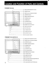
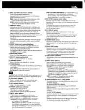
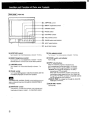
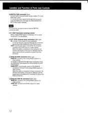
...of Parts and Controls Front panel PVM-1344O rfilff:131E33938 a Front panel PVM-1342QIPVM-1341- r LEM 6 BIAS and GAIN adjustment controls J MEMORY button 13 1 RESET button and response indicator 41 APERTURE buttons BRIGHT (brightness) buttons 6 CHROMA buttons FT PHASE buttons CONTRAST buttons 11 VOL (volume) buttons 10 POWER switch and indicator 11 INPUT select buttons 12 EXT SYNC button 13 H-V DELAY button 1141 UNDER SCAN button 15 BLUE ONLY button 16 Color system indicators 1 BIAS and GAIN adjustment controls 13 1 RESET button and response indicator 141 APERTURE buttons 5 BRIGHT (brightness...
...of Parts and Controls Front panel PVM-1344O rfilff:131E33938 a Front panel PVM-1342QIPVM-1341- r LEM 6 BIAS and GAIN adjustment controls J MEMORY button 13 1 RESET button and response indicator 41 APERTURE buttons BRIGHT (brightness) buttons 6 CHROMA buttons FT PHASE buttons CONTRAST buttons 11 VOL (volume) buttons 10 POWER switch and indicator 11 INPUT select buttons 12 EXT SYNC button 13 H-V DELAY button 1141 UNDER SCAN button 15 BLUE ONLY button 16 Color system indicators 1 BIAS and GAIN adjustment controls 13 1 RESET button and response indicator 141 APERTURE buttons 5 BRIGHT (brightness...
Operating Instructions
Page 7
... and contrast of the screen at the highlight with these controls. When the RESET button is effective only for less. 7 PHASE buttons This button is pressed, the above operations. for the NTSC3.5t3 and NTSC4.4.3 color system. A blue signal is displayed in red. Release to turn the monitor off the red and green signals. MEMORY button After setting the APERTURE, BRIGHT, CHROMA, and PHASE controls to video equipment, the input signal fed through the Y/C-INPUT connector...
... and contrast of the screen at the highlight with these controls. When the RESET button is effective only for less. 7 PHASE buttons This button is pressed, the above operations. for the NTSC3.5t3 and NTSC4.4.3 color system. A blue signal is displayed in red. Release to turn the monitor off the red and green signals. MEMORY button After setting the APERTURE, BRIGHT, CHROMA, and PHASE controls to video equipment, the input signal fed through the Y/C-INPUT connector...
Operating Instructions
Page 8
to be monitored. for less. (201BRIGHT (brightness) control Turn toward + for more color intensity or toward - ACHROMA control Turn toward + for more brightness or toward - ANALOG RGB: for a signal fed through the VTR connector. Location and Function of Parts and Controls Front panel PVM-134O U U fi) 0 0 0 2 19 APERTURE control 20 BRIGHT (brightness) control 21 CHROMA control 0 PHASE control 231 CONTRAST control 1241 VOL (volume) control 1251 POWER switch and indicator a INPUT select buttons 27 BLUE ONLY button 1191APERTURE control Turn toward + for more volume or toward...
to be monitored. for less. (201BRIGHT (brightness) control Turn toward + for more color intensity or toward - ACHROMA control Turn toward + for more brightness or toward - ANALOG RGB: for a signal fed through the VTR connector. Location and Function of Parts and Controls Front panel PVM-134O U U fi) 0 0 0 2 19 APERTURE control 20 BRIGHT (brightness) control 21 CHROMA control 0 PHASE control 231 CONTRAST control 1241 VOL (volume) control 1251 POWER switch and indicator a INPUT select buttons 27 BLUE ONLY button 1191APERTURE control Turn toward + for more volume or toward...
Operating Instructions
Page 9
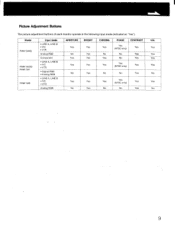
Picture Adjustment Buttons The picture adjustment buttons of each monitor operate in the following input mode (indicated as "Yes"). Model PVM-1344Q PVM-1342Q/ PVM-1341 PVM-1340 Input mode • LINE A, LINE B • Y/C • VTR Analog RGB Component • LINE A, LINE B • Y/C • VTR • Digital RGB • Analog RGB • LINE A, LINE B • Y/C • VTR Analog RGB APERTURE BRIGHT Yes Yes No Yes Yes Yes Yes Yes No Yes Yes Yes No Yes CHROMA Yes...
Picture Adjustment Buttons The picture adjustment buttons of each monitor operate in the following input mode (indicated as "Yes"). Model PVM-1344Q PVM-1342Q/ PVM-1341 PVM-1340 Input mode • LINE A, LINE B • Y/C • VTR Analog RGB Component • LINE A, LINE B • Y/C • VTR • Digital RGB • Analog RGB • LINE A, LINE B • Y/C • VTR Analog RGB APERTURE BRIGHT Yes Yes No Yes Yes Yes Yes Yes No Yes Yes Yes No Yes CHROMA Yes...
Operating Instructions
Page 10
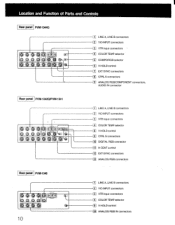
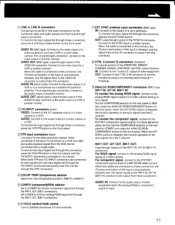
Location and Function of Parts and Controls Rear panel PVM-1344Q O0 (0) LINE A, LINE B connectors 2 Y/C-INPUT connectors _1 VTR input connectors T1 COLOR TEMP selector 05 COMPO/RGB selector LC • V HOLD control 1 EXT SYNC connectors 8 CTRL S connectors 1. ] ANALOG RGB/COMPONENT connectors, AUDIO IN connector Rear panel PVM-1342O/PVM-1341 O 006 O ie
Location and Function of Parts and Controls Rear panel PVM-1344Q O0 (0) LINE A, LINE B connectors 2 Y/C-INPUT connectors _1 VTR input connectors T1 COLOR TEMP selector 05 COMPO/RGB selector LC • V HOLD control 1 EXT SYNC connectors 8 CTRL S connectors 1. ] ANALOG RGB/COMPONENT connectors, AUDIO IN connector Rear panel PVM-1342O/PVM-1341 O 006 O ie
Operating Instructions
Page 11
..., BRIGHT, CHROMA, PHASE, CONTRAST and VOL control buttons. For component signal, connect to the analog RIG/B signal outputs of a video camera having no outputs. AUDIO OUT (phono jack): Loop-through outputs of the R/R-Y IN, G/Y IN, B/B-Y IN connectors. OUT: Connect to the CTRL S IN connector of another monitor by using a connecting cord (miniplug-,-.miniplug). 9 ANALOG RGB/COMPONENT connectors (BNC type) Ft/R-Y IN, G/Y IN, B/B-Y IN: To monitor the analog R/G/B signal, connect to the R-Y/Y/B-Y component signal inputs of a BETACAM video...
..., BRIGHT, CHROMA, PHASE, CONTRAST and VOL control buttons. For component signal, connect to the analog RIG/B signal outputs of a video camera having no outputs. AUDIO OUT (phono jack): Loop-through outputs of the R/R-Y IN, G/Y IN, B/B-Y IN connectors. OUT: Connect to the CTRL S IN connector of another monitor by using a connecting cord (miniplug-,-.miniplug). 9 ANALOG RGB/COMPONENT connectors (BNC type) Ft/R-Y IN, G/Y IN, B/B-Y IN: To monitor the analog R/G/B signal, connect to the R-Y/Y/B-Y component signal inputs of a BETACAM video...
Operating Instructions
Page 12
... a video camera. SYNC IN: Connect to the analog R/G/B inputs of a video camera. 12 To monitor the sync signal fed through this connector, depress the ANALOG/DIGITAL (EXT SYNC) button. Connect to the analog R/G/B outputs of a sync generator. To monitor a signal fedthrough these connectors. 14 ANALOG RGB IN connectors (BNC type) R/G/B IN: Connect to the SYNC input of the SYNC IN connector. Note For connection, be sure to use an optional SMF-520 connecting cable. 11 H CENT (horizontal centering) control When a digital R/G/B signal is monitored, turn to center the picture...
... a video camera. SYNC IN: Connect to the analog R/G/B inputs of a video camera. 12 To monitor the sync signal fed through this connector, depress the ANALOG/DIGITAL (EXT SYNC) button. Connect to the analog R/G/B outputs of a sync generator. To monitor a signal fedthrough these connectors. 14 ANALOG RGB IN connectors (BNC type) R/G/B IN: Connect to the SYNC input of the SYNC IN connector. Note For connection, be sure to use an optional SMF-520 connecting cable. 11 H CENT (horizontal centering) control When a digital R/G/B signal is monitored, turn to center the picture...
Operating Instructions
Page 13
... (Standard color bar signal of 75-percent chrominance) When the composite signal is fed to the G or Y channels, the monitor can be activated in the internal sync mode. 75 ohms terminated automatically with no cable connected to the output connector CTRL S: Minijack PVM-1342Q/PVM-1341 only EXT SYNC: BNC connector composite sync 1-4 Vp-p, negative, 75 ohms terminated automatically with no cable connected to the output connector ANALOG RGB: BNC connector...
... (Standard color bar signal of 75-percent chrominance) When the composite signal is fed to the G or Y channels, the monitor can be activated in the internal sync mode. 75 ohms terminated automatically with no cable connected to the output connector CTRL S: Minijack PVM-1342Q/PVM-1341 only EXT SYNC: BNC connector composite sync 1-4 Vp-p, negative, 75 ohms terminated automatically with no cable connected to the output connector ANALOG RGB: BNC connector...
Operating Instructions
Page 14
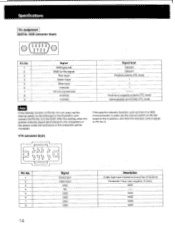
... ohms GND ---. Specifications Pin assignment DIGITAL RGB connector (9-pin) © ( O1OO2 O3OO4OO5o ) 6 789 Pin No. 1 2 3 4 5 6 7 8 9 Signal GND (ground) GND for the signal Red input Green input Blue input Intensity NC (no connection) H-SYNC V-SYNC Signal level Ground Ground Positive polarity (TTL level) t t t Positive or negative polarity (TTL level) Same polarity as that of Pin No. 6 is not used , set the internal switch on the Qd board to the B position, and connect the Pin No...
... ohms GND ---. Specifications Pin assignment DIGITAL RGB connector (9-pin) © ( O1OO2 O3OO4OO5o ) 6 789 Pin No. 1 2 3 4 5 6 7 8 9 Signal GND (ground) GND for the signal Red input Green input Blue input Intensity NC (no connection) H-SYNC V-SYNC Signal level Ground Ground Positive polarity (TTL level) t t t Positive or negative polarity (TTL level) Same polarity as that of Pin No. 6 is not used , set the internal switch on the Qd board to the B position, and connect the Pin No...

Operating Instructions
Page 15
The signal from Y/C-INPUT connector has priority over the one from VTR (8-pin) connector. 15 Description 1 Vp-p, sync negative, 75 ohms 300 mVp-p, burst Delay time between Y and C: within 0±100 nsec., 75 ohms Ground Ground Press the switch inside this slot. YIC (VIC separate) INPUT connector (4-pin) 2 1 0 0 4 3 u 0 Pin No. 1 Y-input Signal 2 CHROMA sub-carrier-input 3 GND for Y-input 4 GND for CHROMA-input * Slot for internal switch Design and specifications subject to change without notice.
The signal from Y/C-INPUT connector has priority over the one from VTR (8-pin) connector. 15 Description 1 Vp-p, sync negative, 75 ohms 300 mVp-p, burst Delay time between Y and C: within 0±100 nsec., 75 ohms Ground Ground Press the switch inside this slot. YIC (VIC separate) INPUT connector (4-pin) 2 1 0 0 4 3 u 0 Pin No. 1 Y-input Signal 2 CHROMA sub-carrier-input 3 GND for Y-input 4 GND for CHROMA-input * Slot for internal switch Design and specifications subject to change without notice.


