Quick Start Guide
Page 12
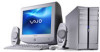
VAIO Digital Studio Computer Quick Start Unpacking your Computer Your computer may vary, depending on the accessories supplied with all of the accessories shown, depending on supplied accessories. 12 See the online specifications sheet for details on the system configuration you purchased. Computer and supplied accessories System unit (PCV...-RZ series model shown) Speakers* (PCVA-SP3A) with Speaker power cable Speakers* (PCVA-SP4) with Speaker power cable Power cord Mouse Modem cable ...
VAIO Digital Studio Computer Quick Start Unpacking your Computer Your computer may vary, depending on the accessories supplied with all of the accessories shown, depending on supplied accessories. 12 See the online specifications sheet for details on the system configuration you purchased. Computer and supplied accessories System unit (PCV...-RZ series model shown) Speakers* (PCVA-SP3A) with Speaker power cable Speakers* (PCVA-SP4) with Speaker power cable Power cord Mouse Modem cable ...

Quick Start Guide
Page 17
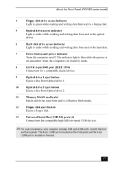
About the Front Panel (PCV-RZ series model) 4 Floppy disk drive access indicator Light is green while reading and writing data from and to a floppy disk. 5 Power indicator Light is blue while the power is on. 6 Power switch Turns the computer on and off. 7 Stand by indicator Light is red when the computer is placed in Stand...
About the Front Panel (PCV-RZ series model) 4 Floppy disk drive access indicator Light is green while reading and writing data from and to a floppy disk. 5 Power indicator Light is blue while the power is on. 6 Power switch Turns the computer on and off. 7 Stand by indicator Light is red when the computer is placed in Stand...
Quick Start Guide
Page 19
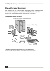
The icons on the back panel locate and identify the ports on your computer contains the ports for a parallel device, such as a printer or scanner. 19 Back panel (PCV-RZ series model) MONITOR USB MIC HEADPHONES LINE IN MONITOR AUDIO S VIDEO/VIDEO AUDIO S VIDEO/VIDEO -...power cord. 2 Mouse port Connection for a PS/2® mouse. 3 Keyboard port Connection for a PS/2 keyboard. 4 Printer port Connection for supplied and optional accessories. VIDEO OUTPUT - - About the Back Panel (PCV-RZ series model) About the Back Panel (PCV-RZ series model) The back panel of your computer...
The icons on the back panel locate and identify the ports on your computer contains the ports for a parallel device, such as a printer or scanner. 19 Back panel (PCV-RZ series model) MONITOR USB MIC HEADPHONES LINE IN MONITOR AUDIO S VIDEO/VIDEO AUDIO S VIDEO/VIDEO -...power cord. 2 Mouse port Connection for a PS/2® mouse. 3 Keyboard port Connection for a PS/2 keyboard. 4 Printer port Connection for supplied and optional accessories. VIDEO OUTPUT - - About the Back Panel (PCV-RZ series model) About the Back Panel (PCV-RZ series model) The back panel of your computer...
Quick Start Guide
Page 20
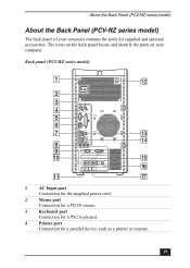
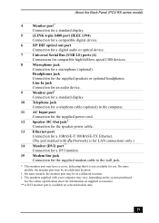
VAIO Digital Studio Computer Quick Start 5 Monitor port* Connection for a standard display. 6 i.LINK 6-pin S400 port (IEEE 1394) Connection and power for a compatible digital device such as a Sony Digital Handycam® camcorder. 7 Universal Serial Bus (USB 2.0) ports (4) Connections for compatible high/full...; Connection for a DVI monitor. 11 Telephone jack Connection for a telephone cable (optional) to the computer. 12 Speaker DC Out jack** Connection for the speaker power cable. 13 S/P DIF optical out port Connection for a digital audio or optical device. 14 Ethernet port...
VAIO Digital Studio Computer Quick Start 5 Monitor port* Connection for a standard display. 6 i.LINK 6-pin S400 port (IEEE 1394) Connection and power for a compatible digital device such as a Sony Digital Handycam® camcorder. 7 Universal Serial Bus (USB 2.0) ports (4) Connections for compatible high/full...; Connection for a DVI monitor. 11 Telephone jack Connection for a telephone cable (optional) to the computer. 12 Speaker DC Out jack** Connection for the speaker power cable. 13 S/P DIF optical out port Connection for a digital audio or optical device. 14 Ethernet port...
Quick Start Guide
Page 27
The 4-pin i.LINK port is located on the front panel and the 6-pin i.LINK port is located on /off. About the Front Panel (PCV-RX series model) 4 Floppy disk drive access indicator Light is green while reading and writing data from and to a floppy disk. 5 Optical drive access ... Light is amber while reading and writing data from and to the hard disk. 7 Power button and power indicator Turns the computer on the back. 27 The indicator light is blue while the power is on and amber when the computer is in Stand by mode. 8 i.LINK 4-pin S400 port (IEEE 1394) Connection for a ...
The 4-pin i.LINK port is located on the front panel and the 6-pin i.LINK port is located on /off. About the Front Panel (PCV-RX series model) 4 Floppy disk drive access indicator Light is green while reading and writing data from and to a floppy disk. 5 Optical drive access ... Light is amber while reading and writing data from and to the hard disk. 7 Power button and power indicator Turns the computer on the back. 27 The indicator light is blue while the power is on and amber when the computer is in Stand by mode. 8 i.LINK 4-pin S400 port (IEEE 1394) Connection for a ...
Quick Start Guide
Page 29
... display. 10 Telephone jack Connection for a telephone cable (optional) to the computer. 11 AC Input port Connection for the supplied power cord. 12 Speaker DC Out jack‡ Connection for the speaker power cable. 13 Ethernet port Connection for a 10BASE-T/100BASE-TX Ethernet. (The port... marked with your computer may have a cover, indicating that it is not available for information on supplied accessories. ** A DVI monitor port is available on the system purchased. About the Back Panel (PCV-RX series model) 4 Monitor port* Connection for a ...
... display. 10 Telephone jack Connection for a telephone cable (optional) to the computer. 11 AC Input port Connection for the supplied power cord. 12 Speaker DC Out jack‡ Connection for the speaker power cable. 13 Ethernet port Connection for a 10BASE-T/100BASE-TX Ethernet. (The port... marked with your computer may have a cover, indicating that it is not available for information on supplied accessories. ** A DVI monitor port is available on the system purchased. About the Back Panel (PCV-RX series model) 4 Monitor port* Connection for a ...

Quick Start Guide
Page 33
Connecting a Display (Monitor) To connect a DVI display (PCV-RZ series model) ✍ Install your equipment so that you can easily reach the power outlet in the event of an emergency. 33
Connecting a Display (Monitor) To connect a DVI display (PCV-RZ series model) ✍ Install your equipment so that you can easily reach the power outlet in the event of an emergency. 33
Quick Start Guide
Page 34
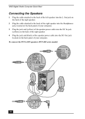
To connect the PCVA-SP4 speakers (PCV-RZ series model) USB 4 34 VAIO Digital Studio Computer Quick Start Connecting the Speakers 1 Plug the cable attached to the back of the left speaker into the L Out jack on the back of the ... the cable attached to the back of the right speaker into the Headphones jack, located on the back panel of your computer. 3 Plug the jack end (yellow) of the speaker power cable into the DC In jack (yellow) on the back of the right speaker. 4 Plug the jack end (black) of the...
To connect the PCVA-SP4 speakers (PCV-RZ series model) USB 4 34 VAIO Digital Studio Computer Quick Start Connecting the Speakers 1 Plug the cable attached to the back of the left speaker into the L Out jack on the back of the ... the cable attached to the back of the right speaker into the Headphones jack, located on the back panel of your computer. 3 Plug the jack end (yellow) of the speaker power cable into the DC In jack (yellow) on the back of the right speaker. 4 Plug the jack end (black) of the...
Quick Start Guide
Page 38
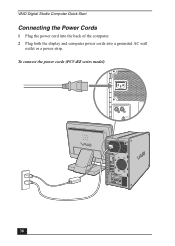
VAIO Digital Studio Computer Quick Start Connecting the Power Cords 1 Plug the power cord into the back of the computer. 2 Plug both the display and computer power cords into a grounded AC wall outlet or a power strip. To connect the power cords (PCV-RZ series model) KEYBOARD MOUSE PRINTER 38
VAIO Digital Studio Computer Quick Start Connecting the Power Cords 1 Plug the power cord into the back of the computer. 2 Plug both the display and computer power cords into a grounded AC wall outlet or a power strip. To connect the power cords (PCV-RZ series model) KEYBOARD MOUSE PRINTER 38

Quick Start Guide
Page 39
To turn on your computer (PCV-RZ series model with PCVA-SP3A speakers shown) 39 Turning On your Computer Turning On your Computer When you start your system for the first time, your computer may detect new equipment and display a dialog box that prompts you to turn on the power. Respond to this prompt immediately. 1 Press the power button on the computer to turn on the power. 2 Press the power button on the display to turn on the power. 3 Press the power button on the right speaker to restart your computer (PCV-RX series model with PCVA-SP4 speakers) To turn on your computer.
To turn on your computer (PCV-RZ series model with PCVA-SP3A speakers shown) 39 Turning On your Computer Turning On your Computer When you start your system for the first time, your computer may detect new equipment and display a dialog box that prompts you to turn on the power. Respond to this prompt immediately. 1 Press the power button on the computer to turn on the power. 2 Press the power button on the display to turn on the power. 3 Press the power button on the right speaker to restart your computer (PCV-RX series model with PCVA-SP4 speakers) To turn on your computer.
Quick Start Guide
Page 42
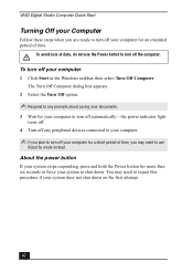
...the power indicator light turns off. 4 Turn off any peripheral devices connected to your computer. ✍ If you plan to turn off your computer for a short period of time. To turn off your system to shut down on the first attempt. 42 VAIO Digital Studio Computer Quick Start Turning Off your Computer ...Follow these steps when you may need to repeat this procedure if your system does not shut down . You may want to use the Power button to turn off the...
...the power indicator light turns off. 4 Turn off any peripheral devices connected to your computer. ✍ If you plan to turn off your computer for a short period of time. To turn off your system to shut down on the first attempt. 42 VAIO Digital Studio Computer Quick Start Turning Off your Computer ...Follow these steps when you may need to repeat this procedure if your system does not shut down . You may want to use the Power button to turn off the...
Quick Start Guide
Page 44
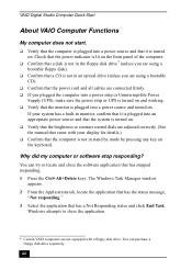
... close the application. * Certain VAIO computers are not equipped with your display for details.) ❑ Confirm that the computer is turned on the keyboard. VAIO Digital Studio Computer Quick Start About VAIO Computer Functions My computer does not start. ❑ Verify that the computer is plugged into a power source and turned on. Check that the power indicator is lit on the...
... close the application. * Certain VAIO computers are not equipped with your display for details.) ❑ Confirm that the computer is turned on the keyboard. VAIO Digital Studio Computer Quick Start About VAIO Computer Functions My computer does not start. ❑ Verify that the computer is plugged into a power source and turned on. Check that the power indicator is lit on the...
Quick Start Guide
Page 45
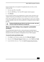
... the Alt+F4 keys. Pressing and holding the power button for more than six seconds, may result in the text, "View the VAIO® Computer Specifications..." 45 If the software application continues to stop responding or causes your VAIO computer. You can I find details about the drives,... cards, and memory modules that are installed on your system by pressing and holding the power button for more than six seconds. About VAIO Computer Functions If your computer does not respond or...
... the Alt+F4 keys. Pressing and holding the power button for more than six seconds, may result in the text, "View the VAIO® Computer Specifications..." 45 If the software application continues to stop responding or causes your VAIO computer. You can I find details about the drives,... cards, and memory modules that are installed on your system by pressing and holding the power button for more than six seconds. About VAIO Computer Functions If your computer does not respond or...
Quick Start Guide
Page 58
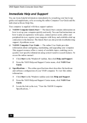
... space, connect power cords, cables and peripheral devices, register your computer with these support options: ❑ VAIO® Computer Quick Start - To access the online manual: 1 Click Start in the text, "View the VAIO® Computer Specifications..." 58 Your computer is supplied with Sony, and establish ...a dial-up your hard copy guides and supplements, or by accessing the online Computer User Guide and the individual software Help files. The ...
... space, connect power cords, cables and peripheral devices, register your computer with these support options: ❑ VAIO® Computer Quick Start - To access the online manual: 1 Click Start in the text, "View the VAIO® Computer Specifications..." 58 Your computer is supplied with Sony, and establish ...a dial-up your hard copy guides and supplements, or by accessing the online Computer User Guide and the individual software Help files. The ...
System Reference Manual
Page 11
Configuring Your System 15 Accessing the BIOS Setup Utility 16 Changing Power Management Settings 17 xi Contents NOTICE ...ii Owner's Record iii Safety Information and Caution iv Regulatory Information vii FCC Part...viii Telephone Consumer Guidelines (Canada viii Disposal of Lithium Battery ix Industry Canada Notice x Avis de l'Industrie Canada x Chapter 1 - Identifying Components 1 Front View (PCV-RZ Series model 2 Drives ...3 Buttons and Switches 4 Indicators 5 Connectors (Models Equipped with Giga Pocket Features)..........6 Rear View (Model Equipped with Giga Pocket Features 7...
Configuring Your System 15 Accessing the BIOS Setup Utility 16 Changing Power Management Settings 17 xi Contents NOTICE ...ii Owner's Record iii Safety Information and Caution iv Regulatory Information vii FCC Part...viii Telephone Consumer Guidelines (Canada viii Disposal of Lithium Battery ix Industry Canada Notice x Avis de l'Industrie Canada x Chapter 1 - Identifying Components 1 Front View (PCV-RZ Series model 2 Drives ...3 Buttons and Switches 4 Indicators 5 Connectors (Models Equipped with Giga Pocket Features)..........6 Rear View (Model Equipped with Giga Pocket Features 7...
System Reference Manual
Page 12
...Memory Module (DDR-DIMM) Slots 52 Power Supply and Aux Power Headers 53 CLR CMOS Jumper 55 Chapter 5 - Upgrading and Maintaining Components 23 Removing the Side Panel 24 To remove the side panel (PCV-RZ series model 24 To remove the side panel (PCV-RX series model 25 Replacing the Side... Cover 42 Covering an Open I/O Slot 43 Installing an Additional Hard Disk Drive 44 To identify additional hard disk space 48 Removing the Power Supply (PCV-RX series models 49 Replacing the Power Supply (PCV-RX series model 50 Chapter 4 - xii VAIO Digital Studio System Reference Manual Chapter 3 -
...Memory Module (DDR-DIMM) Slots 52 Power Supply and Aux Power Headers 53 CLR CMOS Jumper 55 Chapter 5 - Upgrading and Maintaining Components 23 Removing the Side Panel 24 To remove the side panel (PCV-RZ series model 24 To remove the side panel (PCV-RX series model 25 Replacing the Side... Cover 42 Covering an Open I/O Slot 43 Installing an Additional Hard Disk Drive 44 To identify additional hard disk space 48 Removing the Power Supply (PCV-RX series models 49 Replacing the Power Supply (PCV-RX series model 50 Chapter 4 - xii VAIO Digital Studio System Reference Manual Chapter 3 -
System Reference Manual
Page 18
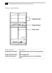
4 VAIO Digital Studio System Reference Manual Buttons and Switches Optical disc eject Floppy disk eject Power on/off Button or switch Optical disc eject button Floppy disk eject button Power on , off switch Description Automatically opens and closes the optical drive tray. Turns system power on /off , or into Stand by mode. Ejects a floppy disk.
4 VAIO Digital Studio System Reference Manual Buttons and Switches Optical disc eject Floppy disk eject Power on/off Button or switch Optical disc eject button Floppy disk eject button Power on , off switch Description Automatically opens and closes the optical drive tray. Turns system power on /off , or into Stand by mode. Ejects a floppy disk.

System Reference Manual
Page 19
Light is red when the computer is on. Light is amber while reading and writing data from and to the optical drives. Light is green while reading and writing data from and to a floppy disk. Light is blue while the power is placed in Standby mode. Indicators Identifying ...Components 5 Floppy disk drive access Power Standby Optical disc drive access Hard disk drive access Indicator Floppy disk drive access indicator...
Light is red when the computer is on. Light is amber while reading and writing data from and to the optical drives. Light is green while reading and writing data from and to a floppy disk. Light is blue while the power is placed in Standby mode. Indicators Identifying ...Components 5 Floppy disk drive access Power Standby Optical disc drive access Hard disk drive access Indicator Floppy disk drive access indicator...
System Reference Manual
Page 20
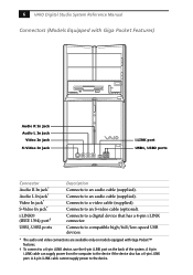
6 VAIO Digital Studio System Reference Manual Connectors (Models Equipped with Giga Pocket™ features. † ...; (IEEE 1394) port† USB1, USB2 ports Description Connects to an audio cable (supplied). A 4-pin i.LINK cable cannot supply power to a digital device that has a 4-pin i.LINK connector. Connects to the device. Connects to the device if the device also has... only on the back of the system. A 6-pin i.LINK cable can supply power from the computer to an audio cable (supplied). Connects to an S-video cable (optional). Connects to a video cable (supplied).
6 VAIO Digital Studio System Reference Manual Connectors (Models Equipped with Giga Pocket™ features. † ...; (IEEE 1394) port† USB1, USB2 ports Description Connects to an audio cable (supplied). A 4-pin i.LINK cable cannot supply power to a digital device that has a 4-pin i.LINK connector. Connects to the device. Connects to the device if the device also has... only on the back of the system. A 6-pin i.LINK cable can supply power from the computer to an audio cable (supplied). Connects to an S-video cable (optional). Connects to a video cable (supplied).

System Reference Manual
Page 27
The 4-pin i.LINK port at the bottom of the front panel does not supply power to designate that came with each other. The 6-pin port supplies 10 V to 12 V and a maximum power of 6 watts. ✍ i.LINK is a trademark of Sony used only to an i.LINK device. 6-pin i.LINK port (IEEE 1394) 4-pin i.LINK port... required operating conditions. Identifying Components 13 i.LINK S400 (IEEE 1394) Ports The 6-pin i.LINK® port on the back panel of the system can supply power from the computer to your compatible i.LINK device for the supplied speaker...
The 4-pin i.LINK port at the bottom of the front panel does not supply power to designate that came with each other. The 6-pin port supplies 10 V to 12 V and a maximum power of 6 watts. ✍ i.LINK is a trademark of Sony used only to an i.LINK device. 6-pin i.LINK port (IEEE 1394) 4-pin i.LINK port... required operating conditions. Identifying Components 13 i.LINK S400 (IEEE 1394) Ports The 6-pin i.LINK® port on the back panel of the system can supply power from the computer to your compatible i.LINK device for the supplied speaker...

