Quick Start Guide
Page 12
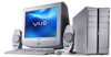
... configuration you purchased. Computer and supplied accessories System unit (PCV-RZ series model shown) Speakers* (PCVA-SP3A) with Speaker power cable Speakers* (PCVA-SP4) with your Computer Your computer may vary, depending on supplied accessories. 12 See the online specifications sheet for details on the VAIO computer model purchased. VAIO Digital Studio Computer Quick Start Unpacking your computer, see the...
... configuration you purchased. Computer and supplied accessories System unit (PCV-RZ series model shown) Speakers* (PCVA-SP3A) with Speaker power cable Speakers* (PCVA-SP4) with your Computer Your computer may vary, depending on supplied accessories. 12 See the online specifications sheet for details on the VAIO computer model purchased. VAIO Digital Studio Computer Quick Start Unpacking your computer, see the...
Quick Start Guide
Page 16
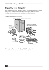
... Start About the Front Panel (PCV-RZ series model) The front panel of your VAIO Computer enables access to connect compatible peripheral devices. On certain models, the front panel also provides access to Giga Pocket Personal Video Recorder jacks and ... Stick media slot and the Universal Serial Bus (USB), and i.LINK® ports that enable you to the optical and floppy disk drives. Front panel (PCV-RZ series model) 1 Optical drive 1 See the online specifications sheet for optical drive information. 2 Optical drive 2 See the online specifications sheet for optical drive information...
... Start About the Front Panel (PCV-RZ series model) The front panel of your VAIO Computer enables access to connect compatible peripheral devices. On certain models, the front panel also provides access to Giga Pocket Personal Video Recorder jacks and ... Stick media slot and the Universal Serial Bus (USB), and i.LINK® ports that enable you to the optical and floppy disk drives. Front panel (PCV-RZ series model) 1 Optical drive 1 See the online specifications sheet for optical drive information. 2 Optical drive 2 See the online specifications sheet for optical drive information...

Quick Start Guide
Page 17
... Front Panel (PCV-RZ series model) 4 Floppy disk drive access indicator Light is green while reading and writing data from and to a floppy disk. 5 Power indicator Light is blue while the power is on. 6 Power switch Turns the computer on and off. 7 Stand by indicator Light is red when the computer is placed in...
... Front Panel (PCV-RZ series model) 4 Floppy disk drive access indicator Light is green while reading and writing data from and to a floppy disk. 5 Power indicator Light is blue while the power is on. 6 Power switch Turns the computer on and off. 7 Stand by indicator Light is red when the computer is placed in...
Quick Start Guide
Page 19
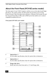
... model) MONITOR USB MIC HEADPHONES LINE IN MONITOR AUDIO S VIDEO/VIDEO AUDIO S VIDEO/VIDEO - About the Back Panel (PCV-RZ series model) About the Back Panel (PCV-RZ series model) The back panel of your computer. VHF/UHF PHONE LINE 1 AC Input port Connection for the supplied power cord. 2 Mouse port Connection for a PS/2®...
... model) MONITOR USB MIC HEADPHONES LINE IN MONITOR AUDIO S VIDEO/VIDEO AUDIO S VIDEO/VIDEO - About the Back Panel (PCV-RZ series model) About the Back Panel (PCV-RZ series model) The back panel of your computer. VHF/UHF PHONE LINE 1 AC Input port Connection for the supplied power cord. 2 Mouse port Connection for a PS/2®...

Quick Start Guide
Page 21
... jack Connection for the modem (supplied) cable to the wall jack. * This monitor port may vary, depending on supplied accessories. 21 About the Back Panel (PCV-RZ series model) 16 (For models equipped with your computer may have a cover, indicating that it is not available for use.
... jack Connection for the modem (supplied) cable to the wall jack. * This monitor port may vary, depending on supplied accessories. 21 About the Back Panel (PCV-RZ series model) 16 (For models equipped with your computer may have a cover, indicating that it is not available for use.
Quick Start Guide
Page 32
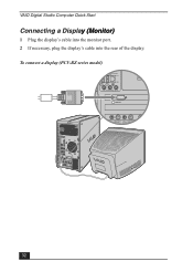
VAIO Digital Studio Computer Quick Start Connecting a Display (Monitor) 1 Plug the display's cable into the monitor port. 2 If necessary, plug the display's cable into the rear of the display. To connect a display (PCV-RZ series model) 32
VAIO Digital Studio Computer Quick Start Connecting a Display (Monitor) 1 Plug the display's cable into the monitor port. 2 If necessary, plug the display's cable into the rear of the display. To connect a display (PCV-RZ series model) 32

Quick Start Guide
Page 33
Connecting a Display (Monitor) To connect a DVI display (PCV-RZ series model) ✍ Install your equipment so that you can easily reach the power outlet in the event of an emergency. 33
Connecting a Display (Monitor) To connect a DVI display (PCV-RZ series model) ✍ Install your equipment so that you can easily reach the power outlet in the event of an emergency. 33
Quick Start Guide
Page 34
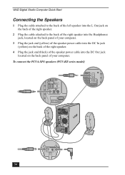
VAIO Digital Studio Computer Quick Start Connecting the Speakers 1 Plug the cable attached to the back of the left speaker into the L Out jack on ...the right speaker. 2 Plug the cable attached to the back of the right speaker into the Headphones jack, located on the back panel of your computer. 3 Plug the jack end (yellow) of the speaker power cable into the DC In jack (yellow) on the back of the right speaker... 4 Plug the jack end (black) of the speaker power cable into the DC Out jack located on the back panel of your computer. To connect the PCVA-SP4 speakers (PCV-RZ series model) USB 4 34
VAIO Digital Studio Computer Quick Start Connecting the Speakers 1 Plug the cable attached to the back of the left speaker into the L Out jack on ...the right speaker. 2 Plug the cable attached to the back of the right speaker into the Headphones jack, located on the back panel of your computer. 3 Plug the jack end (yellow) of the speaker power cable into the DC In jack (yellow) on the back of the right speaker... 4 Plug the jack end (black) of the speaker power cable into the DC Out jack located on the back panel of your computer. To connect the PCVA-SP4 speakers (PCV-RZ series model) USB 4 34
Quick Start Guide
Page 36
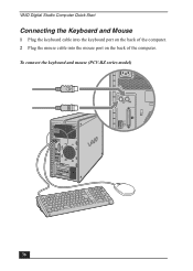
VAIO Digital Studio Computer Quick Start Connecting the Keyboard and Mouse 1 Plug the keyboard cable into the keyboard port on the back of the computer. 2 Plug the mouse cable into the mouse port on the back of the computer. To connect the keyboard and mouse (PCV-RZ series model) KEYBOARD MOUSE PRINTER i.LINK S400 OPTICAL 36
VAIO Digital Studio Computer Quick Start Connecting the Keyboard and Mouse 1 Plug the keyboard cable into the keyboard port on the back of the computer. 2 Plug the mouse cable into the mouse port on the back of the computer. To connect the keyboard and mouse (PCV-RZ series model) KEYBOARD MOUSE PRINTER i.LINK S400 OPTICAL 36

Quick Start Guide
Page 37
Using other end of the cable into the modem line jack, located on the back panel of your computer. 2 Plug the modem cable (supplied) into the wall jack. Connect only 10BASE-T and 100BASE-TX cables to a network, see your network administrator. 37 For help ... located on the back panel of your computer 3 Plug the other cables or a telephone cable may result in an electric current overload that can cause a malfunction, excessive heat, or fire in the Ethernet port. To connect the telephone and modem cables (PCV-RZ series model) Your computer has a protective sticker covering the Ethernet port...
Using other end of the cable into the modem line jack, located on the back panel of your computer. 2 Plug the modem cable (supplied) into the wall jack. Connect only 10BASE-T and 100BASE-TX cables to a network, see your network administrator. 37 For help ... located on the back panel of your computer 3 Plug the other cables or a telephone cable may result in an electric current overload that can cause a malfunction, excessive heat, or fire in the Ethernet port. To connect the telephone and modem cables (PCV-RZ series model) Your computer has a protective sticker covering the Ethernet port...
Quick Start Guide
Page 38
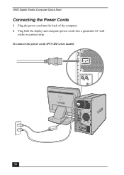
To connect the power cords (PCV-RZ series model) KEYBOARD MOUSE PRINTER 38 VAIO Digital Studio Computer Quick Start Connecting the Power Cords 1 Plug the power cord into the back of the computer. 2 Plug both the display and computer power cords into a grounded AC wall outlet or a power strip.
To connect the power cords (PCV-RZ series model) KEYBOARD MOUSE PRINTER 38 VAIO Digital Studio Computer Quick Start Connecting the Power Cords 1 Plug the power cord into the back of the computer. 2 Plug both the display and computer power cords into a grounded AC wall outlet or a power strip.

Quick Start Guide
Page 39
Respond to this prompt immediately. 1 Press the power button on the computer to turn on the power. 2 Press the power button on the display to turn on the power. 3 Press the power button on the right speaker to restart your computer (PCV-RZ series model with PCVA-SP4 speakers) To turn on the power. Turning On your Computer Turning On your Computer When you start your system for the first time, your computer may detect new equipment and display a dialog box that prompts you to turn on your computer (PCV-RX series model with PCVA-SP3A speakers shown) 39 To turn on your computer.
Respond to this prompt immediately. 1 Press the power button on the computer to turn on the power. 2 Press the power button on the display to turn on the power. 3 Press the power button on the right speaker to restart your computer (PCV-RZ series model with PCVA-SP4 speakers) To turn on the power. Turning On your Computer Turning On your Computer When you start your system for the first time, your computer may detect new equipment and display a dialog box that prompts you to turn on your computer (PCV-RX series model with PCVA-SP3A speakers shown) 39 To turn on your computer.
Quick Start Guide
Page 51
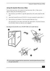
... drive 1. 3 Press the disc eject button to close the optical disk drive tray. Inserting the System Recovery CD (PCV-RZ series model shown) ✍ If your computer. A blue screen appears during the downloading process. 1 Press the disc eject button to load necessary files. The System Recovery utility starts from the optical drive. ...
... drive 1. 3 Press the disc eject button to close the optical disk drive tray. Inserting the System Recovery CD (PCV-RZ series model shown) ✍ If your computer. A blue screen appears during the downloading process. 1 Press the disc eject button to load necessary files. The System Recovery utility starts from the optical drive. ...
System Reference Manual
Page 11
Configuring Your System 15 Accessing the BIOS Setup Utility 16 Changing Power Management Settings 17 xi Identifying Components 1 Front View (PCV-RZ Series model 2 Drives ...3 Buttons and Switches 4 Indicators 5 Connectors (Models Equipped with Giga Pocket Features)..........6 Rear View (Model Equipped with Giga Pocket Features 7 Icon Labels 8 I/O Connectors ...
Configuring Your System 15 Accessing the BIOS Setup Utility 16 Changing Power Management Settings 17 xi Identifying Components 1 Front View (PCV-RZ Series model 2 Drives ...3 Buttons and Switches 4 Indicators 5 Connectors (Models Equipped with Giga Pocket Features)..........6 Rear View (Model Equipped with Giga Pocket Features 7 Icon Labels 8 I/O Connectors ...
System Reference Manual
Page 12
...Removing the Side Panel 24 To remove the side panel (PCV-RZ series model 24 To remove the side panel (PCV-RX series model 25 Replacing the Side Panel 26 To replace the side panel (PCV-RZ series model 26 To replace the side panel (PCV-RX series model 27 Installing an Add-on Card 28...Open I/O Slot 43 Installing an Additional Hard Disk Drive 44 To identify additional hard disk space 48 Removing the Power Supply (PCV-RX series models 49 Replacing the Power Supply (PCV-RX series model 50 Chapter 4 - CMOS Setup Options 57 Main Screen 59 Advanced Screen 61 Power Screen 63 Boot Screen ...
...Removing the Side Panel 24 To remove the side panel (PCV-RZ series model 24 To remove the side panel (PCV-RX series model 25 Replacing the Side Panel 26 To replace the side panel (PCV-RZ series model 26 To replace the side panel (PCV-RX series model 27 Installing an Add-on Card 28...Open I/O Slot 43 Installing an Additional Hard Disk Drive 44 To identify additional hard disk space 48 Removing the Power Supply (PCV-RX series models 49 Replacing the Power Supply (PCV-RX series model 50 Chapter 4 - CMOS Setup Options 57 Main Screen 59 Advanced Screen 61 Power Screen 63 Boot Screen ...
System Reference Manual
Page 38
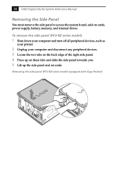
Removing the side panel (PCV-RZ series model equipped with Giga Pocket) 24 VAIO Digital Studio System Reference Manual Removing the Side Panel You must remove the side panel to access the system board, add-on these tabs and .... 5 Lift up on cards, power supply, battery, memory, and internal drives. To remove the side panel (PCV-RZ series model) 1 Shut down your computer and turn off all peripheral devices, such as your printer. 2 Unplug your computer and disconnect any peripheral devices. 3 Locate the two tabs on the back edge of the right side...
Removing the side panel (PCV-RZ series model equipped with Giga Pocket) 24 VAIO Digital Studio System Reference Manual Removing the Side Panel You must remove the side panel to access the system board, add-on these tabs and .... 5 Lift up on cards, power supply, battery, memory, and internal drives. To remove the side panel (PCV-RZ series model) 1 Shut down your computer and turn off all peripheral devices, such as your printer. 2 Unplug your computer and disconnect any peripheral devices. 3 Locate the two tabs on the back edge of the right side...
System Reference Manual
Page 40
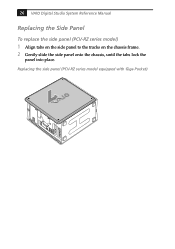
26 VAIO Digital Studio System Reference Manual Replacing the Side Panel To replace the side panel (PCV-RZ series model) 1 Align tabs on the side panel to the tracks on the chassis frame. 2 Gently slide the side panel onto the chassis, until the tabs lock the panel into place. Replacing the side panel (PCV-RZ series model equipped with Giga Pocket)
26 VAIO Digital Studio System Reference Manual Replacing the Side Panel To replace the side panel (PCV-RZ series model) 1 Align tabs on the side panel to the tracks on the chassis frame. 2 Gently slide the side panel onto the chassis, until the tabs lock the panel into place. Replacing the side panel (PCV-RZ series model equipped with Giga Pocket)
System Reference Manual
Page 51
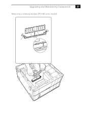
Upgrading and Maintaining Components 37 Removing a memory module (PCV-RZ series model)
Upgrading and Maintaining Components 37 Removing a memory module (PCV-RZ series model)
PCV-RZ Series Hard Disk Drive Replacement Instructions
Page 1
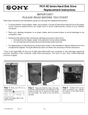
...sure product is turned off and disconnected from the power source. This slight difference does not affect the accuracy of these instructions. * Sony is facing to guide you . Press and hold the 2 tabs in the illustrations may be exposed. o Do not walk around ... desktop computer on a clean, stable and covered surface to avoid damage to the computer's case.* 9 Follow the ESD (Electrostatic Discharge) damage prevention instructions: o Hold parts by incorrect handling of your PC on the right as shown. Slide the panel in unit damage or personal injury. B 1/2 PCV-RZ ...
...sure product is turned off and disconnected from the power source. This slight difference does not affect the accuracy of these instructions. * Sony is facing to guide you . Press and hold the 2 tabs in the illustrations may be exposed. o Do not walk around ... desktop computer on a clean, stable and covered surface to avoid damage to the computer's case.* 9 Follow the ESD (Electrostatic Discharge) damage prevention instructions: o Hold parts by incorrect handling of your PC on the right as shown. Slide the panel in unit damage or personal injury. B 1/2 PCV-RZ ...
PCV-RZ Series Hard Disk Drive Replacement Instructions
Page 2
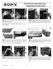
... the direction of each side) are locked in place. 2 Step 9. P/N T99860132 Rev. IMPORTANT! IMPORTANT! Reconnect the IDE Cable [1] and Power Cable [2] into the bracket. 1 Step 8. B 2/2 PCV-RZ Series Hard Disk Drive Replacement Instructions 1 [A] [B] 2 Step 4. Using the enclosed magnetic screwdriver, remove the four (4) screws that all holes in alignment Step 6. Reinstall the rail...
... the direction of each side) are locked in place. 2 Step 9. P/N T99860132 Rev. IMPORTANT! IMPORTANT! Reconnect the IDE Cable [1] and Power Cable [2] into the bracket. 1 Step 8. B 2/2 PCV-RZ Series Hard Disk Drive Replacement Instructions 1 [A] [B] 2 Step 4. Using the enclosed magnetic screwdriver, remove the four (4) screws that all holes in alignment Step 6. Reinstall the rail...


