
System Reference Manual
Page 2
...PCV-RX462DS/ PCV-RX463DS/PCV-RX465DS/ PCV-RX470DS/PCV-RX480DS/ PCV-RX490TV Serial Number ii Sony Electronics Inc. reserves the right to make any modification to software may require a fee and credit card information. Updates and additions to this product. Subscriptions to the terms and conditions of IBM Corporation. Sony, VAIO, the VAIO logo, VAIO Digital Studio... when you call your VAIO® computer. BE LIABLE FOR ANY INCIDENTAL, CONSEQUENTIAL, OR SPECIAL DAMAGES, WHETHER BASED ON TORT, CONTRACT, OR OTHERWISE, ARISING OUT OF OR IN CONNECTION WITH THIS MANUAL, THE SOFTWARE, OR ...
...PCV-RX462DS/ PCV-RX463DS/PCV-RX465DS/ PCV-RX470DS/PCV-RX480DS/ PCV-RX490TV Serial Number ii Sony Electronics Inc. reserves the right to make any modification to software may require a fee and credit card information. Updates and additions to this product. Subscriptions to the terms and conditions of IBM Corporation. Sony, VAIO, the VAIO logo, VAIO Digital Studio... when you call your VAIO® computer. BE LIABLE FOR ANY INCIDENTAL, CONSEQUENTIAL, OR SPECIAL DAMAGES, WHETHER BASED ON TORT, CONTRACT, OR OTHERWISE, ARISING OUT OF OR IN CONNECTION WITH THIS MANUAL, THE SOFTWARE, OR ...
System Reference Manual
Page 6
...uses the USOC RJ-11 telephone jack. But if advance notice is likely to result in interference to radio and television reception. If this manual could affect the operations of service may be required. Operation with cables, connected to peripherals, that are cautioned that any changes or modifications ...line. In most, but not all areas, the sum of the FCC rules. The telephone company may be connected to the line, as computer input/ output devices, terminals, and printers) that comply with the FCC if you in advance that temporary discontinuance of the equipment. If requested, this...
...uses the USOC RJ-11 telephone jack. But if advance notice is likely to result in interference to radio and television reception. If this manual could affect the operations of service may be required. Operation with cables, connected to peripherals, that are cautioned that any changes or modifications ...line. In most, but not all areas, the sum of the FCC rules. The telephone company may be connected to the line, as computer input/ output devices, terminals, and printers) that comply with the FCC if you in advance that temporary discontinuance of the equipment. If requested, this...

System Reference Manual
Page 12
...Port 70 Headphones, Line In, Mic Jacks 71 i.LINK Headers 72 CD-IN Header 73 AUX-IN Header 74 Video Header 75 xii VAIO Digital Studio™ System Reference Manual Chapter 3 - Removing, Installing, and Replacing Components 27 Removing the Side Cover 28 Replacing the Side Cover 29 Installing a PCI Add-In... Module 41 Removing a Slot Cover 43 Covering an Open I/O Slot 44 Installing a 3.5-inch Internal Hard Disk Drive 45 To prepare a startup disk (PCV-RX490TV model only 45 To install a 3.5-inch internal hard disk drive (all models 46 To set up the new hard drive with the startup disk...
...Port 70 Headphones, Line In, Mic Jacks 71 i.LINK Headers 72 CD-IN Header 73 AUX-IN Header 74 Video Header 75 xii VAIO Digital Studio™ System Reference Manual Chapter 3 - Removing, Installing, and Replacing Components 27 Removing the Side Cover 28 Replacing the Side Cover 29 Installing a PCI Add-In... Module 41 Removing a Slot Cover 43 Covering an Open I/O Slot 44 Installing a 3.5-inch Internal Hard Disk Drive 45 To prepare a startup disk (PCV-RX490TV model only 45 To install a 3.5-inch internal hard disk drive (all models 46 To set up the new hard drive with the startup disk...

System Reference Manual
Page 14
xiv VAIO Digital Studio™ System Reference Manual Audio ...111 Communications 112 Giga Pocket I/O (PCV-RX490TV only 112 I/O and Expansion Slots 112 Floppy Disk Drive and Controller 113 Hard Drives and Controllers 113 Optical Drives 114 System BIOS 116 Index 117
xiv VAIO Digital Studio™ System Reference Manual Audio ...111 Communications 112 Giga Pocket I/O (PCV-RX490TV only 112 I/O and Expansion Slots 112 Floppy Disk Drive and Controller 113 Hard Drives and Controllers 113 Optical Drives 114 System BIOS 116 Index 117
System Reference Manual
Page 15
Chapter 1 Identifying Components The following sections identify and describe each component that is visible from the exterior of this manual. 1 Internal components are identified in the appropriate section of the VAIO Digital Studio™ computer.
Chapter 1 Identifying Components The following sections identify and describe each component that is visible from the exterior of this manual. 1 Internal components are identified in the appropriate section of the VAIO Digital Studio™ computer.

System Reference Manual
Page 16
2 VAIO Digital Studio™ System Reference Manual Front View All Models
2 VAIO Digital Studio™ System Reference Manual Front View All Models

System Reference Manual
Page 18
... on a CD-R/CD-RW is written at the outermost track. The CD-RW/CD-R/CD-ROM data transfer standard rate is 22.5X (3375 KBps). PCV-RX490TV DVD-RW drive CD-ROM drive Floppy disk drive Drive Floppy disk drive DVD-RW drive* DVD-ROM read† DVD-RW/DVD-R read‡...-R read at a variable transfer rate, ranging from 13X at the innermost track to 32X at a constant transfer rate of 2X, 4X, 8X (max. 4 VAIO Digital Studio™ System Reference Manual ***Data on a CD-R/CD-ROM is read †† CD-R write CD-RW write‡‡ DVD-R write*** DVD-RW write CD-ROM drive...
... on a CD-R/CD-RW is written at the outermost track. The CD-RW/CD-R/CD-ROM data transfer standard rate is 22.5X (3375 KBps). PCV-RX490TV DVD-RW drive CD-ROM drive Floppy disk drive Drive Floppy disk drive DVD-RW drive* DVD-ROM read† DVD-RW/DVD-R read‡...-R read at a variable transfer rate, ranging from 13X at the innermost track to 32X at a constant transfer rate of 2X, 4X, 8X (max. 4 VAIO Digital Studio™ System Reference Manual ***Data on a CD-R/CD-ROM is read †† CD-R write CD-RW write‡‡ DVD-R write*** DVD-RW write CD-ROM drive...
System Reference Manual
Page 20
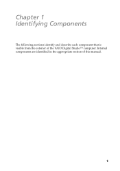
Automatically opens and closes the optical drive tray. 6 VAIO Digital Studio™ System Reference Manual Buttons and Switches All Models Optical disc eject Floppy disk eject Power/Stand by Button or switch Power/Stand by switch Floppy disk eject button Optical disc eject button Description Turns system power on, off, or into Stand by mode. Ejects a floppy disk.
Automatically opens and closes the optical drive tray. 6 VAIO Digital Studio™ System Reference Manual Buttons and Switches All Models Optical disc eject Floppy disk eject Power/Stand by Button or switch Power/Stand by switch Floppy disk eject button Optical disc eject button Description Turns system power on, off, or into Stand by mode. Ejects a floppy disk.

System Reference Manual
Page 22
Connects to USB devices. * To connect to the device. A 4-pin i.LINK header cannot supply power to a 6-pin i.LINK device, use the i.LINK header on the back of the system. 8 VAIO Digital Studio™ System Reference Manual Connectors PCV-RX462DS/PCV-RX463DS/PCV-RX465DS/PCV-RX470DS/PCV-RX480DS USB3, USB4 i.LINK Connector i.LINK® (IEEE1394)* USB3, USB4 Description Connects to the device if the device also has a 6-pin i.LINK header. A 6-pin i.LINK header can supply power from the computer to a digital device that has a 4-pin i.LINK header.
Connects to USB devices. * To connect to the device. A 4-pin i.LINK header cannot supply power to a 6-pin i.LINK device, use the i.LINK header on the back of the system. 8 VAIO Digital Studio™ System Reference Manual Connectors PCV-RX462DS/PCV-RX463DS/PCV-RX465DS/PCV-RX470DS/PCV-RX480DS USB3, USB4 i.LINK Connector i.LINK® (IEEE1394)* USB3, USB4 Description Connects to the device if the device also has a 6-pin i.LINK header. A 6-pin i.LINK header can supply power from the computer to a digital device that has a 4-pin i.LINK header.

System Reference Manual
Page 24
10 VAIO Digital Studio™ System Reference Manual Rear View All Models Mouse Keyboard USB1, USB2 Ethernet Serial Printer /Parallel i.LINK (IEEE394) Game/MIDI Headphones Line In Microphone Monitor Audio Out Video/S-video Out* Audio In Video/S-Video In* Line Power DVI VHF/UHF* Telephone** *Only in PCV-RX490TV Model ** In models with an HPNA modem, the telephone line jack does not exist.
10 VAIO Digital Studio™ System Reference Manual Rear View All Models Mouse Keyboard USB1, USB2 Ethernet Serial Printer /Parallel i.LINK (IEEE394) Game/MIDI Headphones Line In Microphone Monitor Audio Out Video/S-video Out* Audio In Video/S-Video In* Line Power DVI VHF/UHF* Telephone** *Only in PCV-RX490TV Model ** In models with an HPNA modem, the telephone line jack does not exist.

System Reference Manual
Page 26
PCV-RX490TV Only Icon Description VHF/UHF port Audio In jack Audio Out jack Video/S-video In port Video/S-video Out port 12 VAIO Digital Studio™ System Reference Manual All Models Icon Description Headphones LINE IN jack (audio) Microphone jack Monitor port Line jack (for telephone line from primary service jack) Telephone jack (for phone)* DVI (LCD) Monitor port * In models with an HPNA modem, the telephone jack does not exist.
PCV-RX490TV Only Icon Description VHF/UHF port Audio In jack Audio Out jack Video/S-video In port Video/S-video Out port 12 VAIO Digital Studio™ System Reference Manual All Models Icon Description Headphones LINE IN jack (audio) Microphone jack Monitor port Line jack (for telephone line from primary service jack) Telephone jack (for phone)* DVI (LCD) Monitor port * In models with an HPNA modem, the telephone jack does not exist.
System Reference Manual
Page 28
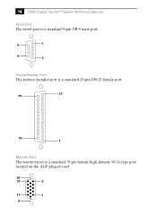
14 VAIO Digital Studio™ System Reference Manual Serial Port The serial port is a standard 9-pin DB-9 male port. 6 1 9 5 Printer/Parallel Port The printer/parallel port is a standard 25-pin DB-25 female port. 13 25 14 1 Monitor Port The monitor port is a standard 15-pin female high-density VGA-type port located on the AGP plug-in card. 10 15 5 11 1 6
14 VAIO Digital Studio™ System Reference Manual Serial Port The serial port is a standard 9-pin DB-9 male port. 6 1 9 5 Printer/Parallel Port The printer/parallel port is a standard 25-pin DB-25 female port. 13 25 14 1 Monitor Port The monitor port is a standard 15-pin female high-density VGA-type port located on the AGP plug-in card. 10 15 5 11 1 6
System Reference Manual
Page 30
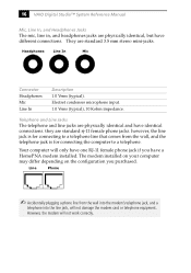
16 VAIO Digital Studio™ System Reference Manual Mic, Line In, and Headphones Jacks The mic, line in, and headphones jacks are physically identical, but have identical connections. Electret condenser microphone input. 1.0 Vrms (typical), 10 Kohm impedance. Your computer will only have a HomePNA modem installed. However, ...Headphones Mic Line In Description 1.0 Vrms (typical). they are standard 3.5 mm stereo mini-jacks. The modem installed on your computer may differ depending on the configuration you have one RJ-11 female phone jack if you purchased. Telephone and Line Jacks The ...
16 VAIO Digital Studio™ System Reference Manual Mic, Line In, and Headphones Jacks The mic, line in, and headphones jacks are physically identical, but have identical connections. Electret condenser microphone input. 1.0 Vrms (typical), 10 Kohm impedance. Your computer will only have a HomePNA modem installed. However, ...Headphones Mic Line In Description 1.0 Vrms (typical). they are standard 3.5 mm stereo mini-jacks. The modem installed on your computer may differ depending on the configuration you have one RJ-11 female phone jack if you purchased. Telephone and Line Jacks The ...
System Reference Manual
Page 32
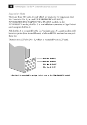
... an HPNA modem has one AGP slot (No. 4), which are available for expansion; In the PCV-RX490TV model, slot No. 3 is occupied by the fax/modem card. There is one jack (Line In). 18 VAIO Digital Studio™ System Reference Manual Expansion Slots There are three PCI slots, two of which is occupied by an AGP...
... an HPNA modem has one AGP slot (No. 4), which are available for expansion; In the PCV-RX490TV model, slot No. 3 is occupied by the fax/modem card. There is one jack (Line In). 18 VAIO Digital Studio™ System Reference Manual Expansion Slots There are three PCI slots, two of which is occupied by an AGP...

System Reference Manual
Page 36
...the menu bar. The following message appears at the bottom of options from the Start menu, then selecting Restart. 2 When the Sony logo appears, press F3. Each menu presents options for setup. 3 Press F2. Use the left and right arrow keys to its...VAIO Digital Studio™ System Reference Manual Accessing the BIOS Setup Utility You must access the BIOS Setup Utility to make changes to the BIOS settings (see "CMOS Setup Options" on page 85 for information on BIOS settings). ! Before rebooting the system, save and close all open files, and exit open applications. 1 Reboot your computer...
...the menu bar. The following message appears at the bottom of options from the Start menu, then selecting Restart. 2 When the Sony logo appears, press F3. Each menu presents options for setup. 3 Press F2. Use the left and right arrow keys to its...VAIO Digital Studio™ System Reference Manual Accessing the BIOS Setup Utility You must access the BIOS Setup Utility to make changes to the BIOS settings (see "CMOS Setup Options" on page 85 for information on BIOS settings). ! Before rebooting the system, save and close all open files, and exit open applications. 1 Reboot your computer...
System Reference Manual
Page 38
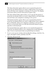
...when you want to elapse before your computer goes on Stand by option allows you to specify the period of inactivity (in minutes) that you click the left mouse button or press spacebar on AC power. 24 VAIO Digital Studio™ System Reference Manual The Turn off monitor option allows ...you to specify the period of inactivity (in minutes) that you want to specify the period of inactivity (in minutes) before your computer goes in the hibernate state. The Turn...
...when you want to elapse before your computer goes on Stand by option allows you to specify the period of inactivity (in minutes) that you click the left mouse button or press spacebar on AC power. 24 VAIO Digital Studio™ System Reference Manual The Turn off monitor option allows ...you to specify the period of inactivity (in minutes) that you want to specify the period of inactivity (in minutes) before your computer goes in the hibernate state. The Turn...
System Reference Manual
Page 42
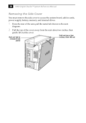
Pull out tab to access the system board, add-in cards, power supply, battery, memory, and internal drives. 1 From the rear of the unit, pull the metal tab shown in the next diagram. 2 Pull the top of the cover away from the unit about two inches, then gently lift out the cover. 28 VAIO Digital Studio™ System Reference Manual Removing the Side Cover You must remove the side cover to release front panel Pull out top a few inches, then lift out
Pull out tab to access the system board, add-in cards, power supply, battery, memory, and internal drives. 1 From the rear of the unit, pull the metal tab shown in the next diagram. 2 Pull the top of the cover away from the unit about two inches, then gently lift out the cover. 28 VAIO Digital Studio™ System Reference Manual Removing the Side Cover You must remove the side cover to release front panel Pull out top a few inches, then lift out
System Reference Manual
Page 44
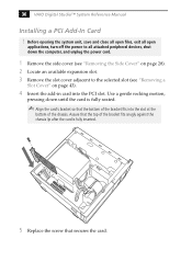
... fits snugly against the chassis lip after the card is fully seated. ✍ Align the card's bracket so that secures the card. 30 VAIO Digital Studio™ System Reference Manual Installing a PCI Add-In Card ! Before opening the system unit, save and close all open files, exit all open applications, turn off... the add-in card into the slot at the bottom of the bracket fits into the PCI slot. Use a gentle rocking motion, pressing down the computer, and unplug the power cord. 1 Remove the side cover (see "Removing the Side Cover" on page 28). 2 Locate an available expansion slot. 3 ...
... fits snugly against the chassis lip after the card is fully seated. ✍ Align the card's bracket so that secures the card. 30 VAIO Digital Studio™ System Reference Manual Installing a PCI Add-In Card ! Before opening the system unit, save and close all open files, exit all open applications, turn off... the add-in card into the slot at the bottom of the bracket fits into the PCI slot. Use a gentle rocking motion, pressing down the computer, and unplug the power cord. 1 Remove the side cover (see "Removing the Side Cover" on page 28). 2 Locate an available expansion slot. 3 ...
System Reference Manual
Page 46
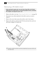
32 VAIO Digital Studio™ System Reference Manual Removing a PCI Add-in an anti-static wrapper for future use. ✍ Grasp the card with one hand on each end, and gently pull up ... the system unit, save and close all open files, exit all open applications, turn off the power to all attached peripheral devices, shut down the computer, and unplug the power cord. 1 Remove the side cover (see "Removing the Side Cover" on page 28). 2 Disconnect any cables attached to the add-in...
32 VAIO Digital Studio™ System Reference Manual Removing a PCI Add-in an anti-static wrapper for future use. ✍ Grasp the card with one hand on each end, and gently pull up ... the system unit, save and close all open files, exit all open applications, turn off the power to all attached peripheral devices, shut down the computer, and unplug the power cord. 1 Remove the side cover (see "Removing the Side Cover" on page 28). 2 Disconnect any cables attached to the add-in...
System Reference Manual
Page 48
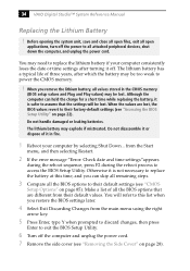
... at this list when you remove the lithium battery, all values stored in fire. 1 Reboot your computer consistently loses the date or time settings after which the battery may explode if mistreated. 34 VAIO Digital Studio™ System Reference Manual Replacing the Lithium Battery ! Otherwise it is not necessary to assume that are lost . Although...
... at this list when you remove the lithium battery, all values stored in fire. 1 Reboot your computer consistently loses the date or time settings after which the battery may explode if mistreated. 34 VAIO Digital Studio™ System Reference Manual Replacing the Lithium Battery ! Otherwise it is not necessary to assume that are lost . Although...


