
System Reference Manual
Page 12
... 57 AGP Slot 58 IDE Headers 59 Power Supply and Aux Power Headers 60 Keyboard and Mouse Ports 62 USB Ports and USB Header 63 Ethernet Port 65 Serial , Printer, and i.LINK Ports 65 Fan Headers 69 Game Port 70 Headphones, Line In, Mic Jacks 71 i.LINK Headers 72 ...all models 46 To set up the new hard drive with the startup disk (PCV-RX490TV model only 49 To identify the additional hard disk space for Giga Pocket use (PCV-RX490TV model only 49 Removing the Power Supply 50 Replacing the Power Supply 51 Chapter 4 - xii VAIO Digital Studio™ System Reference Manual Chapter 3 -
... 57 AGP Slot 58 IDE Headers 59 Power Supply and Aux Power Headers 60 Keyboard and Mouse Ports 62 USB Ports and USB Header 63 Ethernet Port 65 Serial , Printer, and i.LINK Ports 65 Fan Headers 69 Game Port 70 Headphones, Line In, Mic Jacks 71 i.LINK Headers 72 ...all models 46 To set up the new hard drive with the startup disk (PCV-RX490TV model only 49 To identify the additional hard disk space for Giga Pocket use (PCV-RX490TV model only 49 Removing the Power Supply 50 Replacing the Power Supply 51 Chapter 4 - xii VAIO Digital Studio™ System Reference Manual Chapter 3 -

System Reference Manual
Page 24
10 VAIO Digital Studio™ System Reference Manual Rear View All Models Mouse Keyboard USB1, USB2 Ethernet Serial Printer /Parallel i.LINK (IEEE394) Game/MIDI Headphones Line In Microphone Monitor Audio Out Video/S-video Out* Audio In Video/S-Video In* Line Power DVI VHF/UHF* Telephone** *Only in PCV-RX490TV Model ** In models with an HPNA modem, the telephone line jack does not exist.
10 VAIO Digital Studio™ System Reference Manual Rear View All Models Mouse Keyboard USB1, USB2 Ethernet Serial Printer /Parallel i.LINK (IEEE394) Game/MIDI Headphones Line In Microphone Monitor Audio Out Video/S-video Out* Audio In Video/S-Video In* Line Power DVI VHF/UHF* Telephone** *Only in PCV-RX490TV Model ** In models with an HPNA modem, the telephone line jack does not exist.

System Reference Manual
Page 25
Icons All Models Identifying Components 11 Icon Label Area All Models Icon Description Mouse port Keyboard port Universal Serial Bus (USB) port Ethernet port (for LAN connection only) Serial port Printer port i.LINK (IEEE1394) port Game/MIDI port
Icons All Models Identifying Components 11 Icon Label Area All Models Icon Description Mouse port Keyboard port Universal Serial Bus (USB) port Ethernet port (for LAN connection only) Serial port Printer port i.LINK (IEEE1394) port Game/MIDI port

System Reference Manual
Page 27
Ethernet Port The Ethernet port at the rear of the system is used to connect to a 10Base-T/100Base-TX Ethernet network. Ethernet They are standard 6-pin PS/2®-type female ports. 2 3 1 4 6 5 USB Ports The USB ports are physically identical and have the same pinout. Two USB ports are located at the front, and two at the rear of the system. Keyboard and Mouse Ports The keyboard and mouse ports are standard 4-pin USB ports. Identifying Components 13 I/O Connectors The following section identifies the various I/O connectors.
Ethernet Port The Ethernet port at the rear of the system is used to connect to a 10Base-T/100Base-TX Ethernet network. Ethernet They are standard 6-pin PS/2®-type female ports. 2 3 1 4 6 5 USB Ports The USB ports are physically identical and have the same pinout. Two USB ports are located at the front, and two at the rear of the system. Keyboard and Mouse Ports The keyboard and mouse ports are standard 4-pin USB ports. Identifying Components 13 I/O Connectors The following section identifies the various I/O connectors.

System Reference Manual
Page 67
Keyboard, Mouse Processor Memory CPU Fan Power Supply Fan USB1, USB2, Ethernet Serial, Printer, iLink 1394 Header 2 Game, Mic In, Line In, Line Out 1394 Header 3 Aux-In Video Aux Power Supply Power Supply Secondary IDE Primary IDE Diskette Slot 4 (AGP) Battery CD-In Slot No. 3 (PCI) Slot No. 2 (PCI) Slot No. 1 (PCI) CMOS Clear Front Panel Header USB23 Header 53 Chapter 4 System Board This chapter identifies each component on the system board and provides a detailed description of each header, connector, and jumper on the system board.
Keyboard, Mouse Processor Memory CPU Fan Power Supply Fan USB1, USB2, Ethernet Serial, Printer, iLink 1394 Header 2 Game, Mic In, Line In, Line Out 1394 Header 3 Aux-In Video Aux Power Supply Power Supply Secondary IDE Primary IDE Diskette Slot 4 (AGP) Battery CD-In Slot No. 3 (PCI) Slot No. 2 (PCI) Slot No. 1 (PCI) CMOS Clear Front Panel Header USB23 Header 53 Chapter 4 System Board This chapter identifies each component on the system board and provides a detailed description of each header, connector, and jumper on the system board.

System Reference Manual
Page 79
The Serial port is a 6-pin standard IEEE1394 port. The i.LINK connector is a DB-9 male connector. Ethernet Ethernet port Pin Signal Name 1 Tx+ 2 Tx- 3 Rx+ 4 N/C 5 N/C 6 Rx- 7 N/C 8 N/C Serial , Printer, and i.LINK Ports The serial, printer, and i.LINK ports are mounted in a single bracket on the system board. The printer port is one Ethernet port at the rear panel, which permits connection to a 10Base-T/100Base-TX Ethernet network. System Board 65 Ethernet Port There is a DB-25 female port.
The Serial port is a 6-pin standard IEEE1394 port. The i.LINK connector is a DB-9 male connector. Ethernet Ethernet port Pin Signal Name 1 Tx+ 2 Tx- 3 Rx+ 4 N/C 5 N/C 6 Rx- 7 N/C 8 N/C Serial , Printer, and i.LINK Ports The serial, printer, and i.LINK ports are mounted in a single bracket on the system board. The printer port is one Ethernet port at the rear panel, which permits connection to a 10Base-T/100Base-TX Ethernet network. System Board 65 Ethernet Port There is a DB-25 female port.
System Reference Manual
Page 120
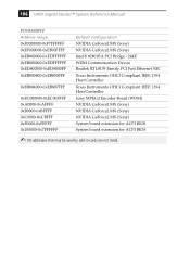
...VAIO Digital Studio™ System Reference Manual PCV-RX490TV Address range 0xF0000000-0xF7FFFFFF 0xEF000000-0xEF00FFFF 0xEB800000-0xEDFFFFFF 0xEB800000-0xEDFFFFFF 0xED800000-0xED8000FF 0xEB800800-0xEB800FFF 0xEB804000-0xEB807FFF 0xEC000000-0xEC00FFFF 0xA0000-0xAFFFF 0xB0000-0xBFFFF 0xC0000-0xCBFFF 0xF0000-0xFFFFF 0x100000-0x7FFFFFF Default configuration NVIDIA GeForce2 MX (Sony) NVIDIA GeForce2 MX (Sony...) Intel® 82801BA PCI Bridge - 244E WDM Communication Device Realtek RTL8139 Family PCI Fast Ethernet NIC Texas Instruments OHCI...
...VAIO Digital Studio™ System Reference Manual PCV-RX490TV Address range 0xF0000000-0xF7FFFFFF 0xEF000000-0xEF00FFFF 0xEB800000-0xEDFFFFFF 0xEB800000-0xEDFFFFFF 0xED800000-0xED8000FF 0xEB800800-0xEB800FFF 0xEB804000-0xEB807FFF 0xEC000000-0xEC00FFFF 0xA0000-0xAFFFF 0xB0000-0xBFFFF 0xC0000-0xCBFFF 0xF0000-0xFFFFF 0x100000-0x7FFFFFF Default configuration NVIDIA GeForce2 MX (Sony) NVIDIA GeForce2 MX (Sony...) Intel® 82801BA PCI Bridge - 244E WDM Communication Device Realtek RTL8139 Family PCI Fast Ethernet NIC Texas Instruments OHCI...

System Reference Manual
Page 121
...PCV-RX462DS/PCV-RX463DS/PCV-RX465DS/PCV-RX470DS/PCV-RX480DS IRQ Description 0 System timer 1 Standard 101/102-Key or Microsoft Natural Keyboard 2 Programmable interrupt controller 3 ACPI IRQ Holder for PCI IRQ Steering 3 Intel® 82801BA/BAM SMBus Controller - 2443 3 SoundMAX Integrated Digital...IRQ Holder for PCI IRQ Steering 9 Realtek RTL8139(A/B/C/8130) PCI Fast Ethernet NIC 9 Texas Instruments OHCI Compliant IEEE 1394 Host Controller 9 WDM Communication... Holder for PCI IRQ Steering 11 NVIDIA GeForce2 MX (Sony) 12 PS/2 Compatible Mouse Port 13 Numeric data processor...
...PCV-RX462DS/PCV-RX463DS/PCV-RX465DS/PCV-RX470DS/PCV-RX480DS IRQ Description 0 System timer 1 Standard 101/102-Key or Microsoft Natural Keyboard 2 Programmable interrupt controller 3 ACPI IRQ Holder for PCI IRQ Steering 3 Intel® 82801BA/BAM SMBus Controller - 2443 3 SoundMAX Integrated Digital...IRQ Holder for PCI IRQ Steering 9 Realtek RTL8139(A/B/C/8130) PCI Fast Ethernet NIC 9 Texas Instruments OHCI Compliant IEEE 1394 Host Controller 9 WDM Communication... Holder for PCI IRQ Steering 11 NVIDIA GeForce2 MX (Sony) 12 PS/2 Compatible Mouse Port 13 Numeric data processor...

