
User Guide
Page 29
... accurate. ❑ Make sure the video head of your computer, turn off the computer when connecting a camera. You cannot add audio on the stereo 2 track after capturing the video data. ❑ You cannot use DVgate when the connected digital video device is properly cleaned. You should not use ....; Captures larger than 2 GB (9 minutes and 30 seconds) are planning to work with DVgate. ❑ Title data is saved in the flash memory of capture sessions, you wish to create a panoramic picture. Using DVgate™ When capturing clips ❑ Do not use different audio modes on ...
... accurate. ❑ Make sure the video head of your computer, turn off the computer when connecting a camera. You cannot add audio on the stereo 2 track after capturing the video data. ❑ You cannot use DVgate when the connected digital video device is properly cleaned. You should not use ....; Captures larger than 2 GB (9 minutes and 30 seconds) are planning to work with DVgate. ❑ Title data is saved in the flash memory of capture sessions, you wish to create a panoramic picture. Using DVgate™ When capturing clips ❑ Do not use different audio modes on ...

User Guide
Page 47
... cannot find the Windows® taskbar ❑ Check that the keyboard is plugged into the KEYBOARD connector. For memory upgrades, use 1 Click the My Computer icon on your desktop. 2 Click Control Panel, and then click Mouse. The Mouse Properties dialog box appears. 3 In the Quick ...that you are open and running slowly? ❑ The system responsiveness varies depending on installing memory, please see the online document Upgrading and Maintaining Your VAIO Digital Studio™ Computer. 47 Secure the cover by turning the ring counter-clockwise. For information on the number of...
... cannot find the Windows® taskbar ❑ Check that the keyboard is plugged into the KEYBOARD connector. For memory upgrades, use 1 Click the My Computer icon on your desktop. 2 Click Control Panel, and then click Mouse. The Mouse Properties dialog box appears. 3 In the Quick ...that you are open and running slowly? ❑ The system responsiveness varies depending on installing memory, please see the online document Upgrading and Maintaining Your VAIO Digital Studio™ Computer. 47 Secure the cover by turning the ring counter-clockwise. For information on the number of...

User Guide
Page 59
... writing, 20X max. Specifications PCV-RX260DS Specifications PCV-RX260DS Model PCV-RX260DS Processor 800EB MHz* Intel® Pentium® III Hard Disk Drive 40 GB† C / D Partition (Approximate) C = 16G / D = 24G Standard SDRAM 128 MB PC-100 SDRAM, expandable to 512 MB Video RAM Shared with system memory MPEG "Sony Tuned" MPEG Digital Video supports full-screen...
... writing, 20X max. Specifications PCV-RX260DS Specifications PCV-RX260DS Model PCV-RX260DS Processor 800EB MHz* Intel® Pentium® III Hard Disk Drive 40 GB† C / D Partition (Approximate) C = 16G / D = 24G Standard SDRAM 128 MB PC-100 SDRAM, expandable to 512 MB Video RAM Shared with system memory MPEG "Sony Tuned" MPEG Digital Video supports full-screen...

Reference Manual
Page 12
...an Add-In Card 24 Removing an Add-in Card 25 Replacing the Lithium Battery 27 Installing System Memory 30 Removing a Memory Module 33 Removing a Slot Cover 35 Covering an Open I/O Slot 36 Installing a 3½" Internal...Fax/Modem Card Connectors 65 System Board Connectors 44 Front Panel Header (J25 44 Diskette Drive Connector 45 Memory Module (DIMM) Connectors 46 PCI Slot Connectors 47 AGP Connector 48 IDE Connectors 49 Power Connector 49 ... Connector 61 VIDEO Connector 62 Configuration Jumpers 63 Chapter 5 - xii VAIO Digital Studio™ Reference Manual Chapter 3 -
...an Add-In Card 24 Removing an Add-in Card 25 Replacing the Lithium Battery 27 Installing System Memory 30 Removing a Memory Module 33 Removing a Slot Cover 35 Covering an Open I/O Slot 36 Installing a 3½" Internal...Fax/Modem Card Connectors 65 System Board Connectors 44 Front Panel Header (J25 44 Diskette Drive Connector 45 Memory Module (DIMM) Connectors 46 PCI Slot Connectors 47 AGP Connector 48 IDE Connectors 49 Power Connector 49 ... Connector 61 VIDEO Connector 62 Configuration Jumpers 63 Chapter 5 - xii VAIO Digital Studio™ Reference Manual Chapter 3 -

Reference Manual
Page 13
... 82 Exit Screen 83 Chapter 8 - Specifications Processors 95 Chipset ...95 AGP Bus ...95 PCI Bus ...95 Memory Modules (DIMMs 95 DIMM Configurations 96 L2 Cache ...96 Graphics ...96 Audio ...96 Communications 97 I /O Address Map 91 Memory Map 93 IRQ Summary 94 Chapter 9 - Miscellaneous Technical Information About User and Supervisor Passwords 86 Beep...
... 82 Exit Screen 83 Chapter 8 - Specifications Processors 95 Chipset ...95 AGP Bus ...95 PCI Bus ...95 Memory Modules (DIMMs 95 DIMM Configurations 96 L2 Cache ...96 Graphics ...96 Audio ...96 Communications 97 I /O Address Map 91 Memory Map 93 IRQ Summary 94 Chapter 9 - Miscellaneous Technical Information About User and Supervisor Passwords 86 Beep...

Reference Manual
Page 36
Pull out tab to access the system board, add-in cards, power supply, battery, memory, and internal drives. 1 From the rear of the unit, pull the metal tab shown in the next diagram. 2 Pull the top of the cover away from the unit about two inches, then gently lift out the cover. 22 VAIO Digital Studio Reference Manual Removing the Side Cover You must remove the side cover to release front panel Pull out top a few inches, then lift out KY0064B.VSD
Pull out tab to access the system board, add-in cards, power supply, battery, memory, and internal drives. 1 From the rear of the unit, pull the metal tab shown in the next diagram. 2 Pull the top of the cover away from the unit about two inches, then gently lift out the cover. 22 VAIO Digital Studio Reference Manual Removing the Side Cover You must remove the side cover to release front panel Pull out top a few inches, then lift out KY0064B.VSD

Reference Manual
Page 41
...Components 27 Replacing the Lithium Battery You may need to replace the lithium battery if your computer by selecting Shut Down... Do not disassemble it or dispose of all the BIOS options to power the CMOS memory. ! When you remove the lithium battery, all values stored in fire. 1 Reboot ...your computer consistently loses the date or time settings after which the battery may be too weak to their ...
...Components 27 Replacing the Lithium Battery You may need to replace the lithium battery if your computer by selecting Shut Down... Do not disassemble it or dispose of all the BIOS options to power the CMOS memory. ! When you remove the lithium battery, all values stored in fire. 1 Reboot ...your computer consistently loses the date or time settings after which the battery may be too weak to their ...
Reference Manual
Page 44
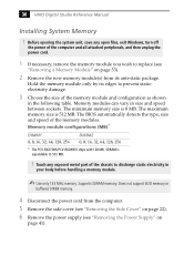
..., 64, 128, 256 * The PCV-RX270DS/PCV-RX280DS ships with 128 MB. 30 VAIO Digital Studio Reference Manual Installing System Memory ! The maximum memory size is 8 MB. SDRAM is expandable to discharge static electricity in your body before handling a memory module. ✍ Use only 133 MHz memory. Supports SDRAM memory. Does not support EDO memory or buffered DIMM memory. 4 Disconnect the power cord...
..., 64, 128, 256 * The PCV-RX270DS/PCV-RX280DS ships with 128 MB. 30 VAIO Digital Studio Reference Manual Installing System Memory ! The maximum memory size is 8 MB. SDRAM is expandable to discharge static electricity in your body before handling a memory module. ✍ Use only 133 MHz memory. Supports SDRAM memory. Does not support EDO memory or buffered DIMM memory. 4 Disconnect the power cord...

Reference Manual
Page 45
..., and Replacing Components 31 7 Align the module over the appropriate socket, noting the location of the module. Press down here Handles Pin 1 side DIMM2 DIMM1 Memory module (DIMM) 1 Indicates pin 1 OM04586.VSD 8 Carefully but firmly insert the edge of the module into the socket. 9 Press down on each side of the...
..., and Replacing Components 31 7 Align the module over the appropriate socket, noting the location of the module. Press down here Handles Pin 1 side DIMM2 DIMM1 Memory module (DIMM) 1 Indicates pin 1 OM04586.VSD 8 Carefully but firmly insert the edge of the module into the socket. 9 Press down on each side of the...

Reference Manual
Page 46
32 VAIO Digital Studio Reference Manual 12 Reconnect the power cord and turn on the computer. Your computer automatically recognizes the extra memory and will configure itself accordingly when you turn on the computer. No further action is required.
32 VAIO Digital Studio Reference Manual 12 Reconnect the power cord and turn on the computer. Your computer automatically recognizes the extra memory and will configure itself accordingly when you turn on the computer. No further action is required.

Reference Manual
Page 47
KY0073.VSD ✍ The memory modules are located beneath the power supply. Before opening the system unit, save any open files, exit Windows, turn off the power of the computer and all attached peripherals, and then unplug the power cord. 1 Remove the side cover (see "Removing the Side Cover" on ...page 22). 2 Remove the power supply (see "Removing the Power Supply" on page 41). 3 Locate the memory module you wish to remove a memory module if you change the memory...
KY0073.VSD ✍ The memory modules are located beneath the power supply. Before opening the system unit, save any open files, exit Windows, turn off the power of the computer and all attached peripherals, and then unplug the power cord. 1 Remove the side cover (see "Removing the Side Cover" on ...page 22). 2 Remove the power supply (see "Removing the Power Supply" on page 41). 3 Locate the memory module you wish to remove a memory module if you change the memory...

Reference Manual
Page 48
Push out Handles KY0042.VSD 5 Grasp one edge of the chassis to eject the module from its socket. Touch any exposed metal part of the memory module and lift out. 34 VAIO Digital Studio Reference Manual 4 Reach around each side of the power supply and push down the handle on each side of the memory module to discharge static electricity in a static-free bag. ! Store the module in your body before handling the memory module.
Push out Handles KY0042.VSD 5 Grasp one edge of the chassis to eject the module from its socket. Touch any exposed metal part of the memory module and lift out. 34 VAIO Digital Studio Reference Manual 4 Reach around each side of the power supply and push down the handle on each side of the memory module to discharge static electricity in a static-free bag. ! Store the module in your body before handling the memory module.

Reference Manual
Page 55
Removing, Installing, and Replacing Components 41 Removing the Power Supply You remove the power supply when you insert a memory module (see "Installing System Memory" on top of the chassis. 2 Pull the tab (A) that latches the power supply to the chassis. A KY0096.VSD 3 Slide the power supply up until the power supply clears the chassis. 4 Rotate the power supply upside down and rest it on page 30). 1 Remove the screw that secures the power supply to the rear of the chassis where the hard drive is located.
Removing, Installing, and Replacing Components 41 Removing the Power Supply You remove the power supply when you insert a memory module (see "Installing System Memory" on top of the chassis. 2 Pull the tab (A) that latches the power supply to the chassis. A KY0096.VSD 3 Slide the power supply up until the power supply clears the chassis. 4 Rotate the power supply upside down and rest it on page 30). 1 Remove the screw that secures the power supply to the rear of the chassis where the hard drive is located.

Reference Manual
Page 57
Keyboard, Mouse USB1, USB2, Ethernet Serial, Printer, i.LINK 1394 Header 2 Game Mic In, Line In, Line Out 1394 Header 3 CD-In Video Aux-In Processor CPU Fan Memory Slot 3 (PCI) Slot 2 (PCI) Slot 1 (PCI) Power Supply Fan Power Supply Secondary IDE Primary IDE Diskette AGP USB23 Header Battery Configuration Jumpers Front panel header OM04581.VSD 43 Chapter 4 System Board This chapter identifies each component on the system board and provides a detailed description of each connector, jumper, and switch on the system board.
Keyboard, Mouse USB1, USB2, Ethernet Serial, Printer, i.LINK 1394 Header 2 Game Mic In, Line In, Line Out 1394 Header 3 CD-In Video Aux-In Processor CPU Fan Memory Slot 3 (PCI) Slot 2 (PCI) Slot 1 (PCI) Power Supply Fan Power Supply Secondary IDE Primary IDE Diskette AGP USB23 Header Battery Configuration Jumpers Front panel header OM04581.VSD 43 Chapter 4 System Board This chapter identifies each component on the system board and provides a detailed description of each connector, jumper, and switch on the system board.

Reference Manual
Page 60
The side with pin 1 has a small "1" to orient a DIMM correctly in the DIMM connector (a small triangle on the connector indicates pin 1). Be sure to the left of each Dual Inline Memory Module (DIMM) look very similar. Memory module (DIMM) 1 Indicates pin 1 OM04908B.VSD 46 VAIO Digital Studio Reference Manual Memory Module (DIMM) Connectors DIMM1 DIMM2 OM04710A.VSD Both sides of pin 1.
The side with pin 1 has a small "1" to orient a DIMM correctly in the DIMM connector (a small triangle on the connector indicates pin 1). Be sure to the left of each Dual Inline Memory Module (DIMM) look very similar. Memory module (DIMM) 1 Indicates pin 1 OM04908B.VSD 46 VAIO Digital Studio Reference Manual Memory Module (DIMM) Connectors DIMM1 DIMM2 OM04710A.VSD Both sides of pin 1.

Reference Manual
Page 88
... Enabled OS/2 Onboard Memory > 64M [Disabled] Enabled Chip Configuration (see "Chip Configuration Sub-Menu" on page 75) I/O Device Configuration (see "I/O Device Configuration Sub-Menu" on page 76) PCI Configuration (see "PCI Configuration Sub-Menu" on page 77) Shadow Configuration (see "Shadow Configuration Sub-Menu" on page 79) 74 VAIO Digital Studio Reference Manual Advanced...
... Enabled OS/2 Onboard Memory > 64M [Disabled] Enabled Chip Configuration (see "Chip Configuration Sub-Menu" on page 75) I/O Device Configuration (see "I/O Device Configuration Sub-Menu" on page 76) PCI Configuration (see "PCI Configuration Sub-Menu" on page 77) Shadow Configuration (see "Shadow Configuration Sub-Menu" on page 79) 74 VAIO Digital Studio Reference Manual Advanced...

Reference Manual
Page 89
... CAS Delay* SDRAM RAS Precharge Time* SDRAM Cycle Time (Tras, Trc) SDRAM Page Closing Policy CPU Latency Timer CPC Graphics Window Size Video Memory Cache Mode AGP 4X Support Memory Hole At 15M-16M PCI 2.1 Support High Priority PCI Mode Onboard PCI IDE Enable [By SPD] User Define [3T] [3T] [3T] [6T...
... CAS Delay* SDRAM RAS Precharge Time* SDRAM Cycle Time (Tras, Trc) SDRAM Page Closing Policy CPU Latency Timer CPC Graphics Window Size Video Memory Cache Mode AGP 4X Support Memory Hole At 15M-16M PCI 2.1 Support High Priority PCI Mode Onboard PCI IDE Enable [By SPD] User Define [3T] [3T] [3T] [6T...

Reference Manual
Page 99
Chapter 8 Miscellaneous Technical Information This chapter contains information on the following subjects: ❑ User and Supervisor password ❑ Beep code error messages ❑ PCI configuration status and error messages ❑ DMA channel assignments ❑ IRQ assignments ❑ System I/O address map ❑ Memory map ❑ PCI configuration space map 85
Chapter 8 Miscellaneous Technical Information This chapter contains information on the following subjects: ❑ User and Supervisor password ❑ Beep code error messages ❑ PCI configuration status and error messages ❑ DMA channel assignments ❑ IRQ assignments ❑ System I/O address map ❑ Memory map ❑ PCI configuration space map 85

Reference Manual
Page 102
... Data Invalid, NVRAM Cleared Parallel Port Resource Conflict PCI Error Log is Full PCI I/O Port Conflict PCI IRQ Conflict PCI Memory Conflict Primary Boot Device Not Found Primary IDE Controller Resource Conflict Primary Input Device Not Found Primary Output Device Not Found Secondary... list of status and error messages that is already in use. Two devices requested the same resource, resulting in a conflict. 88 VAIO Digital Studio Reference Manual PCI Configuration Status and Error Messages The following is already in use. The NVRAM data was reinitialized due to the clear ...
... Data Invalid, NVRAM Cleared Parallel Port Resource Conflict PCI Error Log is Full PCI I/O Port Conflict PCI IRQ Conflict PCI Memory Conflict Primary Boot Device Not Found Primary IDE Controller Resource Conflict Primary Input Device Not Found Primary Output Device Not Found Secondary... list of status and error messages that is already in use. Two devices requested the same resource, resulting in a conflict. 88 VAIO Digital Studio Reference Manual PCI Configuration Status and Error Messages The following is already in use. The NVRAM data was reinitialized due to the clear ...

Reference Manual
Page 104
DMA Channel 02 04 Default Assignment Standard floppy disk controller. Direct memory access (DMA) controller. 90 VAIO Digital Studio Reference Manual DMA Channel Assignments This shows the factory default values. Windows reassigns resources to best meet the needs of a particular configuration.
DMA Channel 02 04 Default Assignment Standard floppy disk controller. Direct memory access (DMA) controller. 90 VAIO Digital Studio Reference Manual DMA Channel Assignments This shows the factory default values. Windows reassigns resources to best meet the needs of a particular configuration.


