Quick Start Guide
Page 3
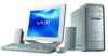
..., printers, facsimiles and copiers. PS/2 is a U.S. As an ENERGY STAR® Partner, Sony Corporation has determined that this product meets the ENERGY STAR® guidelines for Canadian customers: Your new VAIO® computer includes certain software versions or upgrades, and Internet services or offers that are trademarks or registered trademarks of Advanced Micro Devices...
..., printers, facsimiles and copiers. PS/2 is a U.S. As an ENERGY STAR® Partner, Sony Corporation has determined that this product meets the ENERGY STAR® guidelines for Canadian customers: Your new VAIO® computer includes certain software versions or upgrades, and Internet services or offers that are trademarks or registered trademarks of Advanced Micro Devices...

Quick Start Guide
Page 54
...; Specifications - Your computer is supplied with Sony. ❑ VAIO® Computer User Guide - To access the online manual: 1 Click Start in the text, "View the VAIO® Computer Specifications..." ❑ Preinstalled software Help files - The Quick Start contains information on how to set up your VAIO computer. The online User Guide provides information about configuring, maintaining, upgrading, and troubleshooting...
...; Specifications - Your computer is supplied with Sony. ❑ VAIO® Computer User Guide - To access the online manual: 1 Click Start in the text, "View the VAIO® Computer Specifications..." ❑ Preinstalled software Help files - The Quick Start contains information on how to set up your VAIO computer. The online User Guide provides information about configuring, maintaining, upgrading, and troubleshooting...

Quick Start Guide
Page 55
... is located in this section, depending on your system is free of purchase. ✍ Your computer may not be supplied with your VAIO® computer does not provide an immediate solution or you would like to many frequently asked questions. 55 You...and support information for the preinstalled software on your computer, see the online specifications sheet. The Sony Computing Support Web site provides: ❑ Information about your specific model computer, such as ❑ hardware and software specifications. ❑ upgrade and maintenance procedures. ❑ safety and legal ...
... is located in this section, depending on your system is free of purchase. ✍ Your computer may not be supplied with your VAIO® computer does not provide an immediate solution or you would like to many frequently asked questions. 55 You...and support information for the preinstalled software on your computer, see the online specifications sheet. The Sony Computing Support Web site provides: ❑ Information about your specific model computer, such as ❑ hardware and software specifications. ❑ upgrade and maintenance procedures. ❑ safety and legal ...
System Reference Manual
Page 2
...the terms and conditions of such software is subject to U.S. Important information for Canadian customers: Your new VAIO® computer includes certain software versions or upgrades, and Internet services or offers that are subject to change without notice and may apply). Reproduction in whole... detailed during initial launch of the software product(s), or upon certain reinstallations of the software product(s), or reconfigurations of Sony. customers only. SONY CANNOT WARRANT THAT THE FUNCTIONS DESCRIBED IN THIS GUIDE WILL BE UNINTERRUPTED OR ERRORFREE. BE LIABLE FOR ANY INCIDENTAL, ...
...the terms and conditions of such software is subject to U.S. Important information for Canadian customers: Your new VAIO® computer includes certain software versions or upgrades, and Internet services or offers that are subject to change without notice and may apply). Reproduction in whole... detailed during initial launch of the software product(s), or upon certain reinstallations of the software product(s), or reconfigurations of Sony. customers only. SONY CANNOT WARRANT THAT THE FUNCTIONS DESCRIBED IN THIS GUIDE WILL BE UNINTERRUPTED OR ERRORFREE. BE LIABLE FOR ANY INCIDENTAL, ...
System Reference Manual
Page 12
... Jumper 52 Chapter 5 - CMOS Setup Options 53 Main Screen 55 Advanced Screen 58 Power Screen 61 Boot Screen 62 Exit Screen 64 xii VAIO Computer System Reference Manual Chapter 3 - Upgrading and Maintaining Components 25 Removing the Cover 26 Removing the cover 26 Replacing the cover 28 Installing an Add-on Card 29 About...
... Jumper 52 Chapter 5 - CMOS Setup Options 53 Main Screen 55 Advanced Screen 58 Power Screen 61 Boot Screen 62 Exit Screen 64 xii VAIO Computer System Reference Manual Chapter 3 - Upgrading and Maintaining Components 25 Removing the Cover 26 Removing the cover 26 Replacing the cover 28 Installing an Add-on Card 29 About...

System Reference Manual
Page 39
Your computer may vary, depending on the model purchased. System configuration may not include all attached peripheral devices, shut down the computer, and unplug the power cord. 25 Before opening the system unit, save and close all open files, exit all open applications, turn off the power to all of the hardware features shown in the illustrations of this section. ! Chapter 3 Upgrading and Maintaining Components This chapter describes upgrade and maintenance procedures.
Your computer may vary, depending on the model purchased. System configuration may not include all attached peripheral devices, shut down the computer, and unplug the power cord. 25 Before opening the system unit, save and close all open files, exit all open applications, turn off the power to all of the hardware features shown in the illustrations of this section. ! Chapter 3 Upgrading and Maintaining Components This chapter describes upgrade and maintenance procedures.

System Reference Manual
Page 41
Slide the cover towards the back of the system unit cool down your computer, the components may be too hot to touch. Wait until the internal parts of the unit to remove the cover. Upgrading and Maintaining Components 27 5 When the screws are removed, the cover is released. Removing the cover ! If you remove the cover immediately after you shut down before you attempt to remove it.
Slide the cover towards the back of the system unit cool down your computer, the components may be too hot to touch. Wait until the internal parts of the unit to remove the cover. Upgrading and Maintaining Components 27 5 When the screws are removed, the cover is released. Removing the cover ! If you remove the cover immediately after you shut down before you attempt to remove it.

System Reference Manual
Page 43
...more open expansion slots, depending on the model configuration. An expansion slot enables you want to remove. The length of your Sony computer. Installing an add-on card 1 Shut down your computer and any peripheral devices. 3 Remove the cover. Remove the slot cover's screw, and then remove the slot cover. !... the functionality of the add-on card should not exceed 9.05 inches. ✍ Add-on card configuration varies by model. Upgrading and Maintaining Components 29 Installing an Add-on Card Your computer may be careful not to damage components on the system board or add-on cards.
...more open expansion slots, depending on the model configuration. An expansion slot enables you want to remove. The length of your Sony computer. Installing an add-on card 1 Shut down your computer and any peripheral devices. 3 Remove the cover. Remove the slot cover's screw, and then remove the slot cover. !... the functionality of the add-on card should not exceed 9.05 inches. ✍ Add-on card configuration varies by model. Upgrading and Maintaining Components 29 Installing an Add-on Card Your computer may be careful not to damage components on the system board or add-on cards.

System Reference Manual
Page 45
See "Replacing the cover." 8 Reconnect the power cord and all peripheral devices. 9 Turn on card. 7 Replace the cover. See the instructions supplied with the add-on the computer. Upgrading and Maintaining Components 31 Installing an add-on card 6 Attach any internal cables that the card requires.
See "Replacing the cover." 8 Reconnect the power cord and all peripheral devices. 9 Turn on card. 7 Replace the cover. See the instructions supplied with the add-on the computer. Upgrading and Maintaining Components 31 Installing an add-on card 6 Attach any internal cables that the card requires.

System Reference Manual
Page 47
Upgrading and Maintaining Components 33 Installing a lithium battery (PCV-RS320 series model) Battery Holder Tab Battery Holder
Upgrading and Maintaining Components 33 Installing a lithium battery (PCV-RS320 series model) Battery Holder Tab Battery Holder
System Reference Manual
Page 49
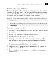
...to gently eject it from your local retailer. ! If necessary, remove any peripheral devices. 3 Remove the cover. Store the module in your computer. ✍ You can purchase additional memory modules, accessories, and peripheral equipment from the slot. 7 Grasp one edge of the module and ... the unit on the system configuration you wish to access the memory module slots. 5 Locate the memory module(s) you purchased. Upgrading and Maintaining Components 35 About Installing Memory The amount of preinstalled memory may ship with all peripheral devices, such as your printer. 2 ...
...to gently eject it from your local retailer. ! If necessary, remove any peripheral devices. 3 Remove the cover. Store the module in your computer. ✍ You can purchase additional memory modules, accessories, and peripheral equipment from the slot. 7 Grasp one edge of the module and ... the unit on the system configuration you wish to access the memory module slots. 5 Locate the memory module(s) you purchased. Upgrading and Maintaining Components 35 About Installing Memory The amount of preinstalled memory may ship with all peripheral devices, such as your printer. 2 ...

System Reference Manual
Page 51
The latches snap into place. 9 Reinstall any components or add-on cards you may have removed. 10 Replace the cover. Upgrading and Maintaining Components 37 8 Press down evenly against the module's upper corners. To avoid damaging a memory module slot, move the end latches slightly outward to relieve pressure. See "Replacing the cover." The module clicks into position, holding the module in place. !
The latches snap into place. 9 Reinstall any components or add-on cards you may have removed. 10 Replace the cover. Upgrading and Maintaining Components 37 8 Press down evenly against the module's upper corners. To avoid damaging a memory module slot, move the end latches slightly outward to relieve pressure. See "Replacing the cover." The module clicks into position, holding the module in place. !
System Reference Manual
Page 53
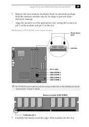
... here Latches Pin 1 side DDR-DIMM 4 DDR-DIMM 3 DDR-DIMM 2 DDR-DIMM 1 ✍ The PCV-RS310 series model has only two memory module slots on the slot. Hold the memory module only by its anti-static package. Upgrading and Maintaining Components 39 6 Remove the new memory module(s) from its edges to prevent staticelectricity...
... here Latches Pin 1 side DDR-DIMM 4 DDR-DIMM 3 DDR-DIMM 2 DDR-DIMM 1 ✍ The PCV-RS310 series model has only two memory module slots on the slot. Hold the memory module only by its anti-static package. Upgrading and Maintaining Components 39 6 Remove the new memory module(s) from its edges to prevent staticelectricity...

System Reference Manual
Page 55
This may damage some components, especially the main processor, which generates the most heat. ! Upgrading and Maintaining Components 41 Covering an Open I /O slot cover. If air escapes, the components inside the computer cannot be properly cooled. All add-on card brackets and slot covers rest on the lip in the ... system unit, save and close all open files, exit all open applications, turn off the power to all attached peripheral devices, shut down the computer, and unplug the power cord. 1 Slide the tip of the slot cover between the chassis and system board. 2 Push the slot cover down...
This may damage some components, especially the main processor, which generates the most heat. ! Upgrading and Maintaining Components 41 Covering an Open I /O slot cover. If air escapes, the components inside the computer cannot be properly cooled. All add-on card brackets and slot covers rest on the lip in the ... system unit, save and close all open files, exit all open applications, turn off the power to all attached peripheral devices, shut down the computer, and unplug the power cord. 1 Slide the tip of the slot cover between the chassis and system board. 2 Push the slot cover down...

System Reference Manual
Page 56
...precautions when you upgrade your system's features. ✍ The hard disk drive access indicator is lit when either internal hard disk drive is a quick and easy-to-use program that can support ATA-33, ATA-66, or ATA-100 hard disk drives. 42 VAIO Computer System Reference ...Manual About Hard Disk Drive Installation Your computer comes with the VAIO Recovery utility, you can purchase a Partition Recovery CD Assembly (Partition Recovery ASSY) to restore your system. Sony recommends using an ATA-100 hard disk drive to ...
...precautions when you upgrade your system's features. ✍ The hard disk drive access indicator is lit when either internal hard disk drive is a quick and easy-to-use program that can support ATA-33, ATA-66, or ATA-100 hard disk drives. 42 VAIO Computer System Reference ...Manual About Hard Disk Drive Installation Your computer comes with the VAIO Recovery utility, you can purchase a Partition Recovery CD Assembly (Partition Recovery ASSY) to restore your system. Sony recommends using an ATA-100 hard disk drive to ...

System Reference Manual
Page 57
... chassis by removing the drive holder screw. 7 Slide the drive holder out. Removing the drive holder Upgrading and Maintaining Components 43 Installing an additional hard disk drive 1 Shut down your computer and turn off all peripheral devices, such as a slave. See "Removing the Cover." 4 Configure ...the jumpers on the new drive as your printer. 2 Unplug your computer. 6 Release the drive holder from the original hard disk...
... chassis by removing the drive holder screw. 7 Slide the drive holder out. Removing the drive holder Upgrading and Maintaining Components 43 Installing an additional hard disk drive 1 Shut down your computer and turn off all peripheral devices, such as a slave. See "Removing the Cover." 4 Configure ...the jumpers on the new drive as your printer. 2 Unplug your computer. 6 Release the drive holder from the original hard disk...

System Reference Manual
Page 59
Upgrading and Maintaining Components 45 Replacing the drive holder 14 Replace the cover. A shortcut menu appears. 3 Select Manage. The Computer Management window appears. 4 Under the file directory, go to your computer. See "Replacing the cover." 15 Reconnect the power cord to Storage and then select Disk Management.... 5 Right-click on to Windows® as Administrator. 2 Click Start in the Windows taskbar, then right-click My Computer. From the shortcut menu, select Initialize Disk. Identifying the additional hard disk space When you initialize the new hard disk, it ...
Upgrading and Maintaining Components 45 Replacing the drive holder 14 Replace the cover. A shortcut menu appears. 3 Select Manage. The Computer Management window appears. 4 Under the file directory, go to your computer. See "Replacing the cover." 15 Reconnect the power cord to Storage and then select Disk Management.... 5 Right-click on to Windows® as Administrator. 2 Click Start in the Windows taskbar, then right-click My Computer. From the shortcut menu, select Initialize Disk. Identifying the additional hard disk space When you initialize the new hard disk, it ...

System Reference Manual
Page 61
...to all attached peripheral devices, shut down and rest it on page 38). ! Removing the power supply A 4 Rotate the power supply upside down the computer, and unplug the power cord. 1 Remove the screw that latches the power supply to the chassis. 3 Slide the power supply up until the power... supply clears the chassis. Upgrading and Maintaining Components 47 Removing the Power Supply Remove the power supply when you insert a memory module (see "Installing Memory Modules" on top of...
...to all attached peripheral devices, shut down and rest it on page 38). ! Removing the power supply A 4 Rotate the power supply upside down the computer, and unplug the power cord. 1 Remove the screw that latches the power supply to the chassis. 3 Slide the power supply up until the power... supply clears the chassis. Upgrading and Maintaining Components 47 Removing the Power Supply Remove the power supply when you insert a memory module (see "Installing Memory Modules" on top of...
System Reference Manual
Page 99
See BIOS CMOS Clear configuration jumper 52 CMOS RAM 32 codes, beeps 67 communications, specifications 81 computer add-on card installation 29 lithium battery ix memory upgrade 35 removing unit cover 26 replacing lithium battery 32 configuration jumper, CMOS Clear 52 configuring BIOS setup utility 18 power management 19 connectors i.LINK 6 USB 6 ...
See BIOS CMOS Clear configuration jumper 52 CMOS RAM 32 codes, beeps 67 communications, specifications 81 computer add-on card installation 29 lithium battery ix memory upgrade 35 removing unit cover 26 replacing lithium battery 32 configuration jumper, CMOS Clear 52 configuring BIOS setup utility 18 power management 19 connectors i.LINK 6 USB 6 ...

System Reference Manual
Page 100
...mic 14 monitor 13 mouse 12 printer 13 telephone 14 USB 12 I/O slot covering 41 icons, description of discs 3, 83 86 VAIO Computer System Reference Manual G Giga Pocket initialize additional hard disk drive 45 graphics controller - See processor modem - See graphics graphics specifications 80...14 I i.LINK connector 6, 15 I/O address map 72 slot specifications 82 I /O address map and memory map memory installing 36 removing 35 upgrading 35 memory - See display monitor connector 13 mouse connector 12 N NTFS file format 45 O online specifications 1 Optical drive location of 3 ...
...mic 14 monitor 13 mouse 12 printer 13 telephone 14 USB 12 I/O slot covering 41 icons, description of discs 3, 83 86 VAIO Computer System Reference Manual G Giga Pocket initialize additional hard disk drive 45 graphics controller - See processor modem - See graphics graphics specifications 80...14 I i.LINK connector 6, 15 I/O address map 72 slot specifications 82 I /O address map and memory map memory installing 36 removing 35 upgrading 35 memory - See display monitor connector 13 mouse connector 12 N NTFS file format 45 O online specifications 1 Optical drive location of 3 ...


