
User Guide
Page 26
... the camera, turn off the power on the same tape. You should perform a separate capture for tapes recorded in the flash memory of your digital video device is saved in LP mode. ❑ For tapes that you wish to your selected [OUT] point. Using DVgate ... to tape by the capture progress indicator may not be due to turn the power back on. VAIO Digital Studio™ Computer User Guide Using Digital Video Connecting a Digital Video Recorder Before connecting a digital video camera recorder to use. ❑ DVgate does not support hard disk compression. You should disable...
... the camera, turn off the power on the same tape. You should perform a separate capture for tapes recorded in the flash memory of your digital video device is saved in LP mode. ❑ For tapes that you wish to your selected [OUT] point. Using DVgate ... to tape by the capture progress indicator may not be due to turn the power back on. VAIO Digital Studio™ Computer User Guide Using Digital Video Connecting a Digital Video Recorder Before connecting a digital video camera recorder to use. ❑ DVgate does not support hard disk compression. You should disable...

User Guide
Page 43
... that are not currently using. ❑ Increasing the system memory may also help. Topic: My connected printer doesn't function after the computer resumes from your peripheral. 3 Then turn on the desktop and select Properties. 2 Click the Device Manager tab. 3...procedures below to reset the printer connection: 1 Right-click the My Computer icon on installing memory, please see the online document Upgrading and Maintaining Your VAIO® Computer. The computer has two memory slots. Sony computer supplies, accessories and peripherals can be purchased from a power saving mode...
... that are not currently using. ❑ Increasing the system memory may also help. Topic: My connected printer doesn't function after the computer resumes from your peripheral. 3 Then turn on the desktop and select Properties. 2 Click the Device Manager tab. 3...procedures below to reset the printer connection: 1 Right-click the My Computer icon on installing memory, please see the online document Upgrading and Maintaining Your VAIO® Computer. The computer has two memory slots. Sony computer supplies, accessories and peripherals can be purchased from a power saving mode...

User Guide
Page 55
...-45) 55 CD-R reading, 4X max. Specifications PCV-R553DS Specifications PCV-R553DS Model PCV-R553DS Processor Hard Disk Drive 650 MHz* Pentium® III 30 GB† Standard SDRAM 128 MB PC-100 SDRAM, expandable to 256 MB Video RAM Shared with system memory MPEG "Sony Tuned" MPEG Digital Video supports full-screen video playback Graphics...
...-45) 55 CD-R reading, 4X max. Specifications PCV-R553DS Specifications PCV-R553DS Model PCV-R553DS Processor Hard Disk Drive 650 MHz* Pentium® III 30 GB† Standard SDRAM 128 MB PC-100 SDRAM, expandable to 256 MB Video RAM Shared with system memory MPEG "Sony Tuned" MPEG Digital Video supports full-screen video playback Graphics...

Reference Manual
Page 12
...62 Headphones, Line In, Mic Connectors 63 i.LINK Header Connectors 64 CD-IN Connector 65 AUX-IN Connector 66 Configuration Jumpers 67 xii VAIO Digital Studio™ Reference Manual Chapter 3 - Removing, Installing, and Replacing Components Removing the Cover 22 Removing the Front Panel 24 Replacing the Front...Replacing the Cover 26 Installing an Add-In Card 28 Removing an Add-in Card 29 Replacing the Lithium Battery 31 Installing System Memory 34 Removing a Memory Module 37 Removing a Slot Cover 39 Covering an Open I/O Slot 40 Installing a 3½" Internal Hard Disk Drive 41 ...
...62 Headphones, Line In, Mic Connectors 63 i.LINK Header Connectors 64 CD-IN Connector 65 AUX-IN Connector 66 Configuration Jumpers 67 xii VAIO Digital Studio™ Reference Manual Chapter 3 - Removing, Installing, and Replacing Components Removing the Cover 22 Removing the Front Panel 24 Replacing the Front...Replacing the Cover 26 Installing an Add-In Card 28 Removing an Add-in Card 29 Replacing the Lithium Battery 31 Installing System Memory 34 Removing a Memory Module 37 Removing a Slot Cover 39 Covering an Open I/O Slot 40 Installing a 3½" Internal Hard Disk Drive 41 ...

Reference Manual
Page 13
... 69 Chapter 6 - Video Card Chapter 7 - Specifications Processors 97 Chipset ...97 AGP Bus ...97 PCI Bus ...97 Memory Modules (DIMMs 97 DIMM Configurations 98 L2 Cache ...98 Graphics ...98 Audio ...98 Communications 99 I /O Address Map 93 Memory Map 95 Chapter 9 - CMOS Setup Options Main Screen 75 Advanced Screen 77 Power Screen 83 Boot...
... 69 Chapter 6 - Video Card Chapter 7 - Specifications Processors 97 Chipset ...97 AGP Bus ...97 PCI Bus ...97 Memory Modules (DIMMs 97 DIMM Configurations 98 L2 Cache ...98 Graphics ...98 Audio ...98 Communications 99 I /O Address Map 93 Memory Map 95 Chapter 9 - CMOS Setup Options Main Screen 75 Advanced Screen 77 Power Screen 83 Boot...
Reference Manual
Page 36
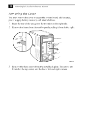
22 VAIO Digital Studio Reference Manual Removing the Cover You must remove the cover to right. The screws are located at the top center, and the lower left to access the system board, add-in cards, power supply, battery, memory, and internal drives. 1 From the rear of the unit, press the two tabs on the right side. 2 Remove the frame from the unit by gently pulling it from the metal back plate. KY0064B.VSD 3 Remove the three screws from left and right corners.
22 VAIO Digital Studio Reference Manual Removing the Cover You must remove the cover to right. The screws are located at the top center, and the lower left to access the system board, add-in cards, power supply, battery, memory, and internal drives. 1 From the rear of the unit, press the two tabs on the right side. 2 Remove the frame from the unit by gently pulling it from the metal back plate. KY0064B.VSD 3 Remove the three screws from left and right corners.

Reference Manual
Page 45
...replacing the battery, it is safer to assume that are lost . When the values are different from the Start menu, and then selecting Restart the computer. 2 If the error message "Error: Check date and time settings"appears during the reboot sequence, press F2 during the reboot process to access ...the BIOS Setup Utility. You will be too weak to power the CMOS memory. ! When you restore the BIOS settings later. 4 Select Exit Discarding Changes from the main menu using the right arrow key. 5 Press Enter, type Y...
...replacing the battery, it is safer to assume that are lost . When the values are different from the Start menu, and then selecting Restart the computer. 2 If the error message "Error: Check date and time settings"appears during the reboot sequence, press F2 during the reboot process to access ...the BIOS Setup Utility. You will be too weak to power the CMOS memory. ! When you restore the BIOS settings later. 4 Select Exit Discarding Changes from the main menu using the right arrow key. 5 Press Enter, type Y...

Reference Manual
Page 48
... VAIO Digital Studio Reference Manual Installing System Memory ! Before opening the system unit, save any exposed metal part of the computer and all attached peripherals, and then unplug the power cord. 1 If necessary, remove the memory module you wish to discharge static electricity in your body before handling a memory module. ✍ Use only 133 MHz FSB-supported memory...
... VAIO Digital Studio Reference Manual Installing System Memory ! Before opening the system unit, save any exposed metal part of the computer and all attached peripherals, and then unplug the power cord. 1 If necessary, remove the memory module you wish to discharge static electricity in your body before handling a memory module. ✍ Use only 133 MHz FSB-supported memory...

Reference Manual
Page 49
Press down here Handles Pin 1 side DIMM2 DIMM1 Memory module (DIMM) 1 8 Carefully but firmly insert the edge of the module into the socket. 9 Press down firmly and evenly at both corners until the handles ...
Press down here Handles Pin 1 side DIMM2 DIMM1 Memory module (DIMM) 1 8 Carefully but firmly insert the edge of the module into the socket. 9 Press down firmly and evenly at both corners until the handles ...

Reference Manual
Page 50
No further action is required. Your computer automatically recognizes the extra memory and will configure itself accordingly when you turn on the computer. 36 VAIO Digital Studio Reference Manual 12 Reconnect the power cord and turn on the computer.
No further action is required. Your computer automatically recognizes the extra memory and will configure itself accordingly when you turn on the computer. 36 VAIO Digital Studio Reference Manual 12 Reconnect the power cord and turn on the computer.

Reference Manual
Page 51
...you wish to reach the memory modules. Removing, Installing, and Replacing Components 37 Removing a Memory Module You may need to remove the power supply to remove. Before opening the system unit, save any open files, exit Windows, turn off the power of the computer and all attached peripherals, and... then unplug the power cord. 13 Remove the cover (see "Removing the Cover" on page 22). 14 Locate the memory module you change the memory configuration or replace a bad module. !
...you wish to reach the memory modules. Removing, Installing, and Replacing Components 37 Removing a Memory Module You may need to remove the power supply to remove. Before opening the system unit, save any open files, exit Windows, turn off the power of the computer and all attached peripherals, and... then unplug the power cord. 13 Remove the cover (see "Removing the Cover" on page 22). 14 Locate the memory module you change the memory configuration or replace a bad module. !

Reference Manual
Page 52
Touch any exposed metal part of the chassis to eject the module from its socket. Push out Handles KY00 16 Grasp one edge of the memory module to discharge static electricity in a static-free bag. ! Store the module in your body before handling the memory module. 38 VAIO Digital Studio Reference Manual 15 Reach around each side of the power supply and push down the handle on each side of the memory module and lift out.
Touch any exposed metal part of the chassis to eject the module from its socket. Push out Handles KY00 16 Grasp one edge of the memory module to discharge static electricity in a static-free bag. ! Store the module in your body before handling the memory module. 38 VAIO Digital Studio Reference Manual 15 Reach around each side of the power supply and push down the handle on each side of the memory module and lift out.

Reference Manual
Page 59
Removing, Installing, and Replacing Components 45 Removing the Power Supply You remove the power supply when you insert a memory module (see "Installing System Memory" on page 34). 1 Remove the three screws (A in next diagram) from the rear of the chassis. 2 Remove the screw (B) from the power supply bracket. A B KY0096.VSD
Removing, Installing, and Replacing Components 45 Removing the Power Supply You remove the power supply when you insert a memory module (see "Installing System Memory" on page 34). 1 Remove the three screws (A in next diagram) from the rear of the chassis. 2 Remove the screw (B) from the power supply bracket. A B KY0096.VSD

Reference Manual
Page 63
Keyboard, Mouse USB1, USB2, Ethernet COM1, Printer, i.LINK 1394 Header 2 Game Mic In, Line In, Line Out 1394 Header 3 CD-In Video Aux-In Processor CPU Fan Memory Slot 3 (PCI) Slot 2 (PCI) Slot 1 (PCI) Power Supply Fan Power Supply Secondary IDE Primary IDE Diskette AGP USB2 Header Battery Configuration Jumpers Front panel header OM04581.VSD 49 Chapter 4 System Board This chapter identifies each component on the system board and provides a detailed description of each connector, jumper, and switch on the system board.
Keyboard, Mouse USB1, USB2, Ethernet COM1, Printer, i.LINK 1394 Header 2 Game Mic In, Line In, Line Out 1394 Header 3 CD-In Video Aux-In Processor CPU Fan Memory Slot 3 (PCI) Slot 2 (PCI) Slot 1 (PCI) Power Supply Fan Power Supply Secondary IDE Primary IDE Diskette AGP USB2 Header Battery Configuration Jumpers Front panel header OM04581.VSD 49 Chapter 4 System Board This chapter identifies each component on the system board and provides a detailed description of each connector, jumper, and switch on the system board.

Reference Manual
Page 66
The side with pin 1 has a small "1" to orient a DIMM correctly in the DIMM connector (a small triangle on the connector indicates pin 1). Be sure to the left of each Dual Inline Memory Module (DIMM) look very similar. Memory module (DIMM) 1 Indicates pin 1 OM04908B.VSD 52 VAIO Digital Studio Reference Manual Memory Module (DIMM) Connectors DIMM1 DIMM2 OM04710A.VSD Both sides of pin 1.
The side with pin 1 has a small "1" to orient a DIMM correctly in the DIMM connector (a small triangle on the connector indicates pin 1). Be sure to the left of each Dual Inline Memory Module (DIMM) look very similar. Memory module (DIMM) 1 Indicates pin 1 OM04908B.VSD 52 VAIO Digital Studio Reference Manual Memory Module (DIMM) Connectors DIMM1 DIMM2 OM04710A.VSD Both sides of pin 1.
Reference Manual
Page 89
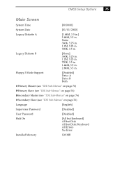
...) Language [English] Supervisor Password [Disabled] User Password [Disabled] Halt On [All but Keyboard] All but Disk All but Disk/Keyboard All Errors No Error Installed Memory 128 MB None 360K, 5.25 in. 1.2M, 5.25 in. 720K, 3.5 in . Legacy Diskette B [None] 360K, 5.25 in. 1.2M, 5.25 in. 720K, 3.5 in. 1.44M, 3.5 in. 2.88M...
...) Language [English] Supervisor Password [Disabled] User Password [Disabled] Halt On [All but Keyboard] All but Disk All but Disk/Keyboard All Errors No Error Installed Memory 128 MB None 360K, 5.25 in. 1.2M, 5.25 in. 720K, 3.5 in . Legacy Diskette B [None] 360K, 5.25 in. 1.2M, 5.25 in. 720K, 3.5 in. 1.44M, 3.5 in. 2.88M...

Reference Manual
Page 91
... CPU Level 2 Cache ECC Check [Disabled] Enabled BIOS Update [Enabled] Disabled PS/2 Mouse Function Control [Auto] Enabled USB Legacy Support [Auto] Disabled Enabled OS/2 Onboard Memory > 64M [Disabled] Enabled Chip Configuration (see "Chip Configuration Sub-Menu" on page 78) I/O Device Configuration (see "I/O Device Configuration Sub-Menu" on page 79) PCI Configuration...
... CPU Level 2 Cache ECC Check [Disabled] Enabled BIOS Update [Enabled] Disabled PS/2 Mouse Function Control [Auto] Enabled USB Legacy Support [Auto] Disabled Enabled OS/2 Onboard Memory > 64M [Disabled] Enabled Chip Configuration (see "Chip Configuration Sub-Menu" on page 78) I/O Device Configuration (see "I/O Device Configuration Sub-Menu" on page 79) PCI Configuration...

Reference Manual
Page 92
78 VAIO Digital Studio™ Reference Manual Chip Configuration Sub-Menu SDRAM Configuration SDRAM CAS Latency SDRAM RAS to CAS Delay SDRAM RAS Precharge Time SDRAM Cycle Time (Tras, Trc) SDRAM Page Closing Policy CPU Latency Timer CPC Graphics Video Memory Cache Mode AGP 4X Support Memory Hole At 15M-16M PCI 2.1 Support High Priority PCI...
78 VAIO Digital Studio™ Reference Manual Chip Configuration Sub-Menu SDRAM Configuration SDRAM CAS Latency SDRAM RAS to CAS Delay SDRAM RAS Precharge Time SDRAM Cycle Time (Tras, Trc) SDRAM Page Closing Policy CPU Latency Timer CPC Graphics Video Memory Cache Mode AGP 4X Support Memory Hole At 15M-16M PCI 2.1 Support High Priority PCI...

Reference Manual
Page 101
Chapter 8 Miscellaneous Technical Information This chapter contains information on the following subjects: ❑ User and Supervisor password ❑ Beep code error messages ❑ PCI configuration status and error messages ❑ DMA channel assignments ❑ IRQ assignments ❑ System I/O address map ❑ Memory map ❑ PCI configuration space map 87
Chapter 8 Miscellaneous Technical Information This chapter contains information on the following subjects: ❑ User and Supervisor password ❑ Beep code error messages ❑ PCI configuration status and error messages ❑ DMA channel assignments ❑ IRQ assignments ❑ System I/O address map ❑ Memory map ❑ PCI configuration space map 87

Reference Manual
Page 104
... NVRAM Data Invalid, NVRAM Cleared Parallel Port Resource Conflict PCI Error Log is Full PCI I/O Port Conflict PCI IRQ Conflict PCI Memory Conflict Primary Boot Device Not Found Primary IDE Controller Resource Conflict Primary Input Device Not Found Primary Output Device Not Found Secondary IDE...has requested a resource that is already in use . The primary IDE controller has requested a resource that is already in use . 90 VAIO Digital Studio Reference Manual PCI Configuration Status and Error Messages The following is a list of status and error messages that may appear on your system from...
... NVRAM Data Invalid, NVRAM Cleared Parallel Port Resource Conflict PCI Error Log is Full PCI I/O Port Conflict PCI IRQ Conflict PCI Memory Conflict Primary Boot Device Not Found Primary IDE Controller Resource Conflict Primary Input Device Not Found Primary Output Device Not Found Secondary IDE...has requested a resource that is already in use . The primary IDE controller has requested a resource that is already in use . 90 VAIO Digital Studio Reference Manual PCI Configuration Status and Error Messages The following is a list of status and error messages that may appear on your system from...


