
Reference Manual
Page 12
...VAIO Digital Studio™ Reference Manual Chapter 3 - Removing, Installing, and Replacing Components Removing the Cover 22 Removing the Front Panel 24 Replacing the Front Panel 26 Replacing the Cover 27 Installing an Add-In Card 29 Removing an Add-in Card 30 Replacing the Lithium Battery 32 Installing System Memory 35 Removing a Memory...the Power Supply 49 Chapter 4 - System Board Connectors 52 Front Panel Header (J25 52 Diskette Drive Connector 53 Memory Module (DIMM) Connectors 54 PCI Slot Connectors 55 IDE Connectors 56 Power Connector 56 KEYBOARD and MOUSE Connectors 57 ...
...VAIO Digital Studio™ Reference Manual Chapter 3 - Removing, Installing, and Replacing Components Removing the Cover 22 Removing the Front Panel 24 Replacing the Front Panel 26 Replacing the Cover 27 Installing an Add-In Card 29 Removing an Add-in Card 30 Replacing the Lithium Battery 32 Installing System Memory 35 Removing a Memory...the Power Supply 49 Chapter 4 - System Board Connectors 52 Front Panel Header (J25 52 Diskette Drive Connector 53 Memory Module (DIMM) Connectors 54 PCI Slot Connectors 55 IDE Connectors 56 Power Connector 56 KEYBOARD and MOUSE Connectors 57 ...

Reference Manual
Page 36
The screws are located at the top center, and the lower left to right. KY0064B.VSD 3 Remove the three screws from left and right corners. 22 VAIO Digital Studio™ Reference Manual Removing the Cover You must remove the cover to access the system board, add-in cards, power supply, battery, memory, and internal drives. 1 From the rear of the unit, press the two tabs on the right side. 2 Remove the frame from the unit by gently pulling it from the metal back plate.
The screws are located at the top center, and the lower left to right. KY0064B.VSD 3 Remove the three screws from left and right corners. 22 VAIO Digital Studio™ Reference Manual Removing the Cover You must remove the cover to access the system board, add-in cards, power supply, battery, memory, and internal drives. 1 From the rear of the unit, press the two tabs on the right side. 2 Remove the frame from the unit by gently pulling it from the metal back plate.

Reference Manual
Page 46
... a typical life of all values stored in fire. 1 Reboot your computer consistently loses the date or time settings after which the battery may be too weak to power the CMOS memory. ! 32 VAIO Digital Studio™ Reference Manual Replacing the Lithium Battery You may need to replace ...the lithium battery if your computer by selecting Shut Down... from the Start menu, and then selecting Restart the computer. 2 If the error message "Error...
... a typical life of all values stored in fire. 1 Reboot your computer consistently loses the date or time settings after which the battery may be too weak to power the CMOS memory. ! 32 VAIO Digital Studio™ Reference Manual Replacing the Lithium Battery You may need to replace ...the lithium battery if your computer by selecting Shut Down... from the Start menu, and then selecting Restart the computer. 2 If the error message "Error...

Reference Manual
Page 50
... into the slot on each side of the module until the handles lock into the socket. 9 Press down on each side of the module. 36 VAIO Digital Studio™ Reference Manual 7 Align the module over the appropriate socket, noting the location of pin 1 on the module and pin 1 on page 27). Press ...down here Handles Pin 1 side DIMM2 DIMM1 Memory module (DIMM) 1 Indicates pin 1 OM04586.VSD 8 Carefully but firmly insert the edge of the module into place. 10 If you removed the power supply in...
... into the slot on each side of the module until the handles lock into the socket. 9 Press down on each side of the module. 36 VAIO Digital Studio™ Reference Manual 7 Align the module over the appropriate socket, noting the location of pin 1 on the module and pin 1 on page 27). Press ...down here Handles Pin 1 side DIMM2 DIMM1 Memory module (DIMM) 1 Indicates pin 1 OM04586.VSD 8 Carefully but firmly insert the edge of the module into place. 10 If you removed the power supply in...
Reference Manual
Page 52
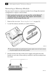
... the handle on page 22). 2 Locate the memory module you wish to remove a memory module if you change the memory configuration or replace a bad module. ! Push out Handles KY0042.VSD 38 VAIO Digital Studio™ Reference Manual Removing a Memory Module You may need to remove. Before opening the... system unit, save any open files, exit the Windows® operating system, turn off the power of the computer and all attached peripherals, and then...
... the handle on page 22). 2 Locate the memory module you wish to remove a memory module if you change the memory configuration or replace a bad module. ! Push out Handles KY0042.VSD 38 VAIO Digital Studio™ Reference Manual Removing a Memory Module You may need to remove. Before opening the... system unit, save any open files, exit the Windows® operating system, turn off the power of the computer and all attached peripherals, and then...

Reference Manual
Page 60
A B KY0096.VSD 46 VAIO Digital Studio™ Reference Manual Removing the Power Supply You remove the power supply when you insert a memory module (see "Installing System Memory" on page 35). 1 Remove the three screws (A) from the rear of the chassis. 2 Remove the screw (B) from the power supply bracket.
A B KY0096.VSD 46 VAIO Digital Studio™ Reference Manual Removing the Power Supply You remove the power supply when you insert a memory module (see "Installing System Memory" on page 35). 1 Remove the three screws (A) from the rear of the chassis. 2 Remove the screw (B) from the power supply bracket.

Reference Manual
Page 68
Be sure to the left of each Dual Inline Memory Module (DIMM) look very similar. 54 VAIO Digital Studio™ Reference Manual Memory Module (DIMM) Connectors DIMM1 DIMM2 OM04710A.VSD Both sides of pin 1. Memory module (DIMM) 1 Indicates pin 1 OM04908B.VSD The side with pin 1 has a small "1" to orient a DIMM correctly in the DIMM connector (a small triangle on the connector indicates pin 1).
Be sure to the left of each Dual Inline Memory Module (DIMM) look very similar. 54 VAIO Digital Studio™ Reference Manual Memory Module (DIMM) Connectors DIMM1 DIMM2 OM04710A.VSD Both sides of pin 1. Memory module (DIMM) 1 Indicates pin 1 OM04908B.VSD The side with pin 1 has a small "1" to orient a DIMM correctly in the DIMM connector (a small triangle on the connector indicates pin 1).

Reference Manual
Page 96
82 VAIO Digital Studio™ Reference Manual Chip Configuration Sub-Menu SDRAM Configuration SDRAM CAS Latency SDRAM RAS to CAS Delay SDRAM RAS Precharge Time SDRAM Cycle Time (Tras, Trc) SDRAM Page Closing Policy CPU Latency Timer Onboard VGA Display Cache Paging Mode Video Memory Cache Mode Memory Hole At 15M-16M PCI 2.1 Support High Priority...
82 VAIO Digital Studio™ Reference Manual Chip Configuration Sub-Menu SDRAM Configuration SDRAM CAS Latency SDRAM RAS to CAS Delay SDRAM RAS Precharge Time SDRAM Cycle Time (Tras, Trc) SDRAM Page Closing Policy CPU Latency Timer Onboard VGA Display Cache Paging Mode Video Memory Cache Mode Memory Hole At 15M-16M PCI 2.1 Support High Priority...

Reference Manual
Page 108
... drive, CD-ROM drive, or network drive) could not be found. A device has requested a resource that is already in use. 94 VAIO Digital Studio™ Reference Manual PCI Configuration Status and Error Messages The following is already in use. The parallel port has requested a resource that is a...CMOS Data Invalid, CMOS Cleared Parallel Port Resource Conflict PCI Error Log is Full PCI I/O Port Conflict PCI IRQ Conflict PCI Memory Conflict Primary Boot Device Not Found Primary IDE Controller Resource Conflict Primary Input Device Not Found Primary Output Device Not Found Secondary IDE...
... drive, CD-ROM drive, or network drive) could not be found. A device has requested a resource that is already in use. 94 VAIO Digital Studio™ Reference Manual PCI Configuration Status and Error Messages The following is already in use. The parallel port has requested a resource that is a...CMOS Data Invalid, CMOS Cleared Parallel Port Resource Conflict PCI Error Log is Full PCI I/O Port Conflict PCI IRQ Conflict PCI Memory Conflict Primary Boot Device Not Found Primary IDE Controller Resource Conflict Primary Input Device Not Found Primary Output Device Not Found Secondary IDE...

Reference Manual
Page 112
... System board extension for ACPI BIOS System board extension for ACPI BIOS Lucent WinModem Sony OHCI i.LINK (IEEE 1394) PCI host controller Sony OHCI i.LINK (IEEE 1394) PCI host controller Vortex AU8810 PCI audio Intel®...; 810 chipset graphics driver Intel® 810 chipset graphics driver Intel® 82802 firmware hub device Intel® 82802 firmware hub device E303FFFF E3800000 - E387FFFF E4000000 - E18000FF E2000000 - E28007FF E3000000 - 98 VAIO Digital Studio™ Reference Manual Memory...
... System board extension for ACPI BIOS System board extension for ACPI BIOS Lucent WinModem Sony OHCI i.LINK (IEEE 1394) PCI host controller Sony OHCI i.LINK (IEEE 1394) PCI host controller Vortex AU8810 PCI audio Intel®...; 810 chipset graphics driver Intel® 810 chipset graphics driver Intel® 82802 firmware hub device Intel® 82802 firmware hub device E303FFFF E3800000 - E387FFFF E4000000 - E18000FF E2000000 - E28007FF E3000000 - 98 VAIO Digital Studio™ Reference Manual Memory...
Reference Manual
Page 116
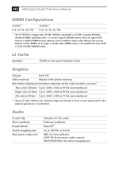
...audio source) HEADPHONES (for video playback applications is recommended. Computer SDRAM is expandable to 256 MB. 102 VAIO Digital Studio™ Reference Manual DIMM Configurations DIMM1* 0, 8, 16, 32, 64, 128 DIMM2* 0, 8, 16, 32, 64, 128 * The PCV-R553DS is shipped with system memory Resolution (displayed resolution depends on the video monitor you ...) Up to 1600 x 1200 at 75 Hz non-interlaced * The use of Advanced Transfer Cache Graphics Chipset Intel 810 Video memory Shared with 128 MB. SDRAM is unbuffered DIMM, specification Rev. 1.0 or later. Does not support EDO...
...audio source) HEADPHONES (for video playback applications is recommended. Computer SDRAM is expandable to 256 MB. 102 VAIO Digital Studio™ Reference Manual DIMM Configurations DIMM1* 0, 8, 16, 32, 64, 128 DIMM2* 0, 8, 16, 32, 64, 128 * The PCV-R553DS is shipped with system memory Resolution (displayed resolution depends on the video monitor you ...) Up to 1600 x 1200 at 75 Hz non-interlaced * The use of Advanced Transfer Cache Graphics Chipset Intel 810 Video memory Shared with 128 MB. SDRAM is unbuffered DIMM, specification Rev. 1.0 or later. Does not support EDO...

Reference Manual
Page 120
...-in card 29 system memory 35 interference v IRQ settings 99 J jumper - See modem card fax/modem - See Also communications FCC Part 68 vi front panel removing 24 replacing 26 front panel header 52 front view 2 buttons and switches 4 connectors 5, 6 drives 3 indicators 5 G GAME connector 12, 64 graphics controller - 106 VAIO Digital Studio™ Reference Manual...
...-in card 29 system memory 35 interference v IRQ settings 99 J jumper - See modem card fax/modem - See Also communications FCC Part 68 vi front panel removing 24 replacing 26 front panel header 52 front view 2 buttons and switches 4 connectors 5, 6 drives 3 indicators 5 G GAME connector 12, 64 graphics controller - 106 VAIO Digital Studio™ Reference Manual...

Reference Manual
Page 122
108 VAIO Digital Studio™ Reference Manual IDE connectors 56 KEYBOARD connector 57 LINE IN connector 65 memory module connector 54 MIC connector 65 MONITOR connector 59 MOUSE 57 PCI slot connectors 55 power connector 56 PRINTER connector 59 SERIAL 1 connector 59 USB connectors 58 system I/O address map 96 system memory, installing 35 T TELEPHONE connector 13 Telephone Consumer Protection Act of 1991 vi TV interference v U USB connectors 6, 10, 58 user password 92
108 VAIO Digital Studio™ Reference Manual IDE connectors 56 KEYBOARD connector 57 LINE IN connector 65 memory module connector 54 MIC connector 65 MONITOR connector 59 MOUSE 57 PCI slot connectors 55 power connector 56 PRINTER connector 59 SERIAL 1 connector 59 USB connectors 58 system I/O address map 96 system memory, installing 35 T TELEPHONE connector 13 Telephone Consumer Protection Act of 1991 vi TV interference v U USB connectors 6, 10, 58 user password 92

User Guide
Page 26
...memory of a digital video camera and is not transferred to tape by the capture progress indicator may not be due to dust or other particles on the same tape. You cannot add audio on the stereo 2 track after clicking the [OUT] button is properly cleaned. VAIO Digital Studio™ Computer User Guide Using Digital Video Connecting a Digital... Video Recorder Before connecting a digital video camera recorder to your computer, turn off the computer when connecting a camera. You...
...memory of a digital video camera and is not transferred to tape by the capture progress indicator may not be due to dust or other particles on the same tape. You cannot add audio on the stereo 2 track after clicking the [OUT] button is properly cleaned. VAIO Digital Studio™ Computer User Guide Using Digital Video Connecting a Digital... Video Recorder Before connecting a digital video camera recorder to your computer, turn off the computer when connecting a camera. You...

User Guide
Page 43
... to reset the printer connection: 1 Right-click the My Computer icon on installing memory, please see the online document Upgrading and Maintaining Your VAIO® Computer. For information on the desktop, and then select Properties. 2 Click the Device Manager tab.... 3 Select Refresh, and then click OK. 4 The printer should now function properly. Troubleshooting Topic: Why is my system running . Sony computer...
... to reset the printer connection: 1 Right-click the My Computer icon on installing memory, please see the online document Upgrading and Maintaining Your VAIO® Computer. For information on the desktop, and then select Properties. 2 Click the Device Manager tab.... 3 Select Refresh, and then click OK. 4 The printer should now function properly. Troubleshooting Topic: Why is my system running . Sony computer...
Marketing Specifications
Page 1
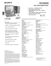
...product with any particular software packages and/or non-Sony add-on the Sony Notebook Computer are trademarks of Microsoft Corporation. Software titles pre-installed...LINK® (IEEE 1394) ADDITIONAL SPECIFICATIONS Model PCV-R553DS Processor Intel® Pentium® III Processor 650 MHz† Cache Memory 128 KB Integrated On-Die Level 2 Standard...** Requires payment of the hardware and software in U.S.A. 04/00 Dual Drives - PCV-R553DS Sony VAIO Digital Studio™ Video Audio Integrated Operation EBtuhieltr-ninet FEATURES • Intel® Pentium® III ...
...product with any particular software packages and/or non-Sony add-on the Sony Notebook Computer are trademarks of Microsoft Corporation. Software titles pre-installed...LINK® (IEEE 1394) ADDITIONAL SPECIFICATIONS Model PCV-R553DS Processor Intel® Pentium® III Processor 650 MHz† Cache Memory 128 KB Integrated On-Die Level 2 Standard...** Requires payment of the hardware and software in U.S.A. 04/00 Dual Drives - PCV-R553DS Sony VAIO Digital Studio™ Video Audio Integrated Operation EBtuhieltr-ninet FEATURES • Intel® Pentium® III ...


