

System Reference Manual
Page 9
... Components 1 Front View...2 Drives ...3 Buttons and Switches 4 Indicators and receivers 6 Connectors 7 Rear View ...8 I/O Connectors 10 Expansion Slots 15 Chapter 2 - Configuring Your System 17 Accessing the BIOS Setup Utility 18 Changing the Display's Power Management Settings 19 ix Contents NOTICE ...ii Owner's Record ii Safety Information and Caution iii Regulatory Information v FCC...
... Components 1 Front View...2 Drives ...3 Buttons and Switches 4 Indicators and receivers 6 Connectors 7 Rear View ...8 I/O Connectors 10 Expansion Slots 15 Chapter 2 - Configuring Your System 17 Accessing the BIOS Setup Utility 18 Changing the Display's Power Management Settings 19 ix Contents NOTICE ...ii Owner's Record ii Safety Information and Caution iii Regulatory Information v FCC...
System Reference Manual
Page 11
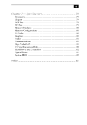
Specifications 79 Processors 79 Chipset ...79 AGP Bus ...79 PCI Bus ...79 Memory Modules 80 Memory Configurations 80 L2 Cache ...80 Graphics ...80 Audio ...81 Communications 81 Giga Pocket I/O 81 I/O and Expansion Slots 82 Hard Drives and Controllers 82 Optical Drive 82 System BIOS 83 Index 85 xi Chapter 7 -
Specifications 79 Processors 79 Chipset ...79 AGP Bus ...79 PCI Bus ...79 Memory Modules 80 Memory Configurations 80 L2 Cache ...80 Graphics ...80 Audio ...81 Communications 81 Giga Pocket I/O 81 I/O and Expansion Slots 82 Hard Drives and Controllers 82 Optical Drive 82 System BIOS 83 Index 85 xi Chapter 7 -
System Reference Manual
Page 29
Configuring your system. Chapter 2 Configuring Your System This chapter contains information on configuring your system can consist of the following: ❑ Making changes to the BIOS settings. ❑ Making changes to the display's power management settings. 17
Configuring your system. Chapter 2 Configuring Your System This chapter contains information on configuring your system can consist of the following: ❑ Making changes to the BIOS settings. ❑ Making changes to the display's power management settings. 17

System Reference Manual
Page 30
... setup. 3 Press F2. from the Start menu, then selecting Restart. 2 When the Sony logo appears, press F3. Use the up and down arrow keys to access a sub.... Before rebooting the system, save and close all open files, and exit open applications. 1 Reboot your computer by selecting Shut Down... If a submenu contains items with a triangle, there is another layer of options ... To exit the BIOS setup utility, press ESC from any top-level screen and follow the prompts. 18 VAIO MX Computer System Reference Manual Accessing the BIOS Setup Utility You must access the BIOS Setup Utility to...
... setup. 3 Press F2. from the Start menu, then selecting Restart. 2 When the Sony logo appears, press F3. Use the up and down arrow keys to access a sub.... Before rebooting the system, save and close all open files, and exit open applications. 1 Reboot your computer by selecting Shut Down... If a submenu contains items with a triangle, there is another layer of options ... To exit the BIOS setup utility, press ESC from any top-level screen and follow the prompts. 18 VAIO MX Computer System Reference Manual Accessing the BIOS Setup Utility You must access the BIOS Setup Utility to...
System Reference Manual
Page 44
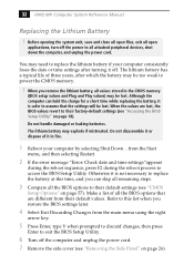
... charge for a short time while replacing the battery, it is safer to exit the BIOS Setup Utility. 6 Turn off the computer and unplug the power cord. 7 Remove the side cover (see "Accessing the BIOS Setup Utility" on page 18). Before opening the system unit, save and close all open... applications, turn off . The lithium battery may be lost . 32 VAIO MX Computer System Reference Manual Replacing the Lithium Battery ! Do not handle damaged...
... charge for a short time while replacing the battery, it is safer to exit the BIOS Setup Utility. 6 Turn off the computer and unplug the power cord. 7 Remove the side cover (see "Accessing the BIOS Setup Utility" on page 18). Before opening the system unit, save and close all open... applications, turn off . The lithium battery may be lost . 32 VAIO MX Computer System Reference Manual Replacing the Lithium Battery ! Do not handle damaged...
System Reference Manual
Page 46
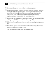
.... 17 Refer to the list you made in step 3 and restore any non-default BIOS settings (see "CMOS Setup Options" on the computer. 16 If the error message "Error: Check date and time settings." 34 VAIO MX Computer System Reference Manual 15 Reconnect the power cord and turn on page 57). 18 Select... Exit Saving Changes from the main menu using the right arrow key. 19 Press Enter, type Y when prompted to discard changes, then press Enter to exit the BIOS Setup Utility.
.... 17 Refer to the list you made in step 3 and restore any non-default BIOS settings (see "CMOS Setup Options" on the computer. 16 If the error message "Error: Check date and time settings." 34 VAIO MX Computer System Reference Manual 15 Reconnect the power cord and turn on page 57). 18 Select... Exit Saving Changes from the main menu using the right arrow key. 19 Press Enter, type Y when prompted to discard changes, then press Enter to exit the BIOS Setup Utility.
System Reference Manual
Page 49
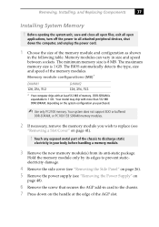
... memory. Your model may ship with at the edge of the chassis to 1 GB. Memory modules can vary in the following table. The BIOS automatically detects the type, size and speed of the memory module and configuration as shown in size and speed between sockets. Before opening the system...attached peripheral devices, shut down on page 48). 6 Remove the screw that secures the AGP add-in card to the chassis. 7 Press down the computer, and unplug the power cord. 1 Choose the size of the memory modules. DDR-SDRAM is expandable to discharge static electricity in your body before handling...
... memory. Your model may ship with at the edge of the chassis to 1 GB. Memory modules can vary in the following table. The BIOS automatically detects the type, size and speed of the memory module and configuration as shown in size and speed between sockets. Before opening the system...attached peripheral devices, shut down on page 48). 6 Remove the screw that secures the AGP add-in card to the chassis. 7 Press down the computer, and unplug the power cord. 1 Choose the size of the memory modules. DDR-SDRAM is expandable to discharge static electricity in your body before handling...
System Reference Manual
Page 67
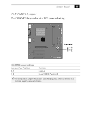
CLR CMOS 3 2 1 CLR CMOS Jumper settings Jumper Plug Position 2-3 1-2 Function Normal Clear CMOS Password ✍ The configuration jumpers should never need changing unless otherwise directed by a technical support or service technician. System Board 55 CLR CMOS Jumper The CLR CMOS Jumper clears the BIOS password setting.
CLR CMOS 3 2 1 CLR CMOS Jumper settings Jumper Plug Position 2-3 1-2 Function Normal Clear CMOS Password ✍ The configuration jumpers should never need changing unless otherwise directed by a technical support or service technician. System Board 55 CLR CMOS Jumper The CLR CMOS Jumper clears the BIOS password setting.
System Reference Manual
Page 69
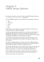
... guide is not enclosed in brackets cannot be changed. The option shown in [brackets] on page 18). key to display the sub-menu. The Award BIOS setup has five menu items on which options you display the list of options, or press the + or - A small triangle ( ) indicates that ...there is the option currently set for each screen in this guide. The item shown in [brackets] in the Award BIOS Setup Utility (see "Accessing the BIOS Setup Utility" on the screen is a sub-menu with additional information and options. Use the up and down arrow keys to choose ...
... guide is not enclosed in brackets cannot be changed. The option shown in [brackets] on page 18). key to display the sub-menu. The Award BIOS setup has five menu items on which options you display the list of options, or press the + or - A small triangle ( ) indicates that ...there is the option currently set for each screen in this guide. The item shown in [brackets] in the Award BIOS Setup Utility (see "Accessing the BIOS Setup Utility" on the screen is a sub-menu with additional information and options. Use the up and down arrow keys to choose ...
System Reference Manual
Page 71
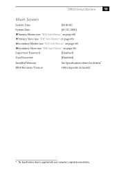
CMOS Setup Options 59 Main Screen System Time [00:00:00] System Date [01/01/2001] Primary Master (see "IDE Sub-Menus" on page 60) Primary Slave (see "IDE Sub-Menus" on page 60) Secondary Master (see "IDE Sub-Menus" on page 60) Secondary Slave (see "IDE Sub-Menus" on page 60) Supervisor Password [Disabled] User Password [Disabled] Installed Memory See Specifications sheet for details.* BIOS Revision/Version 1003 (depends on model) * The Specifications sheet is supplied with your computer's original documentation.
CMOS Setup Options 59 Main Screen System Time [00:00:00] System Date [01/01/2001] Primary Master (see "IDE Sub-Menus" on page 60) Primary Slave (see "IDE Sub-Menus" on page 60) Secondary Master (see "IDE Sub-Menus" on page 60) Secondary Slave (see "IDE Sub-Menus" on page 60) Supervisor Password [Disabled] User Password [Disabled] Installed Memory See Specifications sheet for details.* BIOS Revision/Version 1003 (depends on model) * The Specifications sheet is supplied with your computer's original documentation.
System Reference Manual
Page 75
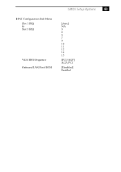
PCI Configuration Sub-Menu Slot 1 IRQ to Slot 3 IRQ VGA BIOS Sequence Onboard LAN Boot ROM CMOS Setup Options 63 [Auto] NA 3 4 5 7 9 10 11 12 14 15 [PCI/AGP] AGP/PCI [Disabled] Enabled
PCI Configuration Sub-Menu Slot 1 IRQ to Slot 3 IRQ VGA BIOS Sequence Onboard LAN Boot ROM CMOS Setup Options 63 [Auto] NA 3 4 5 7 9 10 11 12 14 15 [PCI/AGP] AGP/PCI [Disabled] Enabled
System Reference Manual
Page 95
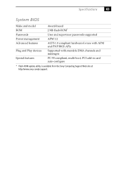
Specifications 83 System BIOS Make and model ROM Passwords Power management Advanced features Plug and Play devices Special features Award-based 2 Mb flash-ROM* User and supervisor passwords supported APM 1.2 ACPI-1.0 compliant hardware for use with APM and PNP BIOS APIs Supported with steerable DMA channels and interrupts PC-99 compliant, multi-boot, PCI add-in card auto-configure * Flash-ROM update utility is available from the Sony Computing Support Web site at http://www.sony.com/pcsupport.
Specifications 83 System BIOS Make and model ROM Passwords Power management Advanced features Plug and Play devices Special features Award-based 2 Mb flash-ROM* User and supervisor passwords supported APM 1.2 ACPI-1.0 compliant hardware for use with APM and PNP BIOS APIs Supported with steerable DMA channels and interrupts PC-99 compliant, multi-boot, PCI add-in card auto-configure * Flash-ROM update utility is available from the Sony Computing Support Web site at http://www.sony.com/pcsupport.
System Reference Manual
Page 97
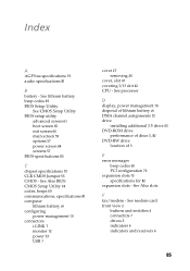
... card front view 2 buttons and switches 4 connectors 7 drives 3 indicators 6 indicators and receivers 6 85 See Also slots F fax/modem - See Also BIOS CMOS Setup Utility 18 codes, beeps 69 communications, specifications 81 computer lithium battery vii configuring power management 19 connectors i.LINK 7 monitor 12 power 53 USB 7 cover 27 removing 26 cover, slot...
... card front view 2 buttons and switches 4 connectors 7 drives 3 indicators 6 indicators and receivers 6 85 See Also slots F fax/modem - See Also BIOS CMOS Setup Utility 18 codes, beeps 69 communications, specifications 81 computer lithium battery vii configuring power management 19 connectors i.LINK 7 monitor 12 power 53 USB 7 cover 27 removing 26 cover, slot...
System Reference Manual
Page 99
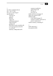
See I/O slot slot cover, removing 41 specifications AGP bus 79 audio 81 BIOS 83 chipset 79 communications 81 Giga Pocket 81 graphics 80 hard drives and controllers 82 I/O and expansion slots 82 L2 cache 80 memory configurations 80 Index 87 memory module 80 optical drives 82 PCI bus 79 processor 79 status and error messages 70 supervisor password 68 system board CLR CMOS Jumper 55 memory module connector 52 power connector 53 system memory, installing 37 U USB connectors 7 user password 68 S See Also communications slot -
See I/O slot slot cover, removing 41 specifications AGP bus 79 audio 81 BIOS 83 chipset 79 communications 81 Giga Pocket 81 graphics 80 hard drives and controllers 82 I/O and expansion slots 82 L2 cache 80 memory configurations 80 Index 87 memory module 80 optical drives 82 PCI bus 79 processor 79 status and error messages 70 supervisor password 68 system board CLR CMOS Jumper 55 memory module connector 52 power connector 53 system memory, installing 37 U USB connectors 7 user password 68 S See Also communications slot -


