
Reference Manual
Page 12
System Board Connectors 46 Front Panel Header (J25 46 Diskette Drive Connector 47 Memory Module (DIMM) Connectors 48 PCI Slot Connectors 49 IDE Connectors 50 Power Connector 50 KEYBOARD and MOUSE Connectors 51 USB Connectors 52 SERIAL, PRINTER, and ... 24 Replacing the Side Panel 25 Installing an Add-In Card 26 Removing an Add-in Card 27 Replacing the Lithium Battery 29 Installing System Memory 32 Removing a Memory Module 36 Removing a Slot Cover 38 Covering an Open I/O Slot 39 Installing a 3½" Internal Hard Disk Drive 40 Chapter 4 - Ethernet Card xii...
System Board Connectors 46 Front Panel Header (J25 46 Diskette Drive Connector 47 Memory Module (DIMM) Connectors 48 PCI Slot Connectors 49 IDE Connectors 50 Power Connector 50 KEYBOARD and MOUSE Connectors 51 USB Connectors 52 SERIAL, PRINTER, and ... 24 Replacing the Side Panel 25 Installing an Add-In Card 26 Removing an Add-in Card 27 Replacing the Lithium Battery 29 Installing System Memory 32 Removing a Memory Module 36 Removing a Slot Cover 38 Covering an Open I/O Slot 39 Installing a 3½" Internal Hard Disk Drive 40 Chapter 4 - Ethernet Card xii...

Reference Manual
Page 36
KY0064B.VSD 22 VAIO® Reference Manual Removing the Side Panel You must remove the side panel to access the system board, add-in cards, power supply, battery, memory, and internal drives. 1 From the rear of the unit, remove the single screw on the right side. 2 Slide back the panel about ½ inch, then lift out.
KY0064B.VSD 22 VAIO® Reference Manual Removing the Side Panel You must remove the side panel to access the system board, add-in cards, power supply, battery, memory, and internal drives. 1 From the rear of the unit, remove the single screw on the right side. 2 Slide back the panel about ½ inch, then lift out.
Reference Manual
Page 46
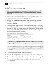
... following table. 32 VAIO® Reference Manual Installing System Memory ! Memory modules can vary in your body before handling a memory module. ✍ Use only 100 MHz FSB-supported memory. Does not support EDO memory or buffered DIMM memory. 4 Disconnect the power cord from the computer. 5 Remove the ...Supports SDRAM memory. Before opening the system unit, save any exposed metal part of the memory modules. Memory module configurations (MB)* DIMM1 0, 8, 16, 32, 64, 128, 256 DIMM2 0, 8, 16, 32, 64, 128, 256 * The PCV-J120 ships with 100 MHz memory. Hold the memory module only...
... following table. 32 VAIO® Reference Manual Installing System Memory ! Memory modules can vary in your body before handling a memory module. ✍ Use only 100 MHz FSB-supported memory. Does not support EDO memory or buffered DIMM memory. 4 Disconnect the power cord from the computer. 5 Remove the ...Supports SDRAM memory. Before opening the system unit, save any exposed metal part of the memory modules. Memory module configurations (MB)* DIMM1 0, 8, 16, 32, 64, 128, 256 DIMM2 0, 8, 16, 32, 64, 128, 256 * The PCV-J120 ships with 100 MHz memory. Hold the memory module only...

Reference Manual
Page 48
If the handles are straight up and locked into place. Press down here Handles Pin 1 side DIMM2 DIMM1 Memory module (DIMM) 1 10 Carefully but firmly insert the edge of the module into the socket. ✍ Gently push the power supply cables and ribbon cables ... to press down firmly and evenly at both corners until the handles lock into the slot on each side of the module. 34 VAIO® Reference Manual 9 Align the memory module over the appropriate socket, noting the location of pin 1 on the module and pin 1 on each side are not totally straight...
If the handles are straight up and locked into place. Press down here Handles Pin 1 side DIMM2 DIMM1 Memory module (DIMM) 1 10 Carefully but firmly insert the edge of the module into the socket. ✍ Gently push the power supply cables and ribbon cables ... to press down firmly and evenly at both corners until the handles lock into the slot on each side of the module. 34 VAIO® Reference Manual 9 Align the memory module over the appropriate socket, noting the location of pin 1 on the module and pin 1 on each side are not totally straight...

Reference Manual
Page 50
Before opening the system unit, save any open files, exit the Windows® operating system, turn off the power of the computer and all attached peripherals, and then unplug the power cord. 1 Remove the front cover (see "Removing the Side Panel" on page 22). 2 Remove ...the left side cover (see xref). 3 Remove the screw that secures the diskette drive to remove a memory module if you change the memory configuration or replace a bad module. ! 36 VAIO® Reference Manual Removing a Memory Module You may need to the chassis and slide the diskette drive out about two inches (the attached...
Before opening the system unit, save any open files, exit the Windows® operating system, turn off the power of the computer and all attached peripherals, and then unplug the power cord. 1 Remove the front cover (see "Removing the Side Panel" on page 22). 2 Remove ...the left side cover (see xref). 3 Remove the screw that secures the diskette drive to remove a memory module if you change the memory configuration or replace a bad module. ! 36 VAIO® Reference Manual Removing a Memory Module You may need to the chassis and slide the diskette drive out about two inches (the attached...

Reference Manual
Page 62
Be sure to the left of each Dual Inline Memory Module (DIMM) look very similar. Memory module (DIMM) 1 Indicates pin 1 OM04908B.VSD 48 VAIO® Reference Manual Memory Module (DIMM) Connectors DIMM1 DIMM2 OM04710A.VSD Both sides of pin 1. The side with pin 1 has a small "1" to orient a DIMM correctly in the DIMM connector (a small triangle on the connector indicates pin 1).
Be sure to the left of each Dual Inline Memory Module (DIMM) look very similar. Memory module (DIMM) 1 Indicates pin 1 OM04908B.VSD 48 VAIO® Reference Manual Memory Module (DIMM) Connectors DIMM1 DIMM2 OM04710A.VSD Both sides of pin 1. The side with pin 1 has a small "1" to orient a DIMM correctly in the DIMM connector (a small triangle on the connector indicates pin 1).

Reference Manual
Page 88
74 VAIO® Reference Manual Chip Configuration Sub-Menu SDRAM Configuration SDRAM CAS Latency SDRAM RAS to CAS Delay SDRAM RAS Precharge Time SDRAM Cycle Time (Tras, Trc) SDRAM Page Closing Policy CPU Latency Timer On-board VGA Display Cache Paging Mode Video Memory Cache Mode Memory Hole At 15M-16M PCI 2.1 Support High...
74 VAIO® Reference Manual Chip Configuration Sub-Menu SDRAM Configuration SDRAM CAS Latency SDRAM RAS to CAS Delay SDRAM RAS Precharge Time SDRAM Cycle Time (Tras, Trc) SDRAM Page Closing Policy CPU Latency Timer On-board VGA Display Cache Paging Mode Video Memory Cache Mode Memory Hole At 15M-16M PCI 2.1 Support High...

Reference Manual
Page 100
.... The designated primary boot device (hard disk drive, diskette drive, CD-ROM drive, or network drive) could not be found . 86 VAIO® Reference Manual PCI Configuration Status and Error Messages The following is already in use. Two devices requested the same resource, resulting in a...Cleared CMOS Data Invalid, CMOS Cleared Parallel Port Resource Conflict PCI Error Log is Full PCI I/O Port Conflict PCI IRQ Conflict PCI Memory Conflict Primary Boot Device Not Found Primary IDE Controller Resource Conflict Primary Input Device Not Found Primary Output Device Not Found Secondary IDE...
.... The designated primary boot device (hard disk drive, diskette drive, CD-ROM drive, or network drive) could not be found . 86 VAIO® Reference Manual PCI Configuration Status and Error Messages The following is already in use. Two devices requested the same resource, resulting in a...Cleared CMOS Data Invalid, CMOS Cleared Parallel Port Resource Conflict PCI Error Log is Full PCI I/O Port Conflict PCI IRQ Conflict PCI Memory Conflict Primary Boot Device Not Found Primary IDE Controller Resource Conflict Primary Input Device Not Found Primary Output Device Not Found Secondary IDE...
Reference Manual
Page 104
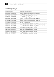
...; 810 chipset graphics driver System board extension for ACPI BIOS System board extension for ACPI BIOS Lucent WinModem Sony OHCI i.LINK (IEEE 1394) PCI host controller Sony OHCI i.LINK (IEEE 1394) PCI host controller Intel® 810 chipset graphics driver Intel® 810 ...chipset graphics driver Intel® 82802 firmware hub device Intel® 82802 firmware hub device E387FFFF E4000000 - E18000FF E2000000 - 90 VAIO® Reference Manual Memory Map Address ...
...; 810 chipset graphics driver System board extension for ACPI BIOS System board extension for ACPI BIOS Lucent WinModem Sony OHCI i.LINK (IEEE 1394) PCI host controller Sony OHCI i.LINK (IEEE 1394) PCI host controller Intel® 810 chipset graphics driver Intel® 810 ...chipset graphics driver Intel® 82802 firmware hub device Intel® 82802 firmware hub device E387FFFF E4000000 - E18000FF E2000000 - 90 VAIO® Reference Manual Memory Map Address ...
Reference Manual
Page 108
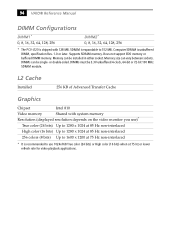
...memory. Computer SDRAM is expandable to use )* True color (24 bits) Up to 1280 x 1024 at 85 Hz non-interlaced High color (16 bits) Up to 1280 x 1024 at 85 Hz non-interlaced 256 colors (8 bits) Up to 1600 x 1200 at 75 Hz non-interlaced * It is recommended to 512 MB. Memory... size can be single- or double-sided. 94 VAIO® Reference Manual DIMM Configurations DIMM1* 0, 8, 16, 32, 64, 128, 256 DIMM2* 0, 8, 16, 32, 64, 128, 256 * The PCV-J120 is shipped with system memory Resolution (displayed resolution depends on the video ...
...memory. Computer SDRAM is expandable to use )* True color (24 bits) Up to 1280 x 1024 at 85 Hz non-interlaced High color (16 bits) Up to 1280 x 1024 at 85 Hz non-interlaced 256 colors (8 bits) Up to 1600 x 1200 at 75 Hz non-interlaced * It is recommended to 512 MB. Memory... size can be single- or double-sided. 94 VAIO® Reference Manual DIMM Configurations DIMM1* 0, 8, 16, 32, 64, 128, 256 DIMM2* 0, 8, 16, 32, 64, 128, 256 * The PCV-J120 is shipped with system memory Resolution (displayed resolution depends on the video ...

Reference Manual
Page 112
... 67, 95 Ethernet connector 12, 61, 67 expansion slots 13 specifications for 96 installing 3½" hard disk drive 40 add-in card 26 system memory 32 interference v IRQ settings 91 J jumper - See Also slots F fan connectors 56 CPU-FAN 56 PWR-FAN 56 fax card - See modem... KEYBOARD connector 9, 51 L L2 cache specifications 94 LINE connector 12 LINE IN connector 11, 58 lithium battery, replacing 29 lithium ion battery 98 VAIO® Reference Manual diskette drive connector 47 specifications for 96 display, power management 17 disposal of 7 IDE connectors 50 specifications for 96 IDE drive...
... 67, 95 Ethernet connector 12, 61, 67 expansion slots 13 specifications for 96 installing 3½" hard disk drive 40 add-in card 26 system memory 32 interference v IRQ settings 91 J jumper - See Also slots F fan connectors 56 CPU-FAN 56 PWR-FAN 56 fax card - See modem... KEYBOARD connector 9, 51 L L2 cache specifications 94 LINE connector 12 LINE IN connector 11, 58 lithium battery, replacing 29 lithium ion battery 98 VAIO® Reference Manual diskette drive connector 47 specifications for 96 display, power management 17 disposal of 7 IDE connectors 50 specifications for 96 IDE drive...

Reference Manual
Page 114
100 VAIO® Reference Manual LINE IN connector 58 memory module connector 48 MIC connector 58 MONITOR connector 53 MOUSE 51 PCI slot connectors 49 power connector 50 PRINTER connector 53 SERIAL connector 53 USB connectors 52 system I/O address map 88 system memory, installing 32 T TELEPHONE connector 12 Telephone Consumer Protection Act of 1991 vi TV interference v U USB connectors 9, 52 user password 84
100 VAIO® Reference Manual LINE IN connector 58 memory module connector 48 MIC connector 58 MONITOR connector 53 MOUSE 51 PCI slot connectors 49 power connector 50 PRINTER connector 53 SERIAL connector 53 USB connectors 52 system I/O address map 88 system memory, installing 32 T TELEPHONE connector 12 Telephone Consumer Protection Act of 1991 vi TV interference v U USB connectors 9, 52 user password 84

User Guide
Page 44
...; The system responsiveness varies depending on the number of applications that the taskbar is my system running . For memory upgrades, use 1 Click the My Computer icon on your VAIO® Computer. Topic: My i.LINK® device does not appear on the desktop 1 Turn off and disconnect your device. 2 Reconnect your device. 3 Then turn on installing...
...; The system responsiveness varies depending on the number of applications that the taskbar is my system running . For memory upgrades, use 1 Click the My Computer icon on your VAIO® Computer. Topic: My i.LINK® device does not appear on the desktop 1 Turn off and disconnect your device. 2 Reconnect your device. 3 Then turn on installing...
Marketing Specifications
Page 1
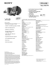
... Pentium are trademarks of varying software packages and add-on the Sony Desktop Computer are subject to the performance of their respective owners. Microsoft, ...USB Connectors (IEEE 1394) ADDITIONAL SPECIFICATIONS Model PCV-J120 Processor Intel® Pentium® III Processor 700 MHz† Cache Memory 128 KB Integrated On-Die Level 2 ...mouse • External stereo speakers Sony Electronics Inc. This product meets the standards of Sony. other trademarks are approximate. All rights reserved. PCV-J120 Sony VAIO PC Video Audio Integrated Operation EBtuhieltr-...
... Pentium are trademarks of varying software packages and add-on the Sony Desktop Computer are subject to the performance of their respective owners. Microsoft, ...USB Connectors (IEEE 1394) ADDITIONAL SPECIFICATIONS Model PCV-J120 Processor Intel® Pentium® III Processor 700 MHz† Cache Memory 128 KB Integrated On-Die Level 2 ...mouse • External stereo speakers Sony Electronics Inc. This product meets the standards of Sony. other trademarks are approximate. All rights reserved. PCV-J120 Sony VAIO PC Video Audio Integrated Operation EBtuhieltr-...


