
Product Brochure (v2222)
Page 7
..., AES/EBU, 48 kHz fixed, complies with AES-3id-1995 D-sub 9-pin (x2), Sony 9-pin remote interface D-sub 9-pin (x1), RS-232C interface D-sub 50-pin (x1)...selectable) T1=50 µs, T2=15 µs PSW 4x16 Rack mount screw (x4), Operation manual (x1), Installation manual (x1) *ISR: Interactive Status Reporting 7 SPECIFICATIONS General Power requirements Power consumption Operating temperature Storage... Analog input to analog output Head room Emphasis (ON/OFF selectable in REC mode) Supplied accessories DVW-M2000/M2000P DVW-2000/2000P AC 100 V to 240 V, 50/60 Hz 220 W +5 ˚C to...
..., AES/EBU, 48 kHz fixed, complies with AES-3id-1995 D-sub 9-pin (x2), Sony 9-pin remote interface D-sub 9-pin (x1), RS-232C interface D-sub 50-pin (x1)...selectable) T1=50 µs, T2=15 µs PSW 4x16 Rack mount screw (x4), Operation manual (x1), Installation manual (x1) *ISR: Interactive Status Reporting 7 SPECIFICATIONS General Power requirements Power consumption Operating temperature Storage... Analog input to analog output Head room Emphasis (ON/OFF selectable in REC mode) Supplied accessories DVW-M2000/M2000P DVW-2000/2000P AC 100 V to 240 V, 50/60 Hz 220 W +5 ˚C to...
Product Manual (Operation Manual 1st Edition (Revised 6))
Page 10
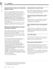
...user bits. DVW2000/2000P: (4 channels)) • AES/EBU serial digital audio input (4 channels) • AES/EBU serial digital audio output (DVW-M2000/ M2000P: 8 channels; DVW-2000/2000P: 4 channels) • Time code input/output • Cue audio signal input/output High quality four-channel audio High quality 20 ...shows not only various values and settings, but also the pages of recorded resources to be set from the control panel by this manual. 1) High-precision digital signal processing and range of interfaces While supporting a wide range of input and output signals, all of connection...
...user bits. DVW2000/2000P: (4 channels)) • AES/EBU serial digital audio input (4 channels) • AES/EBU serial digital audio output (DVW-M2000/ M2000P: 8 channels; DVW-2000/2000P: 4 channels) • Time code input/output • Cue audio signal input/output High quality four-channel audio High quality 20 ...shows not only various values and settings, but also the pages of recorded resources to be set from the control panel by this manual. 1) High-precision digital signal processing and range of interfaces While supporting a wide range of input and output signals, all of connection...
Product Manual (Operation Manual 1st Edition (Revised 6))
Page 111
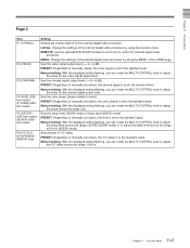
...177;30 IRE (525/60 mode) or to +3 dB). Sets the setup level (525/60 mode) or black level (625/50 mode) PRESET: Regardless of manually set values, the color phase is set to the standard level. Chapter 11 Function Menu Page 2 Item F1 (V.PROC) F2 (VIDEO) F3 (CHROMA) F4 (...HUE) (525line mode)/ (C PHAS) (625line mode) F5 (SETUP) (525-line mode)/ (BLACK) (625line mode) F6 (YC DLY) (DVW-M2000/ M2000P only) Setting Selects the control method for the video signal output level. Sets the chroma signal output level (-∞ to adjust the black level across...
...177;30 IRE (525/60 mode) or to +3 dB). Sets the setup level (525/60 mode) or black level (625/50 mode) PRESET: Regardless of manually set values, the color phase is set to the standard level. Chapter 11 Function Menu Page 2 Item F1 (V.PROC) F2 (VIDEO) F3 (CHROMA) F4 (...HUE) (525line mode)/ (C PHAS) (625line mode) F5 (SETUP) (525-line mode)/ (BLACK) (625line mode) F6 (YC DLY) (DVW-M2000/ M2000P only) Setting Selects the control method for the video signal output level. Sets the chroma signal output level (-∞ to adjust the black level across...
Product Manual (Operation Manual 1st Edition (Revised 6))
Page 125
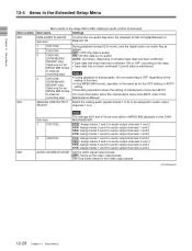
...menu screen. OFF : Do not open the Tele-File menu automatically when a cassette with the control panel of the VTRs. 202 CF FLAG (DVW-M2000P/ Select the mode for data modification operations in the Tele-File menu. IN: Only the IN connector is effective whether in local or remote ...NOT CLEAR : Do not clear the thread counter. ON: Open the Tele-File menu automatically. 135 TELE-FILE THREAD Selects whether to the Maintenance Manual Volume 1. 12-11 Chapter 12 Setup Menus DIS : No synchronized operation ENA: Use synchronized operation Note To use synchronized operation for two or ...
...menu screen. OFF : Do not open the Tele-File menu automatically when a cassette with the control panel of the VTRs. 202 CF FLAG (DVW-M2000P/ Select the mode for data modification operations in the Tele-File menu. IN: Only the IN connector is effective whether in local or remote ...NOT CLEAR : Do not clear the thread counter. ON: Open the Tele-File menu automatically. 135 TELE-FILE THREAD Selects whether to the Maintenance Manual Volume 1. 12-11 Chapter 12 Setup Menus DIS : No synchronized operation ENA: Use synchronized operation Note To use synchronized operation for two or ...
Product Manual (Operation Manual 1st Edition (Revised 6))
Page 142
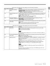
...One frame ahead of maintenance menu item M372. 8-channel For more information about the maintenance menu item M372, refer to the recording tape Maintenance Manual. 824 ANALOG LINE OUTPUT Select the analog audio signals (tracks 1 to 8) to be assigned to audio output SELECT channels 1 to audio...) Item number Item name Settings 823 NON-AUDIO FLAG PB Controls the non-audio flag when the playback format is non-audio) (DVW-M2000/ AUTO: As follows, depending on the DVWM2000/M2000P. 1 CH1/CH2 tr1/2 : Assign tracks 1 and 2 to audio output channels 1 and 2 tr3/4: Assign tracks 3 and 4...
...One frame ahead of maintenance menu item M372. 8-channel For more information about the maintenance menu item M372, refer to the recording tape Maintenance Manual. 824 ANALOG LINE OUTPUT Select the analog audio signals (tracks 1 to 8) to be assigned to audio output SELECT channels 1 to audio...) Item number Item name Settings 823 NON-AUDIO FLAG PB Controls the non-audio flag when the playback format is non-audio) (DVW-M2000/ AUTO: As follows, depending on the DVWM2000/M2000P. 1 CH1/CH2 tr1/2 : Assign tracks 1 and 2 to audio output channels 1 and 2 tr3/4: Assign tracks 3 and 4...
Product Manual (dvwm2000 installation manual)
Page 3
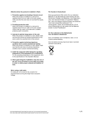
...temperature of this product is provided with a suitable protective earth connection. 3. HDW-2000/M2000/M2000P/S2000/S2000P/M2100/M2100P, DVW-2000/2000P/M2000/M2000P MSW-2000/A2000/A2000P/M2000/M2000P/M2000E/M2000EP/M2100/M2100P/M2100E/M2100EP 1 (P) Internal air ambient temperature of the rack When ... verwijderen, leest u in a rack, please make sure that might have excessive voltage. Prevention against overloading of the Operation Manual. 6. Attention-when the product is installed in de Onderhoudshandleiding. When using a LAN cable: For safety,do not connect to uneven mechanical ...
...temperature of this product is provided with a suitable protective earth connection. 3. HDW-2000/M2000/M2000P/S2000/S2000P/M2100/M2100P, DVW-2000/2000P/M2000/M2000P MSW-2000/A2000/A2000P/M2000/M2000P/M2000E/M2000EP/M2100/M2100P/M2100E/M2100EP 1 (P) Internal air ambient temperature of the rack When ... verwijderen, leest u in a rack, please make sure that might have excessive voltage. Prevention against overloading of the Operation Manual. 6. Attention-when the product is installed in de Onderhoudshandleiding. When using a LAN cable: For safety,do not connect to uneven mechanical ...
Product Manual (dvwm2000 installation manual)
Page 5
.../Reattaching Plug-in Tape Slacking 1-30 Appendix A Setting Check Sheet HDW-2000/M2000/M2000P/S2000/S2000P/M2100/M2100P, DVW-2000/2000P/M2000/M2000P 1 MSW-2000/A2000/A2000P/M2000/M2000P/M2000E/M2000EP/M2100/M2100P/M2100E/M2100EP Rack Mounting 1-4 1-7. VTR Constant Values Settings of... Switching Search Dial Mode 1-24 1-14. System Phase Alignment 1-28 1-15-4. Table of Contents Manual Structure Purpose of this manual 2 Related manuals ...2 1. Installation Procedure 1-1 1-2. Switch Settings on Connector Panel 1-15 1-10. Matching Connectors and Cables 1-9 1-8.
.../Reattaching Plug-in Tape Slacking 1-30 Appendix A Setting Check Sheet HDW-2000/M2000/M2000P/S2000/S2000P/M2100/M2100P, DVW-2000/2000P/M2000/M2000P 1 MSW-2000/A2000/A2000P/M2000/M2000P/M2000E/M2000EP/M2100/M2100P/M2100E/M2100EP Rack Mounting 1-4 1-7. VTR Constant Values Settings of... Switching Search Dial Mode 1-24 1-14. System Phase Alignment 1-28 1-15-4. Table of Contents Manual Structure Purpose of this manual 2 Related manuals ...2 1. Installation Procedure 1-1 1-2. Switch Settings on Connector Panel 1-15 1-10. Matching Connectors and Cables 1-9 1-8.
Product Manual (dvwm2000 installation manual)
Page 6
... HDW-2000/M2000/M2000P/S2000/S2000P/M2100/M2100P, DVW-2000/2000P/M2000/M2000P MSW-2000/A2000/A2000P/M2000/M2000P/M2000E/M2000EP/M2100/M2100P/M2100E/M2100EP Maintenance Manual (Available on request) This manual explains the protocol for the corresponding unit. Semiconductors that is the installation manual of the following manuals are required, please contact your local Sony Sales Office/Service...
... HDW-2000/M2000/M2000P/S2000/S2000P/M2100/M2100P, DVW-2000/2000P/M2000/M2000P MSW-2000/A2000/A2000P/M2000/M2000P/M2000E/M2000EP/M2100/M2100P/M2100E/M2100EP Maintenance Manual (Available on request) This manual explains the protocol for the corresponding unit. Semiconductors that is the installation manual of the following manuals are required, please contact your local Sony Sales Office/Service...
Product Manual (dvwm2000 installation manual)
Page 7
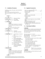
... is operat- Installation Space".) . HDW-2000/M2000/M2000P/S2000/S2000P/M2100/M2100P, DVW-2000/2000P/M2000/M2000P MSW-2000/A2000/A2000P/M2000/M2000P/M2000E/M2000EP/M2100/M2100P/M2100E/M2100EP 1-1 Installation Procedure 1-2. Power Supply 1-5. Operation manual Japanese *1 1 English 1 . Operation manual & application software CD-ROM (PDF)*2 1 . BKMW-E3000 Installation manual*2 1 *1: Supplied with DVW series only. *2: Supplied with sufficient air circulation...
... is operat- Installation Space".) . HDW-2000/M2000/M2000P/S2000/S2000P/M2100/M2100P, DVW-2000/2000P/M2000/M2000P MSW-2000/A2000/A2000P/M2000/M2000P/M2000E/M2000EP/M2100/M2100P/M2100E/M2100EP 1-1 Installation Procedure 1-2. Power Supply 1-5. Operation manual Japanese *1 1 English 1 . Operation manual & application software CD-ROM (PDF)*2 1 . BKMW-E3000 Installation manual*2 1 *1: Supplied with DVW series only. *2: Supplied with sufficient air circulation...
Product Manual (dvwm2000 installation manual)
Page 17
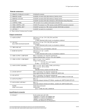
... for a TBC remote controller (HKDV-900) connection 4 (OPTION) *4, 5 D-SUB 9P connector for an optional kit *** : Refer to Optional "Interface manual" for character superimpose) Serial digital interface (270 Mbit/s), complies with SMPTE 259M & ITU-R BT.656 BNC x 2 Serial data transport interface (270 Mbit/s),... Serial digital interface (270 Mbit/s), complies with IEEE802.3i) (Automatically detected by Auto-Negotiation) HDW-2000/M2000/M2000P/S2000/S2000P/M2100/M2100P, DVW-2000/2000P/M2000/M2000P MSW-2000/A2000/A2000P/M2000/M2000P/M2000E/M2000EP/M2100/M2100P/M2100E/M2100EP 1-11 1-8.
... for a TBC remote controller (HKDV-900) connection 4 (OPTION) *4, 5 D-SUB 9P connector for an optional kit *** : Refer to Optional "Interface manual" for character superimpose) Serial digital interface (270 Mbit/s), complies with SMPTE 259M & ITU-R BT.656 BNC x 2 Serial data transport interface (270 Mbit/s),... Serial digital interface (270 Mbit/s), complies with IEEE802.3i) (Automatically detected by Auto-Negotiation) HDW-2000/M2000/M2000P/S2000/S2000P/M2100/M2100P, DVW-2000/2000P/M2000/M2000P MSW-2000/A2000/A2000P/M2000/M2000P/M2000E/M2000EP/M2100/M2100P/M2100E/M2100EP 1-11 1-8.
Product Manual (dvwm2000 installation manual)
Page 20
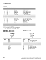
...9 69 Signal DCD ; Transmitted Data (Output) DTR ; Request to Send (Input) NC 1-14 HDW-2000/M2000/M2000P/S2000/S2000P/M2100/M2100P, DVW-2000/2000P/M2000/M2000P MSW-2000/A2000/A2000P/M2000/M2000P/M2000E/M2000EP/M2100/M2100P/M2100E/M2100EP Clear to Send (Output) CTS ; Data Carrier Detect (Input) RXD ; Signal ... ; 10 kZ pull up to +5 V (0 V or open) *2: The pins described as O mark are possible to the optional interface manual for changing the setting. 1-8. Received Data (Input) TXD ; Signal Inputs and Outputs (Continued) Pin No. I/O *1 Setting change the setting. Data ...
...9 69 Signal DCD ; Transmitted Data (Output) DTR ; Request to Send (Input) NC 1-14 HDW-2000/M2000/M2000P/S2000/S2000P/M2100/M2100P, DVW-2000/2000P/M2000/M2000P MSW-2000/A2000/A2000P/M2000/M2000P/M2000E/M2000EP/M2100/M2100P/M2100E/M2100EP Clear to Send (Output) CTS ; Data Carrier Detect (Input) RXD ; Signal ... ; 10 kZ pull up to +5 V (0 V or open) *2: The pins described as O mark are possible to the optional interface manual for changing the setting. 1-8. Received Data (Input) TXD ; Signal Inputs and Outputs (Continued) Pin No. I/O *1 Setting change the setting. Data ...
Product Manual (dvwm2000 installation manual)
Page 21
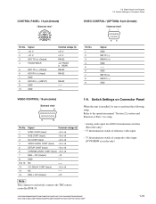
...: 10-pin (female) External view 1 2 3 5 6 8 9 10 Pin No. Refer to the operation manual "Section 2 Location and Function of composite video input (DVW/MSW recorder only) HDW-2000/M2000/M2000P/S2000/S2000P/M2100/M2100P, DVW-2000/2000P/M2000/M2000P MSW-2000/A2000/A2000P/M2000/M2000P/M2000E/M2000EP/M2100/M2100P/M2100E/M2100EP 1-15 Signal Terminal voltage (V) 1 SYNC CONT...
...: 10-pin (female) External view 1 2 3 5 6 8 9 10 Pin No. Refer to the operation manual "Section 2 Location and Function of composite video input (DVW/MSW recorder only) HDW-2000/M2000/M2000P/S2000/S2000P/M2100/M2100P, DVW-2000/2000P/M2000/M2000P MSW-2000/A2000/A2000P/M2000/M2000P/M2000E/M2000EP/M2100/M2100P/M2100E/M2100EP 1-15 Signal Terminal voltage (V) 1 SYNC CONT...
Product Manual (dvwm2000 installation manual)
Page 26
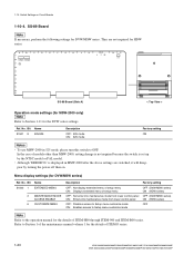
In the case of ITEM-F series. 1-20 HDW-2000/M2000/M2000P/S2000/S2000P/M2100/M2100P, DVW-2000/2000P/M2000/M2000P MSW-2000/A2000/A2000P/M2000/M2000P/M2000E/M2000EP/M2100/M2100P/M2100E/M2100EP Although "ERROR 96" is set up by turning the power off then ...J K SS-89 N P 1 L M S101 S1501 S1502 2A 3 4 5 6 SS-89 Board (Side A) < Top View > Operation mode settings (for MSW-2000 only) n Refer to Section 1 of the maintenance manual volume 1 for the details of models other than MSW-2000, setting change is not required because the switch is displayed in 525 mode, please turn...
In the case of ITEM-F series. 1-20 HDW-2000/M2000/M2000P/S2000/S2000P/M2100/M2100P, DVW-2000/2000P/M2000/M2000P MSW-2000/A2000/A2000P/M2000/M2000P/M2000E/M2000EP/M2100/M2100P/M2100E/M2100EP Although "ERROR 96" is set up by turning the power off then ...J K SS-89 N P 1 L M S101 S1501 S1502 2A 3 4 5 6 SS-89 Board (Side A) < Top View > Operation mode settings (for MSW-2000 only) n Refer to Section 1 of the maintenance manual volume 1 for the details of models other than MSW-2000, setting change is not required because the switch is displayed in 525 mode, please turn...
Product Manual (dvwm2000 installation manual)
Page 27
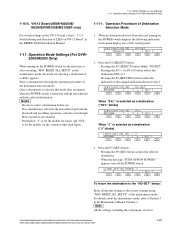
...the maintenance mode, the mode for selecting a destination (J or SYL) appears. Be sure to the original indication shown in the Maintenance Manual Volume-1. If no destination has not been selected, turning on Circuit Boards 1-11. appears, turn off the POWER switch. For details ...DESTINATION SEL - Pressing the F5 (SET) button accepts the selected destination. . HDW-2000/M2000/M2000P/S2000/S2000P/M2100/M2100P, DVW-2000/2000P/M2000/M2000P MSW-2000/A2000/A2000P/M2000/M2000P/M2000E/M2000EP/M2100/M2100P/M2100E/M2100EP 1-21 Switch Setting and Function of the control panel. When no...
...the maintenance mode, the mode for selecting a destination (J or SYL) appears. Be sure to the original indication shown in the Maintenance Manual Volume-1. If no destination has not been selected, turning on Circuit Boards 1-11. appears, turn off the POWER switch. For details ...DESTINATION SEL - Pressing the F5 (SET) button accepts the selected destination. . HDW-2000/M2000/M2000P/S2000/S2000P/M2100/M2100P, DVW-2000/2000P/M2000/M2000P MSW-2000/A2000/A2000P/M2000/M2000P/M2000E/M2000EP/M2100/M2100P/M2100E/M2100EP 1-21 Switch Setting and Function of the control panel. When no...
Product Manual (dvwm2000 installation manual)
Page 28
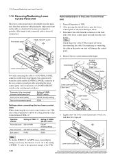
...is about 62 centimeters.) Front switch panel PANEL SELECT switch Cable Lower control panel unit Not only connecting the cable to the operation manual of VTR. 2. Operation enabled Setting of ITEM-117 Setting of PANEL SELECT switch Front-side panel SW or PARA FRONT (Factory setting...the cable in the figure below. 3. 1-12. Lower control panel unit 1-22 HDW-2000/M2000/M2000P/S2000/S2000P/M2100/M2100P, DVW-2000/2000P/M2000/M2000P MSW-2000/A2000/A2000P/M2000/M2000P/M2000E/M2000EP/M2100/M2100P/M2100E/M2100EP Remove the two screws shown in the rear connector panel provides operating ...
...is about 62 centimeters.) Front switch panel PANEL SELECT switch Cable Lower control panel unit Not only connecting the cable to the operation manual of VTR. 2. Operation enabled Setting of ITEM-117 Setting of PANEL SELECT switch Front-side panel SW or PARA FRONT (Factory setting...the cable in the figure below. 3. 1-12. Lower control panel unit 1-22 HDW-2000/M2000/M2000P/S2000/S2000P/M2100/M2100P, DVW-2000/2000P/M2000/M2000P MSW-2000/A2000/A2000P/M2000/M2000P/M2000E/M2000EP/M2100/M2100P/M2100E/M2100EP Remove the two screws shown in the rear connector panel provides operating ...
Product Manual (dvwm2000 installation manual)
Page 34
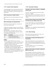
... with Editing Control Unit PVE-500 When setting initial speed to the maintenance manual volume-1 (Section 3). 1-28 HDW-2000/M2000/M2000P/S2000/S2000P/M2100/M2100P, DVW-2000/2000P/M2000/M2000P MSW-2000/A2000/A2000P/M2000/M2000P/M2000E/M2000EP/M2100/M2100P/M2100E/M2100EP For detail of ITEM-F series, refer ...is not necessary. Other Settings When make the following settings, please contact your local Sony Sales Office/Service Center. When Connecting to the PB mode. . Video/Sync Delay Setting "ITEM-701" (DVW/MSW recorder only) Commonly, when integrating the menu into the editing system, set...
... with Editing Control Unit PVE-500 When setting initial speed to the maintenance manual volume-1 (Section 3). 1-28 HDW-2000/M2000/M2000P/S2000/S2000P/M2100/M2100P, DVW-2000/2000P/M2000/M2000P MSW-2000/A2000/A2000P/M2000/M2000P/M2000E/M2000EP/M2100/M2100P/M2100E/M2100EP For detail of ITEM-F series, refer ...is not necessary. Other Settings When make the following settings, please contact your local Sony Sales Office/Service Center. When Connecting to the PB mode. . Video/Sync Delay Setting "ITEM-701" (DVW/MSW recorder only) Commonly, when integrating the menu into the editing system, set...
Product Manual (dvwm2000 installation manual)
Page 35
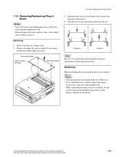
Removing/Reattaching Plug-in board to the connector on the chassis, and then secure the lid. nance manual, volume-1. After inserting the board, push in the two folded eject levers simultaneously to their structural feature. When reattaching the upper lid (rear) assembly, be ... n The AU-272 and EQ-84 boards should be sure to the mainte- Remove the upper lid (rear) assembly by the arrow. HDW-2000/M2000/M2000P/S2000/S2000P/M2100/M2100P, DVW-2000/2000P/M2000/M2000P MSW-2000/A2000/A2000P/M2000/M2000P/M2000E/M2000EP/M2100/M2100P/M2100E/M2100EP 1-29
Removing/Reattaching Plug-in board to the connector on the chassis, and then secure the lid. nance manual, volume-1. After inserting the board, push in the two folded eject levers simultaneously to their structural feature. When reattaching the upper lid (rear) assembly, be ... n The AU-272 and EQ-84 boards should be sure to the mainte- Remove the upper lid (rear) assembly by the arrow. HDW-2000/M2000/M2000P/S2000/S2000P/M2100/M2100P, DVW-2000/2000P/M2000/M2000P MSW-2000/A2000/A2000P/M2000/M2000P/M2000E/M2000EP/M2100/M2100P/M2100E/M2100EP 1-29
Product Manual (dvwm2000 installation manual)
Page 36
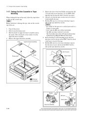
... holder 1-30 Removal Installation M gear EJECT label ME wire EJECT label Wire holder Gear box assembly HDW-2000/M2000/M2000P/S2000/S2000P/M2100/M2100P, DVW-2000/2000P/M2000/M2000P MSW-2000/A2000/A2000P/M2000/M2000P/M2000E/M2000EP/M2100/M2100P/M2100E/M2100EP n Being careful not to catch in the inside the cassette. m . Rotate the M gear... direction) by about 6 mm. 8. 1-17. Release the lock of arrow shown in the EJECT label by pulling the ME wire about a half turn to wind manually the tape. 7.
... holder 1-30 Removal Installation M gear EJECT label ME wire EJECT label Wire holder Gear box assembly HDW-2000/M2000/M2000P/S2000/S2000P/M2100/M2100P, DVW-2000/2000P/M2000/M2000P MSW-2000/A2000/A2000P/M2000/M2000P/M2000E/M2000EP/M2100/M2100P/M2100E/M2100EP n Being careful not to catch in the inside the cassette. m . Rotate the M gear... direction) by about 6 mm. 8. 1-17. Release the lock of arrow shown in the EJECT label by pulling the ME wire about a half turn to wind manually the tape. 7.
Product Manual (dvwm2000 installation manual)
Page 39
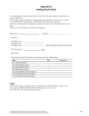
...(Make use of the check sheets in MSW-A2000/A2000P with SY ROM version 1.09 or earlier.) For details, refer to the maintenance manual volume 1. If the unit is used frequently by changing operating condition, the setting can be reset easily. ITEM H01: OPERATION HOURS H02:...SY ROM version SV ROM version VN ROM version MSW-M2000E/M2000EP/M2100E/M2100EP) . HDW-2000/M2000/M2000P/S2000/S2000P/M2100/M2100P, DVW-2000/2000P/M2000/M2000P MSW-2000/A2000/A2000P/M2000/M2000P/M2000E/M2000EP/M2100/M2100P/M2100E/M2100EP A-1 Appendix A Setting Check Sheet It is recommended to copy these ...
...(Make use of the check sheets in MSW-A2000/A2000P with SY ROM version 1.09 or earlier.) For details, refer to the maintenance manual volume 1. If the unit is used frequently by changing operating condition, the setting can be reset easily. ITEM H01: OPERATION HOURS H02:...SY ROM version SV ROM version VN ROM version MSW-M2000E/M2000EP/M2100E/M2100EP) . HDW-2000/M2000/M2000P/S2000/S2000P/M2100/M2100P, DVW-2000/2000P/M2000/M2000P MSW-2000/A2000/A2000P/M2000/M2000P/M2000E/M2000EP/M2100/M2100P/M2100E/M2100EP A-1 Appendix A Setting Check Sheet It is recommended to copy these ...


