
Product Brochure (v2222)
Page 7
..., AES/EBU, 48 kHz fixed, complies with AES-3id-1995 D-sub 9-pin (x2), Sony 9-pin remote interface D-sub 9-pin (x1), RS-232C interface D-sub 50-pin (x1...selectable) T1=50 µs, T2=15 µs PSW 4x16 Rack mount screw (x4), Operation manual (x1), Installation manual (x1) *ISR: Interactive Status Reporting 7 SPECIFICATIONS General Power requirements Power consumption Operating temperature Storage ...Analog input to analog output Head room Emphasis (ON/OFF selectable in REC mode) Supplied accessories DVW-M2000/M2000P DVW-2000/2000P AC 100 V to 240 V, 50/60 Hz 220 W +5 ˚C ...
..., AES/EBU, 48 kHz fixed, complies with AES-3id-1995 D-sub 9-pin (x2), Sony 9-pin remote interface D-sub 9-pin (x1), RS-232C interface D-sub 50-pin (x1...selectable) T1=50 µs, T2=15 µs PSW 4x16 Rack mount screw (x4), Operation manual (x1), Installation manual (x1) *ISR: Interactive Status Reporting 7 SPECIFICATIONS General Power requirements Power consumption Operating temperature Storage ...Analog input to analog output Head room Emphasis (ON/OFF selectable in REC mode) Supplied accessories DVW-M2000/M2000P DVW-2000/2000P AC 100 V to 240 V, 50/60 Hz 220 W +5 ˚C ...
Product Manual (dvwm2000 installation manual)
Page 3
... When this product is provided with a suitable protective earth connection. 3. HDW-2000/M2000/M2000P/S2000/S2000P/M2100/M2100P, DVW-2000/2000P/M2000/M2000P MSW-2000/A2000/A2000P/M2000/M2000P/M2000E/M2000EP/M2100/M2100P/M2100E/M2100EP 1 (P) Internal air ambient temperature of the Operation Manual. 6. Install the equipment while taking the operating temperature of the equipment into consideration...
... When this product is provided with a suitable protective earth connection. 3. HDW-2000/M2000/M2000P/S2000/S2000P/M2100/M2100P, DVW-2000/2000P/M2000/M2000P MSW-2000/A2000/A2000P/M2000/M2000P/M2000E/M2000EP/M2100/M2100P/M2100E/M2100EP 1 (P) Internal air ambient temperature of the Operation Manual. 6. Install the equipment while taking the operating temperature of the equipment into consideration...
Product Manual (dvwm2000 installation manual)
Page 5
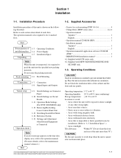
...Connector Panel 1-15 1-10. SS-89 Board 1-20 1-10-5. Operation Mode Settings (For DVW-2000/M2000 Only 1-21 1-11-1. Operation Procedure of this manual 2 Related manuals ...2 1. Switching Search Dial Mode 1-24 1-14. Player 1-25 1-15. Other Settings...and Cables 1-9 1-8. Installation 1-1. Installation Procedure 1-1 1-2. Operating Conditions 1-1 1-4. Installation Space 1-3 1-6. Connection 1-8 1-7-1. Signal Inputs and Outputs 1-10 1-9. AU-272 Board (Other than MSW-2000/A2000/A2000P) ....... 1-19 1-10-4. CUE-13 Board (Other than HDW-2000, DVW-2000/2000P, MSW-...
...Connector Panel 1-15 1-10. SS-89 Board 1-20 1-10-5. Operation Mode Settings (For DVW-2000/M2000 Only 1-21 1-11-1. Operation Procedure of this manual 2 Related manuals ...2 1. Switching Search Dial Mode 1-24 1-14. Player 1-25 1-15. Other Settings...and Cables 1-9 1-8. Installation 1-1. Installation Procedure 1-1 1-2. Operating Conditions 1-1 1-4. Installation Space 1-3 1-6. Connection 1-8 1-7-1. Signal Inputs and Outputs 1-10 1-9. AU-272 Board (Other than MSW-2000/A2000/A2000P) ....... 1-19 1-10-4. CUE-13 Board (Other than HDW-2000, DVW-2000/2000P, MSW-...
Product Manual (dvwm2000 installation manual)
Page 6
.../S2000/S2000P/M2100/M2100P, DVW-2000/2000P/M2000/M2000P MSW-2000/A2000/A2000P/M2000/M2000P/M2000E/M2000EP/M2100/M2100P/M2100E/M2100EP Semiconductors that is the installation manual of the following manuals are listed in this unit. Maintenance Manual (Available on request) This manual explains the protocol for this unit. . Manual Structure Purpose of this manual This manual is required to search...
.../S2000/S2000P/M2100/M2100P, DVW-2000/2000P/M2000/M2000P MSW-2000/A2000/A2000P/M2000/M2000P/M2000E/M2000EP/M2100/M2100P/M2100E/M2100EP Semiconductors that is the installation manual of the following manuals are listed in this unit. Maintenance Manual (Available on request) This manual explains the protocol for this unit. . Manual Structure Purpose of this manual This manual is required to search...
Product Manual (dvwm2000 installation manual)
Page 7
.... . Switch Settings on Connector Panel 1-10. Operation Mode Settings (For DVW-2000/M2000 only) 1-12. Settings and Adjustment when External Equipment is impossible to find a specified room for rack mounting (PSW 4 x 16 4 . Installation Space".) . Do not reuse the packing materials. Connection 1-8. Operation manual Japanese *1 1 English 1 . Installation manual Japanese*1 1 English 1 . Do not block the ventilation holes of...
.... . Switch Settings on Connector Panel 1-10. Operation Mode Settings (For DVW-2000/M2000 only) 1-12. Settings and Adjustment when External Equipment is impossible to find a specified room for rack mounting (PSW 4 x 16 4 . Installation Space".) . Do not reuse the packing materials. Connection 1-8. Operation manual Japanese *1 1 English 1 . Installation manual Japanese*1 1 English 1 . Do not block the ventilation holes of...
Product Manual (dvwm2000 installation manual)
Page 21
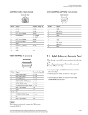
Signal Inputs and Outputs 1-9. Switch Settings on Connector Panel When the unit is installed, be sure to perform the following setup. GND RM TX (+) RM RX (_) GND VIDEO CONTROL: 15-pin (male) External view 1 8 9 15 Pin No. Switch Settings ... 12 13 14 NC Y/C DELAY CONT (Input) NC -- _5 to the operation manual "Section 2 Location and Function of composite video input (DVW/MSW recorder only) HDW-2000/M2000/M2000P/S2000/S2000P/M2100/M2100P, DVW-2000/2000P/M2000/M2000P MSW-2000/A2000/A2000P/M2000/M2000P/M2000E/M2000EP/M2100/M2100P/M2100E/M2100EP 1-15 Refer to +5 -- 15 REG +12V...
Signal Inputs and Outputs 1-9. Switch Settings on Connector Panel When the unit is installed, be sure to perform the following setup. GND RM TX (+) RM RX (_) GND VIDEO CONTROL: 15-pin (male) External view 1 8 9 15 Pin No. Switch Settings ... 12 13 14 NC Y/C DELAY CONT (Input) NC -- _5 to the operation manual "Section 2 Location and Function of composite video input (DVW/MSW recorder only) HDW-2000/M2000/M2000P/S2000/S2000P/M2100/M2100P, DVW-2000/2000P/M2000/M2000P MSW-2000/A2000/A2000P/M2000/M2000P/M2000E/M2000EP/M2100/M2100P/M2100E/M2100EP 1-15 Refer to +5 -- 15 REG +12V...
Product Manual (dvwm2000 installation manual)
Page 27
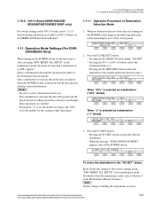
VN-13 Board (MSW-M2000E/ M2000EP/M2100E/M2100EP only) 1-11-1. Operation Mode Settings (For DVW2000/M2000 Only) When turning on VN-13 Board" in the BKMW-E3000 Installation Manual. 1-11. If no destination has not been selected, turning on and the unit operates with the selected destination. NO-SET ... SEL - J RETURN _ + SET F1 F2 F3 F4 F5 F6 3. appears, turn off the POWER switch. 1-10. Operation Mode Settings (For DVW-2000/M2000 Only) 1-10-5. Switch Setting and Function of LEDs on the POWER switch for the first time or after executing "M49: RESET ALL SETUP" in the...
VN-13 Board (MSW-M2000E/ M2000EP/M2100E/M2100EP only) 1-11-1. Operation Mode Settings (For DVW2000/M2000 Only) When turning on VN-13 Board" in the BKMW-E3000 Installation Manual. 1-11. If no destination has not been selected, turning on and the unit operates with the selected destination. NO-SET ... SEL - J RETURN _ + SET F1 F2 F3 F4 F5 F6 3. appears, turn off the POWER switch. 1-10. Operation Mode Settings (For DVW-2000/M2000 Only) 1-10-5. Switch Setting and Function of LEDs on the POWER switch for the first time or after executing "M49: RESET ALL SETUP" in the...
Product Manual (dvwm2000 installation manual)
Page 35
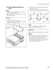
...plug-in board to the mainte- Remove the upper lid (rear) assembly by moving in Board 1-16. Reattaching When reattaching the board, install in the square holes on both ends of the board in Board m . Removing/Reattaching Plug-in the direction indicated by the arrow. ...with stopper Upper lid (rear) assembly Screw with stopper 3. HDW-2000/M2000/M2000P/S2000/S2000P/M2100/M2100P, DVW-2000/2000P/M2000/M2000P MSW-2000/A2000/A2000P/M2000/M2000P/M2000E/M2000EP/M2100/M2100P/M2100E/M2100EP 1-29 nance manual, volume-1. Open the eject levers on the chassis, and then secure the...
...plug-in board to the mainte- Remove the upper lid (rear) assembly by moving in Board 1-16. Reattaching When reattaching the board, install in the square holes on both ends of the board in Board m . Removing/Reattaching Plug-in the direction indicated by the arrow. ...with stopper Upper lid (rear) assembly Screw with stopper 3. HDW-2000/M2000/M2000P/S2000/S2000P/M2100/M2100P, DVW-2000/2000P/M2000/M2000P MSW-2000/A2000/A2000P/M2000/M2000P/M2000E/M2000EP/M2100/M2100P/M2100E/M2100EP 1-29 nance manual, volume-1. Open the eject levers on the chassis, and then secure the...
Product Manual (dvwm2000 installation manual)
Page 36
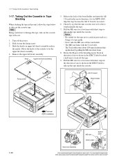
... screw Knob AE-31 board Board holder 1-30 Removal Installation M gear EJECT label ME wire EJECT label Wire holder Gear box assembly HDW-2000/M2000/M2000P/S2000/S2000P/M2100/M2100P, DVW-2000/2000P/M2000/M2000P MSW-2000/A2000/A2000P/M2000/M2000P/M2000E/M2000EP/M2100/M2100P/M2100E/M2100EP Slide the knobs... on upper lid (front) assembly each in the state to be able to damage the tape, take up the tape inside the cassette. 1-17. n Being careful not to wind manually...
... screw Knob AE-31 board Board holder 1-30 Removal Installation M gear EJECT label ME wire EJECT label Wire holder Gear box assembly HDW-2000/M2000/M2000P/S2000/S2000P/M2100/M2100P, DVW-2000/2000P/M2000/M2000P MSW-2000/A2000/A2000P/M2000/M2000P/M2000E/M2000EP/M2100/M2100P/M2100E/M2100EP Slide the knobs... on upper lid (front) assembly each in the state to be able to damage the tape, take up the tape inside the cassette. 1-17. n Being careful not to wind manually...


