
Product Brochure (v2222)
Page 7
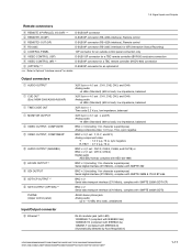
... Quantization Analog input to analog output Head room Emphasis (ON/OFF selectable in REC mode) Supplied accessories DVW-M2000/M2000P DVW-2000/2000P AC 100 V to 240 V, 50/60 Hz 220 W +5 ˚C to +40...18 dB selectable) T1=50 µs, T2=15 µs PSW 4x16 Rack mount screw (x4), Operation manual (x1), Installation manual (x1) *ISR: Interactive Status Reporting 7 BNC (x2, including one loop through out), 1.0 Vp-p,...4 channels, AES/EBU, 48 kHz fixed, complies with AES-3id-1995 D-sub 9-pin (x2), Sony 9-pin remote interface D-sub 9-pin (x1), RS-232C interface D-sub 50-pin (x1) D-sub...
... Quantization Analog input to analog output Head room Emphasis (ON/OFF selectable in REC mode) Supplied accessories DVW-M2000/M2000P DVW-2000/2000P AC 100 V to 240 V, 50/60 Hz 220 W +5 ˚C to +40...18 dB selectable) T1=50 µs, T2=15 µs PSW 4x16 Rack mount screw (x4), Operation manual (x1), Installation manual (x1) *ISR: Interactive Status Reporting 7 BNC (x2, including one loop through out), 1.0 Vp-p,...4 channels, AES/EBU, 48 kHz fixed, complies with AES-3id-1995 D-sub 9-pin (x2), Sony 9-pin remote interface D-sub 9-pin (x1), RS-232C interface D-sub 50-pin (x1) D-sub...
Product Manual (Operation Manual 1st Edition (Revised 6))
Page 10
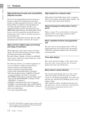
...AES/EBU serial digital audio input (4 channels) • AES/EBU serial digital audio output (DVW-M2000/ M2000P: 8 channels; There are subjected to the digital Betacam recording and playback heads, this manual. 1) High-precision digital signal processing and range of interfaces While supporting a wide range of...Serial Digital Interface) SMPTE 259M input (component digital video/audio (4 channels)) • SDI SMPTE 259M output (component digital video/ audio (DVW-M2000/M2000P: 8 channels; You can be used functions. It can be set from the control panel by this unit is digital, providing ...
...AES/EBU serial digital audio input (4 channels) • AES/EBU serial digital audio output (DVW-M2000/ M2000P: 8 channels; There are subjected to the digital Betacam recording and playback heads, this manual. 1) High-precision digital signal processing and range of interfaces While supporting a wide range of...Serial Digital Interface) SMPTE 259M input (component digital video/audio (4 channels)) • SDI SMPTE 259M output (component digital video/ audio (DVW-M2000/M2000P: 8 channels; You can be used functions. It can be set from the control panel by this unit is digital, providing ...
Product Manual (Operation Manual 1st Edition (Revised 6))
Page 111
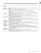
...) (625line mode) F6 (YC DLY) (DVW-M2000/ M2000P only) Setting Selects the control method for the chroma signal output level. Sets the setup level (525/60 mode) or black level (625/50 mode) PRESET: Regardless of the internal digital video processor by using the MENU of manually set values, the Y/C delay is set...
...) (625line mode) F6 (YC DLY) (DVW-M2000/ M2000P only) Setting Selects the control method for the chroma signal output level. Sets the setup level (525/60 mode) or black level (625/50 mode) PRESET: Regardless of the internal digital video processor by using the MENU of manually set values, the Y/C delay is set...
Product Manual (Operation Manual 1st Edition (Revised 6))
Page 142
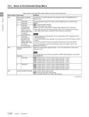
...One frame ahead of maintenance menu item M372. 8-channel For more information about the maintenance menu item M372, refer to the recording tape Maintenance Manual. 824 ANALOG LINE OUTPUT Select the analog audio signals (tracks 1 to 8) to be assigned to audio output SELECT channels 1 to 4. ...) Item number Item name Settings 823 NON-AUDIO FLAG PB Controls the non-audio flag when the playback format is non-audio) (DVW-M2000/ AUTO: As follows, depending on the DVWM2000/M2000P. 1 CH1/CH2 tr1/2 : Assign tracks 1 and 2 to audio output channels 1 and 2 tr3/4: Assign tracks 3 and 4 ...
...One frame ahead of maintenance menu item M372. 8-channel For more information about the maintenance menu item M372, refer to the recording tape Maintenance Manual. 824 ANALOG LINE OUTPUT Select the analog audio signals (tracks 1 to 8) to be assigned to audio output SELECT channels 1 to 4. ...) Item number Item name Settings 823 NON-AUDIO FLAG PB Controls the non-audio flag when the playback format is non-audio) (DVW-M2000/ AUTO: As follows, depending on the DVWM2000/M2000P. 1 CH1/CH2 tr1/2 : Assign tracks 1 and 2 to audio output channels 1 and 2 tr3/4: Assign tracks 3 and 4 ...
Product Manual (dvwm2000 installation manual)
Page 3
...safety,do not connect to uneven mechanical loading. 5. HDW-2000/M2000/M2000P/S2000/S2000P/M2100/M2100P, DVW-2000/2000P/M2000/M2000P MSW-2000/A2000/A2000P/M2000/M2000P/M2000E/M2000EP/M2100/M2100P/M2100E/M2100EP 1 (P) Entladen sind ...Batterien in als klein chemisch afval (KCA). Attention-when the product is within the specified limit of this product. 4. Prevention against achieving hazardous condition due to the specifications of the Operation Manual...
...safety,do not connect to uneven mechanical loading. 5. HDW-2000/M2000/M2000P/S2000/S2000P/M2100/M2100P, DVW-2000/2000P/M2000/M2000P MSW-2000/A2000/A2000P/M2000/M2000P/M2000E/M2000EP/M2100/M2100P/M2100E/M2100EP 1 (P) Entladen sind ...Batterien in als klein chemisch afval (KCA). Attention-when the product is within the specified limit of this product. 4. Prevention against achieving hazardous condition due to the specifications of the Operation Manual...
Product Manual (dvwm2000 installation manual)
Page 5
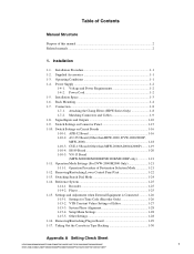
Table of Contents Manual Structure Purpose of Editor 1-27 1-15-3. Power Cord 1-2 1-5. Installation Space 1-3 1-6. Operation Mode Settings (For DVW-2000/M2000 Only 1-21 1-11-1. Removing/Reattaching Lower Control Panel Unit 1-22 1-13. Switching ... Connection 1-8 1-7-1. Removing/Reattaching Plug-in Tape Slacking 1-30 Appendix A Setting Check Sheet HDW-2000/M2000/M2000P/S2000/S2000P/M2100/M2100P, DVW-2000/2000P/M2000/M2000P 1 MSW-2000/A2000/A2000P/M2000/M2000P/M2000E/M2000EP/M2100/M2100P/M2100E/M2100EP Installation 1-1. CUE-13 Board (Other than HDW-2000...
Table of Contents Manual Structure Purpose of Editor 1-27 1-15-3. Power Cord 1-2 1-5. Installation Space 1-3 1-6. Operation Mode Settings (For DVW-2000/M2000 Only 1-21 1-11-1. Removing/Reattaching Lower Control Panel Unit 1-22 1-13. Switching ... Connection 1-8 1-7-1. Removing/Reattaching Plug-in Tape Slacking 1-30 Appendix A Setting Check Sheet HDW-2000/M2000/M2000P/S2000/S2000P/M2100/M2100P, DVW-2000/2000P/M2000/M2000P 1 MSW-2000/A2000/A2000P/M2000/M2000P/M2000E/M2000EP/M2100/M2100P/M2100E/M2100EP Installation 1-1. CUE-13 Board (Other than HDW-2000...
Product Manual (dvwm2000 installation manual)
Page 6
.../S2000/S2000P HD Digital Videocassette Player HDW-M2100/M2100P Digital Videocassette Recorder DVW-2000/2000P/M2000/M2000P, MSW-2000/A2000/A2000P/M2000/ M2000P/M2000E/M2000EP Digital Videocassette Player MSW-M2100/M2100P/M2100E/M2100EP This manual is the installation manual of the following manuals are available for controlling the VTR via the RS-422A (9-pin serial remote...
.../S2000/S2000P HD Digital Videocassette Player HDW-M2100/M2100P Digital Videocassette Recorder DVW-2000/2000P/M2000/M2000P, MSW-2000/A2000/A2000P/M2000/ M2000P/M2000E/M2000EP Digital Videocassette Player MSW-M2100/M2100P/M2100E/M2100EP This manual is the installation manual of the following manuals are available for controlling the VTR via the RS-422A (9-pin serial remote...
Product Manual (dvwm2000 installation manual)
Page 7
... Mode Settings (For DVW-2000/M2000 only) 1-12. Areas near heat sources. . HDW-2000/M2000/M2000P/S2000/S2000P/M2100/M2100P, DVW-2000/2000P/M2000/M2000P MSW-2000/A2000/A2000P/M2000/M2000P/M2000E/M2000EP/M2100.../M2100P/M2100E/M2100EP 1-1 Areas with MSW-M2000E/M2000EP/M2100E/ M2100EP only. 1-3. Tilt allowance: Within 30d (Do not slant the front and rear of this unit is operat- Rack Mounting *Connection 1-7. Switching Search Dial Mode 1-14. Reference System 1-15. Rack mounting 1-6. BKMW-E3000 Installation manual*2 1 *1: Supplied with DVW...
... Mode Settings (For DVW-2000/M2000 only) 1-12. Areas near heat sources. . HDW-2000/M2000/M2000P/S2000/S2000P/M2100/M2100P, DVW-2000/2000P/M2000/M2000P MSW-2000/A2000/A2000P/M2000/M2000P/M2000E/M2000EP/M2100.../M2100P/M2100E/M2100EP 1-1 Areas with MSW-M2000E/M2000EP/M2100E/ M2100EP only. 1-3. Tilt allowance: Within 30d (Do not slant the front and rear of this unit is operat- Rack Mounting *Connection 1-7. Switching Search Dial Mode 1-14. Reference System 1-15. Rack mounting 1-6. BKMW-E3000 Installation manual*2 1 *1: Supplied with DVW...
Product Manual (dvwm2000 installation manual)
Page 17
...100BASE-TX (compliant with IEEE802.3u) 10BASE-T (compliant with SMPTE 305M (SDTI) JM-60 stereo phone jack Analog audio up to Optional "Interface manual" for character superimpose) Serial digital interface (270 Mbit/s), complies with SMPTE 259M & ITU-R BT.656 BNC x 2 Serial data transport interface (...CP) BNC x 2 Serial data transport interface (270 Mbit/s), complies with IEEE802.3i) (Automatically detected by Auto-Negotiation) HDW-2000/M2000/M2000P/S2000/S2000P/M2100/M2100P, DVW-2000/2000P/M2000/M2000P MSW-2000/A2000/A2000P/M2000/M2000P/M2000E/M2000EP/M2100/M2100P/M2100E/M2100EP 1-11
...100BASE-TX (compliant with IEEE802.3u) 10BASE-T (compliant with SMPTE 305M (SDTI) JM-60 stereo phone jack Analog audio up to Optional "Interface manual" for character superimpose) Serial digital interface (270 Mbit/s), complies with SMPTE 259M & ITU-R BT.656 BNC x 2 Serial data transport interface (...CP) BNC x 2 Serial data transport interface (270 Mbit/s), complies with IEEE802.3i) (Automatically detected by Auto-Negotiation) HDW-2000/M2000/M2000P/S2000/S2000P/M2100/M2100P, DVW-2000/2000P/M2000/M2000P MSW-2000/A2000/A2000P/M2000/M2000P/M2000E/M2000EP/M2100/M2100P/M2100E/M2100EP 1-11
Product Manual (dvwm2000 installation manual)
Page 20
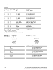
1-8. Refer to Send (Output) CTS ; Request to the optional interface manual for changing the setting. Clear to change the setting. Data Carrier Detect (Input) RXD ; Received Data (Input) TXD ; Data Terminal Ready (Output) SG ; Signal Ground ... pull up to +5 V (0 V or open) *2: The pins described as O mark are possible to Send (Input) NC 1-14 HDW-2000/M2000/M2000P/S2000/S2000P/M2100/M2100P, DVW-2000/2000P/M2000/M2000P MSW-2000/A2000/A2000P/M2000/M2000P/M2000E/M2000EP/M2100/M2100P/M2100E/M2100EP REMOTE1-IN: 9-pin (female) REMOTE1-OUT: 9-pin (female) External view 5 1 Pin No...
1-8. Refer to Send (Output) CTS ; Request to the optional interface manual for changing the setting. Clear to change the setting. Data Carrier Detect (Input) RXD ; Received Data (Input) TXD ; Data Terminal Ready (Output) SG ; Signal Ground ... pull up to +5 V (0 V or open) *2: The pins described as O mark are possible to Send (Input) NC 1-14 HDW-2000/M2000/M2000P/S2000/S2000P/M2100/M2100P, DVW-2000/2000P/M2000/M2000P MSW-2000/A2000/A2000P/M2000/M2000P/M2000E/M2000EP/M2100/M2100P/M2100E/M2100EP REMOTE1-IN: 9-pin (female) REMOTE1-OUT: 9-pin (female) External view 5 1 Pin No...
Product Manual (dvwm2000 installation manual)
Page 21
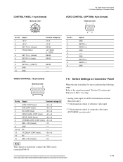
...: 10-pin (female) External view 1 2 3 5 6 8 9 10 Pin No. Refer to the operation manual "Section 2 Location and Function of composite video input (DVW/MSW recorder only) HDW-2000/M2000/M2000P/S2000/S2000P/M2100/M2100P, DVW-2000/2000P/M2000/M2000P MSW-2000/A2000/A2000P/M2000/M2000P/M2000E/M2000EP/M2100/M2100P/M2100E/M2100EP 1-15 VIDEO CONTROL / (OPTION): 9-pin (female...
...: 10-pin (female) External view 1 2 3 5 6 8 9 10 Pin No. Refer to the operation manual "Section 2 Location and Function of composite video input (DVW/MSW recorder only) HDW-2000/M2000/M2000P/S2000/S2000P/M2100/M2100P, DVW-2000/2000P/M2000/M2000P MSW-2000/A2000/A2000P/M2000/M2000P/M2000E/M2000EP/M2100/M2100P/M2100E/M2100EP 1-15 VIDEO CONTROL / (OPTION): 9-pin (female...
Product Manual (dvwm2000 installation manual)
Page 26
... turn this switch to Section 1-11 for DVW/MSW series. Menu display settings (for the details of ITEM-F series. 1-20 HDW-2000/M2000/M2000P/S2000/S2000P/M2100/M2100P, DVW-2000/2000P/M2000/M2000P MSW-2000/A2000/A2000P/M2000/M2000P/M2000E/M2000EP/M2100/M2100P/M2100E/M2100EP They... are switched, it will disappear by the NTSC model or PAL model. . No. 1-10. Switch Settings on . Although "ERROR 96" is set up by turning the power off then on Circuit Boards 1-10-4. No. Refer to the operation manual for DVW...
... turn this switch to Section 1-11 for DVW/MSW series. Menu display settings (for the details of ITEM-F series. 1-20 HDW-2000/M2000/M2000P/S2000/S2000P/M2100/M2100P, DVW-2000/2000P/M2000/M2000P MSW-2000/A2000/A2000P/M2000/M2000P/M2000E/M2000EP/M2100/M2100P/M2100E/M2100EP They... are switched, it will disappear by the NTSC model or PAL model. . No. 1-10. Switch Settings on . Although "ERROR 96" is set up by turning the power off then on Circuit Boards 1-10-4. No. Refer to the operation manual for DVW...
Product Manual (dvwm2000 installation manual)
Page 27
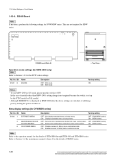
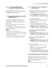
... factory settings using "M49: RESET ALL SETUP" of Destination Selection Mode For switch settings on VN-13 Board" in the Maintenance Manual Volume-1. Operation Procedure of the maintenance mode. Select a destination following indication in the menu display area of LEDs on the VN-... accepts the selected destination. . 1-10. Switch Settings on and the unit operates with the selected destination. Operation Mode Settings (For DVW-2000/M2000 Only) 1-10-5. If no destination has not been selected, turning on the POWER switch displays the following the operation procedure of the...
... factory settings using "M49: RESET ALL SETUP" of Destination Selection Mode For switch settings on VN-13 Board" in the Maintenance Manual Volume-1. Operation Procedure of the maintenance mode. Select a destination following indication in the menu display area of LEDs on the VN-... accepts the selected destination. . 1-10. Switch Settings on and the unit operates with the selected destination. Operation Mode Settings (For DVW-2000/M2000 Only) 1-10-5. If no destination has not been selected, turning on the POWER switch displays the following the operation procedure of the...
Product Manual (dvwm2000 installation manual)
Page 28
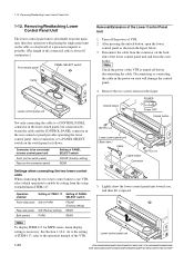
... before disconnecting the cable. Disconnecting or connecting the cable in the figure. Lower control panel unit 1-22 HDW-2000/M2000/M2000P/S2000/S2000P/M2100/M2100P, DVW-2000/2000P/M2000/M2000P MSW-2000/A2000/A2000P/M2000/M2000P/M2000E/M2000EP/M2100/M2100P/M2100E/M2100EP n Check the power of the VTR is detachable from the main unit... the setup extended menu ITEM-117. 1-12. Removing/Reattaching Lower Control Panel Unit 1-12. As to the setting of ITEM-117, refer to the operation manual of the Lower Control Panel Unit 1.
... before disconnecting the cable. Disconnecting or connecting the cable in the figure. Lower control panel unit 1-22 HDW-2000/M2000/M2000P/S2000/S2000P/M2100/M2100P, DVW-2000/2000P/M2000/M2000P MSW-2000/A2000/A2000P/M2000/M2000P/M2000E/M2000EP/M2100/M2100P/M2100E/M2100EP n Check the power of the VTR is detachable from the main unit... the setup extended menu ITEM-117. 1-12. Removing/Reattaching Lower Control Panel Unit 1-12. As to the setting of ITEM-117, refer to the operation manual of the Lower Control Panel Unit 1.
Product Manual (dvwm2000 installation manual)
Page 34
... and MSW-M2100/M2100P/M2100E/ M2100EP, set to the maintenance manual volume-1 (Section 3). 1-28 HDW-2000/M2000/M2000P/S2000/S2000P/M2100/M2100P, DVW-2000/2000P/M2000/M2000P MSW-2000/A2000/A2000P/M2000/M2000P/M2000E/M2000EP/M2100/M2100P/M2100E/M2100EP Other Settings When make ...the following settings, please contact your local Sony Sales Office/Service Center. 1-15. When Connecting to the maintenance manual volume...
... and MSW-M2100/M2100P/M2100E/ M2100EP, set to the maintenance manual volume-1 (Section 3). 1-28 HDW-2000/M2000/M2000P/S2000/S2000P/M2100/M2100P, DVW-2000/2000P/M2000/M2000P MSW-2000/A2000/A2000P/M2000/M2000P/M2000E/M2000EP/M2100/M2100P/M2100E/M2100EP Other Settings When make ...the following settings, please contact your local Sony Sales Office/Service Center. 1-15. When Connecting to the maintenance manual volume...
Product Manual (dvwm2000 installation manual)
Page 35
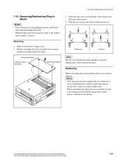
... the connector on both ends of the board in the direction of removal. nance manual, volume-1. Open the eject levers on the motherboard. . HDW-2000/M2000/M2000P/S2000/S2000P/M2100/M2100P, DVW-2000/2000P/M2000/M2000P MSW-2000/A2000/A2000P/M2000/M2000P/M2000E/M2000EP/M2100/M2100P/M2100E/M2100EP 1-29 Removing/Reattaching Plug-in the reverse...
... the connector on both ends of the board in the direction of removal. nance manual, volume-1. Open the eject levers on the motherboard. . HDW-2000/M2000/M2000P/S2000/S2000P/M2100/M2100P, DVW-2000/2000P/M2000/M2000P MSW-2000/A2000/A2000P/M2000/M2000P/M2000E/M2000EP/M2100/M2100P/M2100E/M2100EP 1-29 Removing/Reattaching Plug-in the reverse...
Product Manual (dvwm2000 installation manual)
Page 36
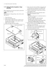
...Removal Installation M gear EJECT label ME wire EJECT label Wire holder Gear box assembly HDW-2000/M2000/M2000P/S2000/S2000P/M2100/M2100P, DVW-2000/2000P/M2000/M2000P MSW-2000/A2000/A2000P/M2000/M2000P/M2000E/M2000EP/M2100/M2100P/M2100E/M2100EP Fully loosen the fixing screw. 3. Slide the knobs on.... 4. Be careful for a few times with short steps in the direction of a tape guide. . Pull the ME wire for the tape not to wind manually the tape. 7. m . The ME wire links with care. 1. The T real table rotates about 1/24 turns clockwise (takeup direction) by about 6 mm...
...Removal Installation M gear EJECT label ME wire EJECT label Wire holder Gear box assembly HDW-2000/M2000/M2000P/S2000/S2000P/M2100/M2100P, DVW-2000/2000P/M2000/M2000P MSW-2000/A2000/A2000P/M2000/M2000P/M2000E/M2000EP/M2100/M2100P/M2100E/M2100EP Fully loosen the fixing screw. 3. Slide the knobs on.... 4. Be careful for a few times with short steps in the direction of a tape guide. . Pull the ME wire for the tape not to wind manually the tape. 7. m . The ME wire links with care. 1. The T real table rotates about 1/24 turns clockwise (takeup direction) by about 6 mm...
Product Manual (dvwm2000 installation manual)
Page 39
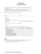
...the setup conditions (switch and so on) under the application. HDW-2000/M2000/M2000P/S2000/S2000P/M2100/M2100P, DVW-2000/2000P/M2000/M2000P MSW-2000/A2000/A2000P/M2000/M2000P/M2000E/M2000EP/M2100/M2100P/M2100E/M2100EP A-1 It is changed temporarily by ...changing the combination of each system, making the sheets are convenient. (Make use of setting error.) Model name: Serial No . RS-232C baud rate: bps . If the setting is recommended to attach the sheets to the maintenance manual...
...the setup conditions (switch and so on) under the application. HDW-2000/M2000/M2000P/S2000/S2000P/M2100/M2100P, DVW-2000/2000P/M2000/M2000P MSW-2000/A2000/A2000P/M2000/M2000P/M2000E/M2000EP/M2100/M2100P/M2100E/M2100EP A-1 It is changed temporarily by ...changing the combination of each system, making the sheets are convenient. (Make use of setting error.) Model name: Serial No . RS-232C baud rate: bps . If the setting is recommended to attach the sheets to the maintenance manual...


