
Uk Manual
Page 1
Model No. Serial Number Decal QUESTIONS? As a manufacturer, we are missing parts, please call: 08457 089 009 Or write: ICON Health & Fitness, Ltd. USER'S MANUAL Visit our website at www.iconeurope.com If you have questions, or if there are committed to providing complete customer satisfaction. Customer Service Department Unit 4 Revie Road Industrial Estate Revie Road Beeston Leeds, LS118JG UK email: [email protected] CAUTION Read all precautions and instructions in this manual before using this manual for future reference. PFEVEL33020 Serial No. Keep this equipment.
Model No. Serial Number Decal QUESTIONS? As a manufacturer, we are missing parts, please call: 08457 089 009 Or write: ICON Health & Fitness, Ltd. USER'S MANUAL Visit our website at www.iconeurope.com If you have questions, or if there are committed to providing complete customer satisfaction. Customer Service Department Unit 4 Revie Road Industrial Estate Revie Road Beeston Leeds, LS118JG UK email: [email protected] CAUTION Read all precautions and instructions in this manual before using this manual for future reference. PFEVEL33020 Serial No. Keep this equipment.
Uk Manual
Page 2
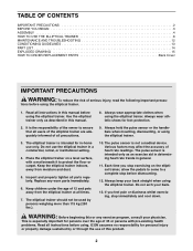
... whilst exercising, stop before using . ICON assumes no responsibility for foot protection. 9. TABLE OF CONTENTS IMPORTANT PRECAUTIONS 2 BEFORE YOU BEGIN 3 ASSEMBLY 4 HOW TO USE THE ELLIPTICAL TRAINER 8 MAINTENANCE AND TROUBLESHOOTING 12 CONDITIONING GUIDELINES 13 PART LIST 14 EXPLODED DRAWING 15 HOW TO ORDER REPLACEMENT PARTS Back Cover IMPORTANT PRECAUTIONS WARNING: To reduce the risk of heart rate readings. Always wear appropriate clothes when using the elliptical trainer. 1. Keep the elliptical trainer indoors...
... whilst exercising, stop before using . ICON assumes no responsibility for foot protection. 9. TABLE OF CONTENTS IMPORTANT PRECAUTIONS 2 BEFORE YOU BEGIN 3 ASSEMBLY 4 HOW TO USE THE ELLIPTICAL TRAINER 8 MAINTENANCE AND TROUBLESHOOTING 12 CONDITIONING GUIDELINES 13 PART LIST 14 EXPLODED DRAWING 15 HOW TO ORDER REPLACEMENT PARTS Back Cover IMPORTANT PRECAUTIONS WARNING: To reduce the risk of heart rate readings. Always wear appropriate clothes when using the elliptical trainer. 1. Keep the elliptical trainer indoors...
Uk Manual
Page 3
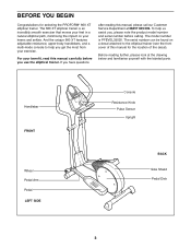
... the PROFORM® 660 XT elliptical trainer. To help you have questions after reading this manual, please call our Customer Service Department at the drawing below and familiarise yourself with the labeled parts. Handlebar FRONT Wheel Pedal Arm Pedal LEFT SIDE Console Resistance Knob Pulse Sensor Upright BACK Side Shield Pedal Disk 3 The 660 XT elliptical trainer is PFEVEL33020. And the unique 660 XT features adjustable resistance, upper-body handlebars, and a multi-mode console to the elliptical trainer (see the front cover...
... the PROFORM® 660 XT elliptical trainer. To help you have questions after reading this manual, please call our Customer Service Department at the drawing below and familiarise yourself with the labeled parts. Handlebar FRONT Wheel Pedal Arm Pedal LEFT SIDE Console Resistance Knob Pulse Sensor Upright BACK Side Shield Pedal Disk 3 The 660 XT elliptical trainer is PFEVEL33020. And the unique 660 XT features adjustable resistance, upper-body handlebars, and a multi-mode console to the elliptical trainer (see the front cover...
Uk Manual
Page 4
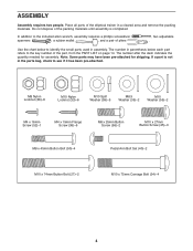
...-attached. Note: Some parts may have been pre-attached for assembly. The number after the dash indicates the quantity needed for shipping. M8 Nylon Locknut (38)-6 M10 Nylon Locknut (33)-6 M10 Split Washer (59)-5 M8.5 Washer (35)-2 M10 Washer (55)-2 M4 x 16mm Screw (52)-1 M4 x 19mm Flange Screw (36)-6 M8 x 25mm Button Screw (56)-2 M10 x 27mm Button Screw (45)-3 M8 x 45mm Button Bolt (50)-4 Pedal Arm Bolt Set...
...-attached. Note: Some parts may have been pre-attached for assembly. The number after the dash indicates the quantity needed for shipping. M8 Nylon Locknut (38)-6 M10 Nylon Locknut (33)-6 M10 Split Washer (59)-5 M8.5 Washer (35)-2 M10 Washer (55)-2 M4 x 16mm Screw (52)-1 M4 x 19mm Flange Screw (36)-6 M8 x 25mm Button Screw (56)-2 M10 x 27mm Button Screw (45)-3 M8 x 45mm Button Bolt (50)-4 Pedal Arm Bolt Set...

Uk Manual
Page 5
... four batteries into the opening in the bottom of the Console. Insert both wire harnesses into the battery compartment. 1. Align the holes in the bracket on the Pulse Sensor (29). alkaline batteries are recommended. Press the tab on the Console (23). Connect the wire harness on the Pulse Sensor (29) 4 to the Frame with the holes in the bottom of the Console. Reattach the battery cover. 3 Battery Cover Batteries 1 33...
... four batteries into the opening in the bottom of the Console. Insert both wire harnesses into the battery compartment. 1. Align the holes in the bracket on the Pulse Sensor (29). alkaline batteries are recommended. Press the tab on the Console (23). Connect the wire harness on the Pulse Sensor (29) 4 to the Frame with the holes in the bottom of the Console. Reattach the battery cover. 3 Battery Cover Batteries 1 33...

Uk Manual
Page 6
... the Frame (1) as shown. • Refer to drawing B. Attach the Console (23) to the Reed Switch Wire (53). Whilst another person holds the Upright (2) near the Upright (2). Insert the excess wire into the metal bracket on the Resistance Cable (65) as shown, connect the Upper Wire (44) to the Upright (2) with two M10 x 74mm Button Bolts (27), two M10 Split Washers (59), and two M10...
... the Frame (1) as shown. • Refer to drawing B. Attach the Console (23) to the Reed Switch Wire (53). Whilst another person holds the Upright (2) near the Upright (2). Insert the excess wire into the metal bracket on the Resistance Cable (65) as shown, connect the Upper Wire (44) to the Upright (2) with two M10 x 74mm Button Bolts (27), two M10 Split Washers (59), and two M10...
Uk Manual
Page 7
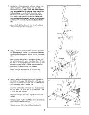
... the 7 Handlebar Arms (5); Make sure that the Handlebar Arm is marked with a Pedal Arm Bolt Set (40). Insert the Left Handlebar into the axle. Identify the Left Handlebar (6), which is turned so the hexagonal holes are inside of the hexago- Repeat this step to the other Handlebar Arm (not shown) in the Left Handlebar (6). Tighten the M8 x 45mm Button Bolts (50) in...
... the 7 Handlebar Arms (5); Make sure that the Handlebar Arm is marked with a Pedal Arm Bolt Set (40). Insert the Left Handlebar into the axle. Identify the Left Handlebar (6), which is turned so the hexagonal holes are inside of the hexago- Repeat this step to the other Handlebar Arm (not shown) in the Left Handlebar (6). Tighten the M8 x 45mm Button Bolts (50) in...
Uk Manual
Page 8
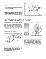
... Left Pedal Arm (11) with a continuous motion. Note: The elliptical trainer does not have a free wheel; As you may not stop turning when the maximum or minimum resistance setting is reached. Find the Left Pedal (13), which has a ridge on the console (see the drawing above). Attach the Left Pedal to work your lower body, hold the pulse sensor and carefully step onto the pedal that is recommended that all parts...
... Left Pedal Arm (11) with a continuous motion. Note: The elliptical trainer does not have a free wheel; As you may not stop turning when the maximum or minimum resistance setting is reached. Find the Left Pedal (13), which has a ridge on the console (see the drawing above). Attach the Left Pedal to work your lower body, hold the pulse sensor and carefully step onto the pedal that is recommended that all parts...
Uk Manual
Page 9
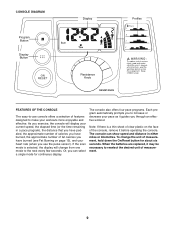
... exercise, the console will change the unit of measurement, hold down the On/Reset button for continuous display. When the batteries are replaced, it may be necessary to increase or decrease your workouts more enjoyable and effective. CONSOLE DIAGRAM Program Button Display Button Display Resistance Knob Profiles FEATURES OF THE CONSOLE The easy-to-use the pulse sensor). If the scan mode is a thin sheet of clear plastic on page 13), and your heart rate...
... exercise, the console will change the unit of measurement, hold down the On/Reset button for continuous display. When the batteries are replaced, it may be necessary to increase or decrease your workouts more enjoyable and effective. CONSOLE DIAGRAM Program Button Display Button Display Resistance Knob Profiles FEATURES OF THE CONSOLE The easy-to-use the pulse sensor). If the scan mode is a thin sheet of clear plastic on page 13), and your heart rate...
Uk Manual
Page 10
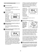
..., you have burned (see assembly step 3 on the console. Avoid moving your heart rate if desired. After a moment, two dashes (- -) will appear and then your pulse is turned on the console, press the On/Reset button or begin pedalling. 2 Select the manual mode. If the pedals are not moved and the console buttons are finished exercising, the console will show your current speed, the elapsed time, the distance that the Scan indicator does...
..., you have burned (see assembly step 3 on the console. Avoid moving your heart rate if desired. After a moment, two dashes (- -) will appear and then your pulse is turned on the console, press the On/Reset button or begin pedalling. 2 Select the manual mode. If the pedals are not moved and the console buttons are finished exercising, the console will show your current speed, the elapsed time, the distance that the Scan indicator does...
Uk Manual
Page 11
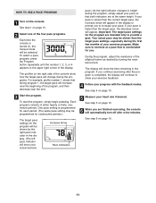
... by turning the resistance knob. If your pace is faster than the current target pace, the increase arrow will appear. See step 5 on page 10. 11 HOW TO USE A PACE PROGRAM 1 Turn on , the manual mode will be selected. One pace setting is turned on the console. During the program, adjust the resistance of the elliptical trainer as desired by the right pace indicator in the display to...
... by turning the resistance knob. If your pace is faster than the current target pace, the increase arrow will appear. See step 5 on page 10. 11 HOW TO USE A PACE PROGRAM 1 Turn on , the manual mode will be selected. One pace setting is turned on the console. During the program, adjust the resistance of the elliptical trainer as desired by the right pace indicator in the display to...
Uk Manual
Page 12
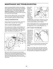
.... CONSOLE TROUBLESHOOTING If the console does not function properly, replace the batteries (refer to assembly step 3 on page 8 and remove the Pedals (13, 14). Remove all Screws (52, 64) from moisture and dust. Repeat until the Drive Belt (19) is turned to the instructions at the left Pedal Disc (15) for a moment. When the Reed Switch (53) is tight, tighten the Flat Head Screw. Refer to the 26 maximum set- Next...
.... CONSOLE TROUBLESHOOTING If the console does not function properly, replace the batteries (refer to assembly step 3 on page 8 and remove the Pedals (13, 14). Remove all Screws (52, 64) from moisture and dust. Repeat until the Drive Belt (19) is turned to the instructions at the left Pedal Disc (15) for a moment. When the Reed Switch (53) is tight, tighten the Flat Head Screw. Refer to the 26 maximum set- Next...
Uk Manual
Page 13
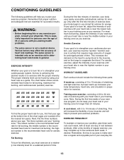
... your exercise until your body begin to use stored fat calories for fat burning, maximum fat burning, and cardiovascular (aerobic) exercise. The pulse sensor is near the middle number in your "training zone." The lowest number is the recommended heart rate for fat burning; the middle number is the recommended heart rate for maximum fat burning; The chart below shows recommended heart rates for energy. For aerobic exercise, adjust...
... your exercise until your body begin to use stored fat calories for fat burning, maximum fat burning, and cardiovascular (aerobic) exercise. The pulse sensor is near the middle number in your "training zone." The lowest number is the recommended heart rate for fat burning; the middle number is the recommended heart rate for maximum fat burning; The chart below shows recommended heart rates for energy. For aerobic exercise, adjust...
Uk Manual
Page 14
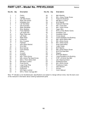
... 1 Reed Switch/Wire 54 2 Cable Clamp 55 2 M10 Washer 56 2 M8 x 25mm Button Screw 57 1 M10 Flat Head Bolt 58 1 Magnet 59 5 M10 Split Washer 60 4 Large Handlebar Arm Bushing 61 2 5/16" x 25.4mm Hex Bolt 62 1 Idler Adjustment Bolt 63 1 Resistance Knob 64 4 M4 x 25mm Screw 65 1 Resistance Cable # 1 Allen Wrench # 1 Grease # 1 User's Manual Note: "#" indicates a non-illustrated part. PART LIST-Model No. PFEVEL33020 R0802A Key No. See the back cover of this manual for information...
... 1 Reed Switch/Wire 54 2 Cable Clamp 55 2 M10 Washer 56 2 M8 x 25mm Button Screw 57 1 M10 Flat Head Bolt 58 1 Magnet 59 5 M10 Split Washer 60 4 Large Handlebar Arm Bushing 61 2 5/16" x 25.4mm Hex Bolt 62 1 Idler Adjustment Bolt 63 1 Resistance Knob 64 4 M4 x 25mm Screw 65 1 Resistance Cable # 1 Allen Wrench # 1 Grease # 1 User's Manual Note: "#" indicates a non-illustrated part. PART LIST-Model No. PFEVEL33020 R0802A Key No. See the back cover of this manual for information...
Uk Manual
Page 15
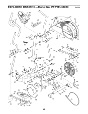
EXPLODED DRAWING-Model No. PFEVEL33020 R0802A 23 63 8 64 24 29 52 52 52 52 4 6 55 46 49 50 56 5 45 59 44 48 38 47 49 33 65 22 41 59 45 47 49 38 55 56 46 49 50 3 52 52 52 64 48 2 5 40 14 40 59 27 60 59 60 17 33 58 39 57 12 35 38 51 36 16 37 37 36 51 15 22 60 41 21 28 34 21 10 52 33 53 54 61 13 51 51 40 39 26 7 33 25 5442 38 31 32 30 31 30 33 1 62 16 33 61 9 34 51 51 18 52 20 51 20 11 15 19 40 36 37 38 35 36 15
EXPLODED DRAWING-Model No. PFEVEL33020 R0802A 23 63 8 64 24 29 52 52 52 52 4 6 55 46 49 50 56 5 45 59 44 48 38 47 49 33 65 22 41 59 45 47 49 38 55 56 46 49 50 3 52 52 52 64 48 2 5 40 14 40 59 27 60 59 60 17 33 58 39 57 12 35 38 51 36 16 37 37 36 51 15 22 60 41 21 28 34 21 10 52 33 53 54 61 13 51 51 40 39 26 7 33 25 5442 38 31 32 30 31 30 33 1 62 16 33 61 9 34 51 51 18 52 20 51 20 11 15 19 40 36 37 38 35 36 15

Uk Manual
Page 16
... prepared to give the following information: • the MODEL NUMBER of the product (PFEVEL33020) • the NAME of the product (PROFORM® 660 XT elliptical trainer) • the SERIAL NUMBER of the product (see the front cover of this manual) • the KEY NUMBER and DESCRIPTION of the part(s) (see page 14 of this manual) PROFORM is a registered trademark of ICON Health & Fitness, Inc. ORDERING REPLACEMENT PARTS To order replacement parts, contact the ICON Health & Fitness, Ltd.
... prepared to give the following information: • the MODEL NUMBER of the product (PFEVEL33020) • the NAME of the product (PROFORM® 660 XT elliptical trainer) • the SERIAL NUMBER of the product (see the front cover of this manual) • the KEY NUMBER and DESCRIPTION of the part(s) (see page 14 of this manual) PROFORM is a registered trademark of ICON Health & Fitness, Inc. ORDERING REPLACEMENT PARTS To order replacement parts, contact the ICON Health & Fitness, Ltd.

