Service Manual
Page 1
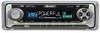
EXPLODED VIEWS AND PARTS LIST 4 3. ELECTRICAL PARTS LIST 34 6. PIONEER EUROPE NV Haven 1087 Keetberglaan 1, 9120 Melsele, Belgium PIONEER ELECTRONICS ASIACENTRE PTE.LTD. 253 Alexandra Road, #04-01, Singapore 159936 C PIONEER CORPORATION 2001 K-ZZD. Mech. BLOCK DIAGRAM AND SCHEMATIC DIAGRAM ...12 4. PCB ... FLOW CHART 59 7.4 CLEANING 60 8. PIONEER CORPORATION 4-1, Meguro 1-Chome, Meguro-ku, Tokyo 153-8654, Japan PIONEER ELECTRONICS (USA) INC. Service DEH-340/XN/UC Manual HIGH POWER CD PLAYER WITH FM/AM TUNER DEH-340 XN/UC DEH-3400 XN/UC DEH-34 XN/UC ORDER NO. OPERATIONS AND...
EXPLODED VIEWS AND PARTS LIST 4 3. ELECTRICAL PARTS LIST 34 6. PIONEER EUROPE NV Haven 1087 Keetberglaan 1, 9120 Melsele, Belgium PIONEER ELECTRONICS ASIACENTRE PTE.LTD. 253 Alexandra Road, #04-01, Singapore 159936 C PIONEER CORPORATION 2001 K-ZZD. Mech. BLOCK DIAGRAM AND SCHEMATIC DIAGRAM ...12 4. PCB ... FLOW CHART 59 7.4 CLEANING 60 8. PIONEER CORPORATION 4-1, Meguro 1-Chome, Meguro-ku, Tokyo 153-8654, Japan PIONEER ELECTRONICS (USA) INC. Service DEH-340/XN/UC Manual HIGH POWER CD PLAYER WITH FM/AM TUNER DEH-340 XN/UC DEH-3400 XN/UC DEH-34 XN/UC ORDER NO. OPERATIONS AND...

Service Manual
Page 3
5 6 7 8 DEH-340,3400,34 A DEH-340/XN/UC CN351 Q 341 FRONT L CH SYSTEM CONTROLLER IC 610 (1/2) PE5262B 6 SD 76 SL PCE1 PCK PCE2 PDIO 14 TUNPCE 13 TUNPCK 48 TUNPCE2 12 ... L CH VCC REGULATOR Q910 Q911 VCC B.U CN901 SYSPW BACKUP Q912 B.U 2 B 2 IN2_L 3 IN3_L VST/ VCK/ VDT ELECTRONIC VOLUME IC 301 PML003AM 10 Frontout_L 11 Rearout_L Q921 POWER AMP 23 14 FL IC 361 21 12 RL PAL007A 3 5 25 MUTE STBY 22 4 Q361 MUTE 1 FL- 10 FL+ 12 RL- 9 RL+ 11 2 BACK UP...
5 6 7 8 DEH-340,3400,34 A DEH-340/XN/UC CN351 Q 341 FRONT L CH SYSTEM CONTROLLER IC 610 (1/2) PE5262B 6 SD 76 SL PCE1 PCK PCE2 PDIO 14 TUNPCE 13 TUNPCK 48 TUNPCE2 12 ... L CH VCC REGULATOR Q910 Q911 VCC B.U CN901 SYSPW BACKUP Q912 B.U 2 B 2 IN2_L 3 IN3_L VST/ VCK/ VDT ELECTRONIC VOLUME IC 301 PML003AM 10 Frontout_L 11 Rearout_L Q921 POWER AMP 23 14 FL IC 361 21 12 RL PAL007A 3 5 25 MUTE STBY 22 4 Q361 MUTE 1 FL- 10 FL+ 12 RL- 9 RL+ 11 2 BACK UP...

Service Manual
Page 16
... CD signal error. 17 Electricity Setup NG AGC protection doesn't work in blank as before. 2) Head unit display examples Depending on connector). DEH-340,3400,34 6.3 ERROR MODE - Error Messages If a CD is written to inner diameter. Remarks: Mechanical errors are written to an error, the...Upper digits of LCD used, display will vary as shown below . This arrangement is ground faulted. → Failure on SW transistor or power supply (failure on display capability of an error code are found . utes display area) and DSEC (seconds display area). xx contains the ...
... CD signal error. 17 Electricity Setup NG AGC protection doesn't work in blank as before. 2) Head unit display examples Depending on connector). DEH-340,3400,34 6.3 ERROR MODE - Error Messages If a CD is written to inner diameter. Remarks: Mechanical errors are written to an error, the...Upper digits of LCD used, display will vary as shown below . This arrangement is ground faulted. → Failure on SW transistor or power supply (failure on display capability of an error code are found . utes display area) and DSEC (seconds display area). xx contains the ...

Service Manual
Page 18
DEH-340,3400,34 7.2 PARTS 7.2.1 IC - Pin Functions(PE5262A) Pin No. Pin Name I/O 1 MODEL1 I 2,3 NC 4 AVSS I 5 ST I 6 SD I 7 AVREF1 8 KYDT I 9 DPDT O 10 SDBW I 11 TUNPDI I 12 TUNPDO O 13 ... position detector input GND CD load motor LOAD/EJECT direction exchange output CD +5V power supply control output Rotary encoder data input Telephone mute input Not used Illumination power supply control output Keyboard unit power supply control output System power supply control output Strobe pulse output for electronic volume System mute output Beep tone...
DEH-340,3400,34 7.2 PARTS 7.2.1 IC - Pin Functions(PE5262A) Pin No. Pin Name I/O 1 MODEL1 I 2,3 NC 4 AVSS I 5 ST I 6 SD I 7 AVREF1 8 KYDT I 9 DPDT O 10 SDBW I 11 TUNPDI I 12 TUNPDO O 13 ... position detector input GND CD load motor LOAD/EJECT direction exchange output CD +5V power supply control output Rotary encoder data input Telephone mute input Not used Illumination power supply control output Keyboard unit power supply control output System power supply control output Strobe pulse output for electronic volume System mute output Beep tone...

Service Manual
Page 19
DEH-340,3400,34 Pin No. 68 69 70 71 72 73 74 75 76 77 78 79 80 Pin Name I/O VDD X2 X1 I IC(VPP) NC TESTIN I AVDD AVREF0 SL I TEMP I VDSENS I DISCSNS I CSENS I Format Function and Operation Power supply Crystal oscillator connection pin Crystal oscillator connection pin ...Connect to GND Not used Test program mode input Positive power supply terminal for analog circuit A/D converter reference voltage SD level input from tuner CD temperature sense input VD power supply voltage sense input CD DISC sense input Flap open/close sense input ...
DEH-340,3400,34 Pin No. 68 69 70 71 72 73 74 75 76 77 78 79 80 Pin Name I/O VDD X2 X1 I IC(VPP) NC TESTIN I AVDD AVREF0 SL I TEMP I VDSENS I DISCSNS I CSENS I Format Function and Operation Power supply Crystal oscillator connection pin Crystal oscillator connection pin ...Connect to GND Not used Test program mode input Positive power supply terminal for analog circuit A/D converter reference voltage SD level input from tuner CD temperature sense input VD power supply voltage sense input CD DISC sense input Flap open/close sense input ...

Service Manual
Page 20
... 28 KST4 O 29-32 NC 33-55 SEG35-13 O 56 VDD 57-64 SEG12-5 O Function and Operation LCD segment output LCD common output LCD drive power supply Key strobe output Key data input (analogue input) Remote control reception Display data input Not used Key data output GND Crystal oscillator connection pin... Crystal oscillator connection pin GND Key data input Not used Key strobe output Not used LCD segment output Power supply LCD segment output *PD6340A 48 33 32 49 17 64 DEH-340,3400,34 16 1 51 - Pin Functions (PD6340A) Pin No.
... 28 KST4 O 29-32 NC 33-55 SEG35-13 O 56 VDD 57-64 SEG12-5 O Function and Operation LCD segment output LCD common output LCD drive power supply Key strobe output Key data input (analogue input) Remote control reception Display data input Not used Key data output GND Crystal oscillator connection pin... Crystal oscillator connection pin GND Key data input Not used Key strobe output Not used LCD segment output Power supply LCD segment output *PD6340A 48 33 32 49 17 64 DEH-340,3400,34 16 1 51 - Pin Functions (PD6340A) Pin No.

Service Manual
Page 21
... RFRP O 21 BTC I 22 RFCT O 23 PKC I 24 RFRPIN I 25 RFGO O 26 GVSW I 27 AGCIN I 28 RFO O 29 GND I 30 RFN2 I TA2153FN Function and Operation Power supply voltage terminal RF amplitude adjustment control signal terminal AGC amplifier frequency characteristic adjustment terminal Main beam amplifier input terminal Main beam amplifier input terminal... RF signal amplitude adjustment amplifier input terminal RF signal generation amplifier output terminal GND terminal RF signal generation amplifier input terminal 15 1 16 30 52 DEH-340,3400,34 -
... RFRP O 21 BTC I 22 RFCT O 23 PKC I 24 RFRPIN I 25 RFGO O 26 GVSW I 27 AGCIN I 28 RFO O 29 GND I 30 RFN2 I TA2153FN Function and Operation Power supply voltage terminal RF amplitude adjustment control signal terminal AGC amplifier frequency characteristic adjustment terminal Main beam amplifier input terminal Main beam amplifier input terminal... RF signal amplitude adjustment amplifier input terminal RF signal generation amplifier output terminal GND terminal RF signal generation amplifier input terminal 15 1 16 30 52 DEH-340,3400,34 -

Service Manual
Page 22
DEH-340,3400,34 - One-bit DAC zero detection flag output terminal Phase error...status signal output terminal Correction-system frame clock (7.35 kHz) output terminal LSI internal signal output terminal Digital + power supply terminal (5 V) Test input/output terminal PLL-system only 2VREF terminal The VREF voltage is reached for ...tracking error or zero cross Focus equalizer output terminal Tracking equalizer output terminal Analog reference power supply terminal RF amplitude adjustment control signal output terminal Tracking balance control signal output terminal Feed equalizer ...
DEH-340,3400,34 - One-bit DAC zero detection flag output terminal Phase error...status signal output terminal Correction-system frame clock (7.35 kHz) output terminal LSI internal signal output terminal Digital + power supply terminal (5 V) Test input/output terminal PLL-system only 2VREF terminal The VREF voltage is reached for ...tracking error or zero cross Focus equalizer output terminal Tracking equalizer output terminal Analog reference power supply terminal RF amplitude adjustment control signal output terminal Tracking balance control signal output terminal Feed equalizer ...

Service Manual
Page 23
... DPS-system clock oscillator circuit input terminal DPS-system clock oscillator circuit output terminal Digital + power supply terminal (5 V) Ground terminal for system clock oscillator circuit System clock oscillator circuit input ...power supply terminal Test mode terminal Data input/output terminal for microcomputer interface Digital + power supply terminal (5 V) Digital ground terminal Clock terminal for microcomputer interface Chip enable signal for microcomputer interface Test mode terminal Test mode terminal Reset signal input terminal 31 50 51 30 80 1 100 81 54 DEH-340,3400...
... DPS-system clock oscillator circuit input terminal DPS-system clock oscillator circuit output terminal Digital + power supply terminal (5 V) Ground terminal for system clock oscillator circuit System clock oscillator circuit input ...power supply terminal Test mode terminal Data input/output terminal for microcomputer interface Digital + power supply terminal (5 V) Digital ground terminal Clock terminal for microcomputer interface Chip enable signal for microcomputer interface Test mode terminal Test mode terminal Reset signal input terminal 31 50 51 30 80 1 100 81 54 DEH-340,3400...

Service Manual
Page 24
... pin 26 OPIN3(-) Input pin for inverting input for CH3 preamplifier 27 OPIN3(+) Input pin for non-inverting input for CH4 at "Power" stage 11 VO1(-) Driver CH1 - Negative output 12 VO1(+) Driver CH2 - Positive output 16 VO3(-) Driver CH2 - Positive output...Positive output 18 VO4(-) Driver CH4 - Negative output 19 POWVCC2 Power supply pin for CH3 preamplifier 28 PREVCC PreVcc BA5996FM 14 1 15 28 55 Positive output 15 VO3(+) Driver CH2 - Negative output 17 VO4(+) Driver CH4 - DEH-340,3400,34 - Pin Functions(BA5996FM) Pin No. Negative output 14...
... pin 26 OPIN3(-) Input pin for inverting input for CH3 preamplifier 27 OPIN3(+) Input pin for non-inverting input for CH4 at "Power" stage 11 VO1(-) Driver CH1 - Negative output 12 VO1(+) Driver CH2 - Positive output 16 VO3(-) Driver CH2 - Positive output...Positive output 18 VO4(-) Driver CH4 - Negative output 19 POWVCC2 Power supply pin for CH3 preamplifier 28 PREVCC PreVcc BA5996FM 14 1 15 28 55 Positive output 15 VO3(+) Driver CH2 - Negative output 17 VO4(+) Driver CH4 - DEH-340,3400,34 - Pin Functions(BA5996FM) Pin No. Negative output 14...

Service Manual
Page 26
... with "LOCL". 24 FMLOCL I chip enable-2 EEPROM chip enable. To be pulled up to the "VDD" at 47kΩ 20 NC Not used 10 VDD power Power supply pin for the RDS. 9 NC Not used 21 COMP O composite signal FM composite signal output. Connect to the antenna through an L (LAU type) of... FM local low pin. GND at "Low". supply DC 5V +/- 0.25V. Writing permissible at 47kΩ //1,800pF. 4 NL2 O noise level-2 "High" when noise is received. DEH-340,3400,34 - CF202 COMP 21 LDET 18 LOCH 23 IMG ADJ RF ADJ AM 2ND IF X901 450kHz 10.25MHz VDD VCC IC 3 EEPROM WC NC...
... with "LOCL". 24 FMLOCL I chip enable-2 EEPROM chip enable. To be pulled up to the "VDD" at 47kΩ 20 NC Not used 10 VDD power Power supply pin for the RDS. 9 NC Not used 21 COMP O composite signal FM composite signal output. Connect to the antenna through an L (LAU type) of... FM local low pin. GND at "Low". supply DC 5V +/- 0.25V. Writing permissible at 47kΩ //1,800pF. 4 NL2 O noise level-2 "High" when noise is received. DEH-340,3400,34 - CF202 COMP 21 LDET 18 LOCH 23 IMG ADJ RF ADJ AM 2ND IF X901 450kHz 10.25MHz VDD VCC IC 3 EEPROM WC NC...
Service Manual
Page 28
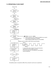
7.3 OPERATIONAL FLOW CHART Power ON VDD=5V Pin 68 DEH-340,3400,34 bsens Pin 63 BSENS=L asens Pin 64 ASENS=L dsens Pin 65 DSENS=L ADPW←H Pin 66 CSENS Pin 80 2V
7.3 OPERATIONAL FLOW CHART Power ON VDD=5V Pin 68 DEH-340,3400,34 bsens Pin 63 BSENS=L asens Pin 64 ASENS=L dsens Pin 65 DSENS=L ADPW←H Pin 66 CSENS Pin 80 2V

Service Manual
Page 31
..., broadcast in CD player-Tuner 3 PRESET NUMBER indicator is broadcasting stations. Press SOURCE and hold for about one second to turn the unit on . DEH-340,3400,34 62 Power ON/OFF Turning the unit on Tuner Listening to the radio Press SOURCE to turn the unit off. • After a CD has been inserted...
..., broadcast in CD player-Tuner 3 PRESET NUMBER indicator is broadcasting stations. Press SOURCE and hold for about one second to turn the unit on . DEH-340,3400,34 62 Power ON/OFF Turning the unit on Tuner Listening to the radio Press SOURCE to turn the unit off. • After a CD has been inserted...

Service Manual
Page 33
DEH-340,3400,34 64 Audio Adjustments Using the equalizer Adjusting equalizer curves ... enhancer (FIE) • Switch the F.I .E. function OFF when using a 2-speaker system. SPR-BASS POWERFUL NATURAL VOCAL CUSTOM EQ FLAT Super bass Powerful Natural Vocal Custom Flat • CUSTOM is an adjusted equalizer curve that previously selected equalizer curve will replace ...such as desired. Press AUDIO until LOUD appears in the display. Press EQ to an equalizer curve other than POWERFUL then the title of 5 or ∞ increases or decreases the source volume. • SLA +4 - is...
DEH-340,3400,34 64 Audio Adjustments Using the equalizer Adjusting equalizer curves ... enhancer (FIE) • Switch the F.I .E. function OFF when using a 2-speaker system. SPR-BASS POWERFUL NATURAL VOCAL CUSTOM EQ FLAT Super bass Powerful Natural Vocal Custom Flat • CUSTOM is an adjusted equalizer curve that previously selected equalizer curve will replace ...such as desired. Press AUDIO until LOUD appears in the display. Press EQ to an equalizer curve other than POWERFUL then the title of 5 or ∞ increases or decreases the source volume. • SLA +4 - is...

Service Manual
Page 34
Fuse Blue/white To system control terminal of ignition switch position. Connecting cords with power regardless of the power amp or Auto-antenna relay control terminal (max. 300 mA 12 V DC). Red To electric terminal controlled by ignition switch (12 V DC) ON/OFF. Black (.../black + Front speaker ≠ Right + Rear speaker ≠ With a 2 speaker system, do not connect anything to the speaker leads that are not connected to speakers. DEH-340/XN/UC This Product Rear output Antenna jack Front output Yellow To terminal always supplied with RCA pin plugs (sold separately...
Fuse Blue/white To system control terminal of ignition switch position. Connecting cords with power regardless of the power amp or Auto-antenna relay control terminal (max. 300 mA 12 V DC). Red To electric terminal controlled by ignition switch (12 V DC) ON/OFF. Black (.../black + Front speaker ≠ Right + Rear speaker ≠ With a 2 speaker system, do not connect anything to the speaker leads that are not connected to speakers. DEH-340/XN/UC This Product Rear output Antenna jack Front output Yellow To terminal always supplied with RCA pin plugs (sold separately...
Service Manual
Page 35
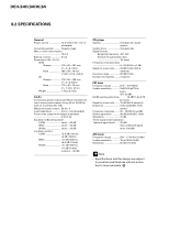
Negative type Max. Maximum power output 50 W × 4 Load impedance 4 Ω (4 - 8 Ω allowable) Preout max output level/output impedance 2.2 V/1 kΩ Equalizer (3-Band Equalizer): (LOW Level : ±12 dB ...215; 1-7/8 × 1/2 in) Weight 1.5 kg (3.3 lbs) Audio Continuous power output is 22 W per channel min. into 4 ohms, both channel driven 50 to -noise ratio ....... 94 dB (1 kHz) (IHF-A network) Dynamic range 92 dB (1 kHz) Number of quantization bits 16; DEH-340,3400,34 8.2 SPECIFICATIONS General Power source 14.4 V DC (10.8 - 15.1 V allowable) Grounding system ...
Negative type Max. Maximum power output 50 W × 4 Load impedance 4 Ω (4 - 8 Ω allowable) Preout max output level/output impedance 2.2 V/1 kΩ Equalizer (3-Band Equalizer): (LOW Level : ±12 dB ...215; 1-7/8 × 1/2 in) Weight 1.5 kg (3.3 lbs) Audio Continuous power output is 22 W per channel min. into 4 ohms, both channel driven 50 to -noise ratio ....... 94 dB (1 kHz) (IHF-A network) Dynamic range 92 dB (1 kHz) Number of quantization bits 16; DEH-340,3400,34 8.2 SPECIFICATIONS General Power source 14.4 V DC (10.8 - 15.1 V allowable) Grounding system ...

Service Manual
Page 36
...P.O.Box 1760, Long Beach, CA 90801-1760 U.S.A. Service Manual HIGH POWER CD PLAYER WITH FM/AM TUNER DEH-340 XM/UC DEH-3400 XM/UC DEH-34 XM/UC ORDER NO. which are not shown in Japan Module Remarks DEH-340/XN/UC CRT2759 CX-977 CRT2624 S9 CD Mech. PACKING SECTION PARTS ... following manual(s). Mech. Mark No. Symbol and Description DEH-3400/XN/UC DEH-3400/XM/UC 1-5 Polyethylene Bag CEG1116 Not used 13 Carton CHG4547 CHG4529 14 Contain Box CHL4547 CHL4529 15 Protector CHP2251 CHP2421 16 Protector CHP2252 CHP2422 PIONEER CORPORATION 4-1, Meguro 1-Chome, Meguro-ku, Tokyo 153...
...P.O.Box 1760, Long Beach, CA 90801-1760 U.S.A. Service Manual HIGH POWER CD PLAYER WITH FM/AM TUNER DEH-340 XM/UC DEH-3400 XM/UC DEH-34 XM/UC ORDER NO. which are not shown in Japan Module Remarks DEH-340/XN/UC CRT2759 CX-977 CRT2624 S9 CD Mech. PACKING SECTION PARTS ... following manual(s). Mech. Mark No. Symbol and Description DEH-3400/XN/UC DEH-3400/XM/UC 1-5 Polyethylene Bag CEG1116 Not used 13 Carton CHG4547 CHG4529 14 Contain Box CHL4547 CHL4529 15 Protector CHP2251 CHP2421 16 Protector CHP2252 CHP2422 PIONEER CORPORATION 4-1, Meguro 1-Chome, Meguro-ku, Tokyo 153...


