
Service Manual
Page 18
DEH-340,3400,34 7.2 PARTS 7.2.1 IC - Pin Functions(PE5262A) Pin No. Pin Name I/O 1 MODEL1 I 2,3 NC 4 AVSS I 5 ST I 6 SD I 7 AVREF1 8... Servo driver power supply control output CD LSI chip enable output CD LSI reset output CD LSI clock output CD LSI data input/output Driver input select output Home position detector input GND CD load ...electronic volume System mute output Beep tone output Local H output Not used EEPROM chip enable output Clock adjustment output Clock output for electronic volume Data output for electronic volume Antenna output Eject key input pin Stand-by...
DEH-340,3400,34 7.2 PARTS 7.2.1 IC - Pin Functions(PE5262A) Pin No. Pin Name I/O 1 MODEL1 I 2,3 NC 4 AVSS I 5 ST I 6 SD I 7 AVREF1 8... Servo driver power supply control output CD LSI chip enable output CD LSI reset output CD LSI clock output CD LSI data input/output Driver input select output Home position detector input GND CD load ...electronic volume System mute output Beep tone output Local H output Not used EEPROM chip enable output Clock adjustment output Clock output for electronic volume Data output for electronic volume Antenna output Eject key input pin Stand-by...

Service Manual
Page 22
... data output terminal Digital out output terminal Buffer memory over signal output terminal Correction flag output terminal CRCC decision result output for sub code Q data Clock input/output terminal for sub code P-W data read Digital + power supply terminal (5 V) Digital ground terminal Sub code P-W data output terminal Replay-system frame sync signal... Speed error signal or feed search EQ output Disc equalizer output terminal Analog reference power supply terminal APC circuit ON/OFF signal output terminal 53 DEH-340,3400,34 -
... data output terminal Digital out output terminal Buffer memory over signal output terminal Correction flag output terminal CRCC decision result output for sub code Q data Clock input/output terminal for sub code P-W data read Digital + power supply terminal (5 V) Digital ground terminal Sub code P-W data output terminal Replay-system frame sync signal... Speed error signal or feed search EQ output Disc equalizer output terminal Analog reference power supply terminal APC circuit ON/OFF signal output terminal 53 DEH-340,3400,34 -

Service Manual
Page 23
...DPS-system clock oscillator circuit input terminal DPS-system clock oscillator circuit output terminal Digital + power supply terminal (5 V) Ground terminal for system clock oscillator circuit System clock oscillator circuit input terminal System clock oscillator circuit output terminal For system clock oscillator circuit...mode terminal Data input/output terminal for microcomputer interface Digital + power supply terminal (5 V) Digital ground terminal Clock terminal for microcomputer interface Chip enable signal for microcomputer interface Test mode terminal Test mode terminal Reset signal input...
...DPS-system clock oscillator circuit input terminal DPS-system clock oscillator circuit output terminal Digital + power supply terminal (5 V) Ground terminal for system clock oscillator circuit System clock oscillator circuit input terminal System clock oscillator circuit output terminal For system clock oscillator circuit...mode terminal Data input/output terminal for microcomputer interface Digital + power supply terminal (5 V) Digital ground terminal Clock terminal for microcomputer interface Chip enable signal for microcomputer interface Test mode terminal Test mode terminal Reset signal input...

Service Manual
Page 26
... Ω //4,700pF) 14 DI/DO I/O data input/ Data input/Data output data output To be pulled up to the "VDD" at 47kΩ 15 CK I clock Clock input To be pulled up to the "VDD" at 47kΩ 16 CE1 I current request Active at 47kΩ 19 CREQ I chip enable-1 AF·...; 20 NC Not used 10 VDD power Power supply pin for the digital section. 12 CE2 I /O signal level Received FM/AM signal level (strength) output. DEH-340,3400,34 - To be pulled up to 2.2kΩ) between the GND. 57 Normally open in use, do not drive it open . 8 SDBW O SD bandwidth SD...
... Ω //4,700pF) 14 DI/DO I/O data input/ Data input/Data output data output To be pulled up to the "VDD" at 47kΩ 15 CK I clock Clock input To be pulled up to the "VDD" at 47kΩ 16 CE1 I current request Active at 47kΩ 19 CREQ I chip enable-1 AF·...; 20 NC Not used 10 VDD power Power supply pin for the digital section. 12 CE2 I /O signal level Received FM/AM signal level (strength) output. DEH-340,3400,34 - To be pulled up to 2.2kΩ) between the GND. 57 Normally open in use, do not drive it open . 8 SDBW O SD bandwidth SD...
Service Manual
Page 30
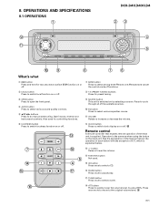
... quality controls. 5 5/∞/2/3 buttons Press to switch local function on or off . 8. See the explanation of the head unit is explained below. # +/- DEH-340,3400,34 23 4 5 09 8 76 What's what 1 BSM button Press and hold for two seconds to switch BSM function on or off. 7 BAND button ...to select a CD. ^ PAUSE button Press once to pause play. & TUNER button Press once to select a tuner. ^ * ATT button Press to switch clock display on or off . 8 1-6 (PRESET TUNING) buttons Press for controlling functions. 9 SOURCE button This unit is the same as when using the button ...
... quality controls. 5 5/∞/2/3 buttons Press to switch local function on or off . 8. See the explanation of the head unit is explained below. # +/- DEH-340,3400,34 23 4 5 09 8 76 What's what 1 BSM button Press and hold for two seconds to switch BSM function on or off. 7 BAND button ...to select a CD. ^ PAUSE button Press once to pause play. & TUNER button Press once to select a tuner. ^ * ATT button Press to switch clock display on or off . 8 1-6 (PRESET TUNING) buttons Press for controlling functions. 9 SOURCE button This unit is the same as when using the button ...


