
Owner's Manual
Page 3
... conversation, quiet office 60 Air conditioner at 20 feet, sewing machine 70 Vacuum cleaner, hair dryer, noisy restaurant 80 Average city traffic, garbage disposals, alarm clock at a safe level. En 2 Italiano Nederlands To establish a safe level: • Start your volume control at a safe level BEFORE your new sound equipment will help...
... conversation, quiet office 60 Air conditioner at 20 feet, sewing machine 70 Vacuum cleaner, hair dryer, noisy restaurant 80 Average city traffic, garbage disposals, alarm clock at a safe level. En 2 Italiano Nederlands To establish a safe level: • Start your volume control at a safe level BEFORE your new sound equipment will help...

Owner's Manual
Page 7
... search controls. Also used for controlling functions. 6 LOUDNESS button Press to select various equalizer curves. - VOLUME Rotate to increase or decrease the volume. = CLOCK button Press to switch clock display on or off . 7 BAND button Press to select among three FM and one AM band and cancel the control mode of the...
... search controls. Also used for controlling functions. 6 LOUDNESS button Press to select various equalizer curves. - VOLUME Rotate to increase or decrease the volume. = CLOCK button Press to switch clock display on or off . 7 BAND button Press to select among three FM and one AM band and cancel the control mode of the...

Owner's Manual
Page 16
...AUDIO until TIME appears in the display. 3 Select the portion of the time display you select portions of the clock display the portion selected will blink. Each press of the clock display: HOUR-MINUTE As you wish to select the time display. Pressing 5 will decrease the selected hour or minute...or minute. Other Functions Setting the time This is displayed again after 25 seconds. 4 Select the correct time with 2/3. Press CLOCK to set the time on the unit's clock display. 1 Press SOURCE and hold until the unit turns off. 2 Press AUDIO and hold until the unit turns off. 15...
...AUDIO until TIME appears in the display. 3 Select the portion of the time display you select portions of the clock display the portion selected will blink. Each press of the clock display: HOUR-MINUTE As you wish to select the time display. Pressing 5 will decrease the selected hour or minute...or minute. Other Functions Setting the time This is displayed again after 25 seconds. 4 Select the correct time with 2/3. Press CLOCK to set the time on the unit's clock display. 1 Press SOURCE and hold until the unit turns off. 2 Press AUDIO and hold until the unit turns off. 15...

Service Manual
Page 18
... Strobe pulse output for electronic volume System mute output Beep tone output Local H output Not used EEPROM chip enable output Clock adjustment output Clock output for electronic volume Data output for electronic volume Antenna output Eject key input pin Stand-by output Not used Reset ...input Not used Back up power sense input ACC power sense input Grille detach sense A/D converter power supply output Not used 49 Pin Functions(PE5262A) Pin No. DEH-340...
... Strobe pulse output for electronic volume System mute output Beep tone output Local H output Not used EEPROM chip enable output Clock adjustment output Clock output for electronic volume Data output for electronic volume Antenna output Eject key input pin Stand-by output Not used Reset ...input Not used Back up power sense input ACC power sense input Grille detach sense A/D converter power supply output Not used 49 Pin Functions(PE5262A) Pin No. DEH-340...

Service Manual
Page 22
... data output terminal Digital out output terminal Buffer memory over signal output terminal Correction flag output terminal CRCC decision result output for sub code Q data Clock input/output terminal for sub code P-W data read Digital + power supply terminal (5 V) Digital ground terminal Sub code P-W data output terminal Replay-system frame sync signal... Speed error signal or feed search EQ output Disc equalizer output terminal Analog reference power supply terminal APC circuit ON/OFF signal output terminal 53 DEH-340,3400,34 -
... data output terminal Digital out output terminal Buffer memory over signal output terminal Correction flag output terminal CRCC decision result output for sub code Q data Clock input/output terminal for sub code P-W data read Digital + power supply terminal (5 V) Digital ground terminal Sub code P-W data output terminal Replay-system frame sync signal... Speed error signal or feed search EQ output Disc equalizer output terminal Analog reference power supply terminal APC circuit ON/OFF signal output terminal 53 DEH-340,3400,34 -

Service Manual
Page 23
DEH-340,3400,34 Pin No. Pin Name I/O 58-61 FLGA-D O 62 VDD 63 VSS 64 IO0 O 65 IO1 O 66 IO2 I 67 IO3 O 68 dmout I 69 ckse I ... output terminal L channel D/A converting unit power supply terminal Test mode terminal Data input/output terminal for microcomputer interface Digital + power supply terminal (5 V) Digital ground terminal Clock terminal for microcomputer interface Chip enable signal for microcomputer interface Test mode terminal Test mode terminal Reset signal input terminal 31 50 51 30 80...
DEH-340,3400,34 Pin No. Pin Name I/O 58-61 FLGA-D O 62 VDD 63 VSS 64 IO0 O 65 IO1 O 66 IO2 I 67 IO3 O 68 dmout I 69 ckse I ... output terminal L channel D/A converting unit power supply terminal Test mode terminal Data input/output terminal for microcomputer interface Digital + power supply terminal (5 V) Digital ground terminal Clock terminal for microcomputer interface Chip enable signal for microcomputer interface Test mode terminal Test mode terminal Reset signal input terminal 31 50 51 30 80...

Service Manual
Page 26
... Ω //4,700pF) 14 DI/DO I/O data input/ Data input/Data output data output To be pulled up to the "VDD" at 47kΩ 15 CK I clock Clock input To be pulled up to the "VDD" at 47kΩ 20 NC Not used when taking diver FIX trigger from here and "High: 0.9VDD... the FMLOCL is necessary. 28 AMANT I FM antenna input FM antenna input. 75Ω. To be pulled up to the base of the NPN transistor. DEH-340,3400,34 - CF202 COMP 21 LDET 18 LOCH 23 IMG ADJ RF ADJ AM 2ND IF X901 450kHz 10.25MHz VDD VCC IC 3 EEPROM WC...
... Ω //4,700pF) 14 DI/DO I/O data input/ Data input/Data output data output To be pulled up to the "VDD" at 47kΩ 15 CK I clock Clock input To be pulled up to the "VDD" at 47kΩ 20 NC Not used when taking diver FIX trigger from here and "High: 0.9VDD... the FMLOCL is necessary. 28 AMANT I FM antenna input FM antenna input. 75Ω. To be pulled up to the base of the NPN transistor. DEH-340,3400,34 - CF202 COMP 21 LDET 18 LOCH 23 IMG ADJ RF ADJ AM 2ND IF X901 450kHz 10.25MHz VDD VCC IC 3 EEPROM WC...
Service Manual
Page 30
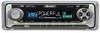
...OPEN button Press to open the front panel. 4 AUDIO button Press to select various sound quality controls. 5 5/∞/2/3 buttons Press to switch clock display on or off . Press once more to return to quickly lower the volume level, by selecting a source. OPERATIONS AND SPECIFICATIONS 8.1 OPERATIONS ...volume. 6 LOUDNESS button Press to switch loudness function on or off. # 7 * @ CLOCK button Press to do manual seek tuning, fast forward, reverse and track search controls. Operation is explained below. # +/- DEH-340,3400,34 23 4 5 09 8 76 What's what 1 BSM button Press and hold ...
...OPEN button Press to open the front panel. 4 AUDIO button Press to select various sound quality controls. 5 5/∞/2/3 buttons Press to switch clock display on or off . Press once more to return to quickly lower the volume level, by selecting a source. OPERATIONS AND SPECIFICATIONS 8.1 OPERATIONS ...volume. 6 LOUDNESS button Press to switch loudness function on or off. # 7 * @ CLOCK button Press to do manual seek tuning, fast forward, reverse and track search controls. Operation is explained below. # +/- DEH-340,3400,34 23 4 5 09 8 76 What's what 1 BSM button Press and hold ...

