Service Manual
Page 1
...1760 U.S.A. NOV. 2001 Printed in Japan BLOCK DIAGRAM AND SCHEMATIC DIAGRAM ...12 4. ADJUSTMENT 41 7. PIONEER EUROPE NV Haven 1087 Keetberglaan 1, 9120 Melsele, Belgium PIONEER ELECTRONICS ASIACENTRE PTE.LTD. 253 Alexandra Road, #04-01, Singapore 159936 C PIONEER CORPORATION 2001 K-ZZD. EXPLODED VIEWS AND PARTS...PIONEER ELECTRONICS (USA) INC. Order No. This service manual should be used together with the following manual(s): Model No. ELECTRICAL PARTS LIST 34 6. Service DEH-340/XN/UC Manual HIGH POWER CD PLAYER WITH FM/AM TUNER DEH-340 XN/UC DEH-3400 XN/UC DEH...
...1760 U.S.A. NOV. 2001 Printed in Japan BLOCK DIAGRAM AND SCHEMATIC DIAGRAM ...12 4. ADJUSTMENT 41 7. PIONEER EUROPE NV Haven 1087 Keetberglaan 1, 9120 Melsele, Belgium PIONEER ELECTRONICS ASIACENTRE PTE.LTD. 253 Alexandra Road, #04-01, Singapore 159936 C PIONEER CORPORATION 2001 K-ZZD. EXPLODED VIEWS AND PARTS...PIONEER ELECTRONICS (USA) INC. Order No. This service manual should be used together with the following manual(s): Model No. ELECTRICAL PARTS LIST 34 6. Service DEH-340/XN/UC Manual HIGH POWER CD PLAYER WITH FM/AM TUNER DEH-340 XN/UC DEH-3400 XN/UC DEH...
Service Manual
Page 4
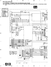
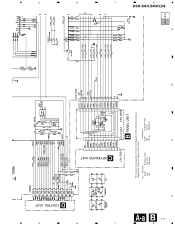
... expressed in codes: A B 14 Ex. *Resistors Code Practical value 123 12k ohms 103 10k ohms *Capacitors Code Practical value 103 0.01uF 101/10 100uF/10V 1 2 3 4 A A 1 2 3 4 DEH-340,3400,34 3.2 OVERALL CONNECTION DIAGRAM(GUIDE PAGE) Note: When ordering service parts, be sure to refer to "EXPLODED VIEWS AND PARTS LIST" or "ELECTRICAL PARTS LIST".
... expressed in codes: A B 14 Ex. *Resistors Code Practical value 123 12k ohms 103 10k ohms *Capacitors Code Practical value 103 0.01uF 101/10 100uF/10V 1 2 3 4 A A 1 2 3 4 DEH-340,3400,34 3.2 OVERALL CONNECTION DIAGRAM(GUIDE PAGE) Note: When ordering service parts, be sure to refer to "EXPLODED VIEWS AND PARTS LIST" or "ELECTRICAL PARTS LIST".
Service Manual
Page 7
8 7 6 5 A-a AB 17 CONTROL UNIT D KEYBOARD UNIT C D EJECT B PANEL UNIT For resistors and capacitors in the circuit diagrams, their resistance values or capacitance values are expressed in codes: Ex. *Resistors Code Practical value 123 12k ohms 103 10k ohms *Capacitors Code Practical value 103 0.01uF 101/10 100uF/10V C B 104 393 A- A 2 3 DSENS 4 5 6 7 A-a A-b DEH-340,3400,34 8 7 6 5
8 7 6 5 A-a AB 17 CONTROL UNIT D KEYBOARD UNIT C D EJECT B PANEL UNIT For resistors and capacitors in the circuit diagrams, their resistance values or capacitance values are expressed in codes: Ex. *Resistors Code Practical value 123 12k ohms 103 10k ohms *Capacitors Code Practical value 103 0.01uF 101/10 100uF/10V C B 104 393 A- A 2 3 DSENS 4 5 6 7 A-a A-b DEH-340,3400,34 8 7 6 5
Service Manual
Page 14
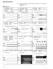
... "Source On" 0 CH1:TE 8 CH2:FE 500mV/div. 500mV/div. 200ms/div. The encircled numbers denote measuring pointes in the circuit diagram. 2. Ref. : VREF Mode : Normal 7 CH1:MD 500mV/div. DEH-340,3400,34 - Magnified drawing for "time" 8 CH1:FE 9 CH2:FOON 500mV/div. 5V/div. 500ms/div. When loading (8 cm CD) 5 CH1...
... "Source On" 0 CH1:TE 8 CH2:FE 500mV/div. 500mV/div. 200ms/div. The encircled numbers denote measuring pointes in the circuit diagram. 2. Ref. : VREF Mode : Normal 7 CH1:MD 500mV/div. DEH-340,3400,34 - Magnified drawing for "time" 8 CH1:FE 9 CH2:FOON 500mV/div. 5V/div. 500ms/div. When loading (8 cm CD) 5 CH1...


