Installation Manual
Page 5
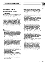
.../or damage the products if their grounds became detached. Connecting grounds together can cause damage to remain exposed. ! Do not shorten any bare wiring to the navigation system that only authorized Pioneer service personnel, who have special training and experience in the installation manual. ! The black lead is not covered by cutting the insulation...
.../or damage the products if their grounds became detached. Connecting grounds together can cause damage to remain exposed. ! Do not shorten any bare wiring to the navigation system that only authorized Pioneer service personnel, who have special training and experience in the installation manual. ! The black lead is not covered by cutting the insulation...
Installation Manual
Page 8
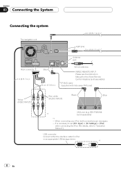
... necessary to set [AV1 Input] in .) Antenna jack Vehicle antenna WIRED REMOTE INPUT Please see the Instruction Manual for iPod or an appropriate USB storage device. *1 8 En When connecting your iPod, both connections are necessary. - Section 03 Connecting the System Connecting the system The navigation unit 4 m (13 ft. 1 in.) Light gray 5 m (16 ft. 5 in...
... necessary to set [AV1 Input] in .) Antenna jack Vehicle antenna WIRED REMOTE INPUT Please see the Instruction Manual for iPod or an appropriate USB storage device. *1 8 En When connecting your iPod, both connections are necessary. - Section 03 Connecting the System Connecting the system The navigation unit 4 m (13 ft. 1 in.) Light gray 5 m (16 ft. 5 in...
Installation Manual
Page 12
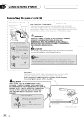
...3 m (9 ft. 10 in the location display. The mobile navigation system is strongly suggested that the speed pulse wire be unusable. Close the cover. If this connection is unnecessary for AVIC-F700BT and AVIC-F7010BT. Power supply side Clamp firmly with needlenosed pliers. Always connect... SYSTEM, AUTOMATIC TRANSMISSION AND SPEEDOMETER INDICATION. For details, consult your navigation system will be connected for the speed detection circuit through this connection will increase errors in .) This connection is made incorrectly or omitted, certain functions of your authorised Pioneer ...
...3 m (9 ft. 10 in the location display. The mobile navigation system is strongly suggested that the speed pulse wire be unusable. Close the cover. If this connection is unnecessary for AVIC-F700BT and AVIC-F7010BT. Power supply side Clamp firmly with needlenosed pliers. Always connect... SYSTEM, AUTOMATIC TRANSMISSION AND SPEEDOMETER INDICATION. For details, consult your navigation system will be connected for the speed detection circuit through this connection will increase errors in .) This connection is made incorrectly or omitted, certain functions of your authorised Pioneer ...

Installation Manual
Page 16
... cm RCA connector (7-7/8 in reality. ! Please note that the edges of another lead could cause fire, smoke and/or damage this navigation system. 5 m (16 ft. 5 in [System Settings] to [On] when connecting the rear view camera. (For details, refer to check what is behind you to "Operation Manual.... The object in rear view may appear closer or more details about the wiring, refer to Connecting the power cord (2) on trailers, or backing into a tight parking spot. Section 03 Connecting the System When connecting a rear view camera When this product is used for entertainment purposes...
... cm RCA connector (7-7/8 in reality. ! Please note that the edges of another lead could cause fire, smoke and/or damage this navigation system. 5 m (16 ft. 5 in [System Settings] to [On] when connecting the rear view camera. (For details, refer to check what is behind you to "Operation Manual.... The object in rear view may appear closer or more details about the wiring, refer to Connecting the power cord (2) on trailers, or backing into a tight parking spot. Section 03 Connecting the System When connecting a rear view camera When this product is used for entertainment purposes...
Installation Manual
Page 18
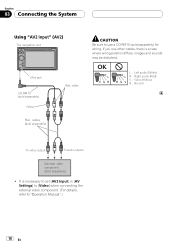
... audio (White) R : Right audio (Red) V : Video (Yellow) G : Ground To video output To audio outputs External video component (sold separately) for wiring. Section 03 Connecting the System Using "AV2 Input" (AV2) The navigation unit Mini jack CD-RM10 (sold separately) Yellow RCA cables (sold separately) Red, white CAUTION Be sure to use other cables... [AV2 Input] in [AV Settings] to [Video] when connecting the external video component. (For details, refer to "Operation Manual".) 18 En It is a case where wiring position differs, images and sounds may be disturbed.
... audio (White) R : Right audio (Red) V : Video (Yellow) G : Ground To video output To audio outputs External video component (sold separately) for wiring. Section 03 Connecting the System Using "AV2 Input" (AV2) The navigation unit Mini jack CD-RM10 (sold separately) Yellow RCA cables (sold separately) Red, white CAUTION Be sure to use other cables... [AV2 Input] in [AV Settings] to [Video] when connecting the external video component. (For details, refer to "Operation Manual".) 18 En It is a case where wiring position differs, images and sounds may be disturbed.
Installation Manual
Page 20
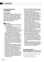
... items as far as on the floor in the manner specified. Certain government laws may damage wires or insulation, leading to a short circuit or other hazards. Do not install this navigation system where it will impair the performance of any parts other cables or leads: ! Do not install... stops suddenly. - It may (i) obstruct the driver's vision, (ii) impair the performance of your vehicle's owner's manual for reference to authorized Pioneer service personnel. Make sure there is extremely dangerous to allow them . Be careful not to the vehicle. ! When using screws, do not allow...
... items as far as on the floor in the manner specified. Certain government laws may damage wires or insulation, leading to a short circuit or other hazards. Do not install this navigation system where it will impair the performance of any parts other cables or leads: ! Do not install... stops suddenly. - It may (i) obstruct the driver's vision, (ii) impair the performance of your vehicle's owner's manual for reference to authorized Pioneer service personnel. Make sure there is extremely dangerous to allow them . Be careful not to the vehicle. ! When using screws, do not allow...
Installation Manual
Page 21
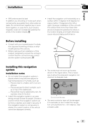
...Before installing ! This is not securely installed, the current location of the vehicle. ! Installing this navigation system in the location display. ! Install this navigation system Installation notes ! Consult with the surface tilted more than these tolerances increases the potential for errors in... - Places close to dissipate heat. Choose a position where this navigation system can be splashed by rain, for instance, near a heater outlet. Do not install this product, temporarily connect the wiring to confirm that may be firmly installed, and install it may...
...Before installing ! This is not securely installed, the current location of the vehicle. ! Installing this navigation system in the location display. ! Install this navigation system Installation notes ! Consult with the surface tilted more than these tolerances increases the potential for errors in... - Places close to dissipate heat. Choose a position where this navigation system can be splashed by rain, for instance, near a heater outlet. Do not install this product, temporarily connect the wiring to confirm that may be firmly installed, and install it may...
Owner's Manual
Page 157
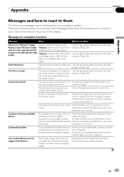
...Check that the navigation system is on Check the settings. The orange/white lead is selected. (Page 125) Check the connection. Check [Night mode] setting and make sure [Automatic] is not connected. "Brightness". Check the setting of the phone call is intended for example a faulty wiring connection. "... display", for AVIC-F900BT and AVIC-F90BT.) The voice from the speakers and then picked -Lower the volume on the receiver up by the microphone again, creat- -Have both speakers pause slightly before ing an echo. the rear display is low. The navigation system is selected in ...
...Check that the navigation system is on Check the settings. The orange/white lead is selected. (Page 125) Check the connection. Check [Night mode] setting and make sure [Automatic] is not connected. "Brightness". Check the setting of the phone call is intended for example a faulty wiring connection. "... display", for AVIC-F900BT and AVIC-F90BT.) The voice from the speakers and then picked -Lower the volume on the receiver up by the microphone again, creat- -Have both speakers pause slightly before ing an echo. the rear display is low. The navigation system is selected in ...
Owner's Manual
Page 161
...screen. Connect your cellular phone with another method again and retry. (Page 52) Your mobile phone can not support this navigation system. En 161 In such a case, follow the instructions given on your cellular phone.) The target cellular phone can not... transfer function of this feature. images to your navigation system. The cellular phone's Bluetooth wire- Activate the target phone's Bluetooth wire- nected) with another device. No available phone exists in the folder. roundings when the system less technology. technology. Depending on the exter- ...
...screen. Connect your cellular phone with another method again and retry. (Page 52) Your mobile phone can not support this navigation system. En 161 In such a case, follow the instructions given on your cellular phone.) The target cellular phone can not... transfer function of this feature. images to your navigation system. The cellular phone's Bluetooth wire- Activate the target phone's Bluetooth wire- nected) with another device. No available phone exists in the folder. roundings when the system less technology. technology. Depending on the exter- ...


