Installation Manual
Page 2
...the blue lead 6 - Parts supplied 22 - Parts supplied 26 - Adjusting the microphone angle 27 After Installation After Installing this Navigation System 28 When installing the antenna outside the vehicle (on the sun visor 26 - Mounting on the body) 25 Installing the ...view camera 16 When connecting the rear display 17 - When using the screw holes on the side of the navigation unit 22 Installing the GPS antenna 23 - Installation notes 23 - Contents IMPORTANT INFORMATION ABOUT YOUR NEW NAVIGATION SYSTEM AND THIS MANUAL 3 IMPORTANT SAFEGUARDS PLEASE READ ALL OF THESE...
...the blue lead 6 - Parts supplied 22 - Parts supplied 26 - Adjusting the microphone angle 27 After Installation After Installing this Navigation System 28 When installing the antenna outside the vehicle (on the sun visor 26 - Mounting on the body) 25 Installing the ...view camera 16 When connecting the rear display 17 - When using the screw holes on the side of the navigation unit 22 Installing the GPS antenna 23 - Installation notes 23 - Contents IMPORTANT INFORMATION ABOUT YOUR NEW NAVIGATION SYSTEM AND THIS MANUAL 3 IMPORTANT SAFEGUARDS PLEASE READ ALL OF THESE...
Installation Manual
Page 3
.... In some cases, it may not be possible to aid you in any of the vehicle's operating systems of this product. The navigation features of this navigation system (or the rear view camera option if purchased) if doing so in the operation of your vehicle. ... police stations, or similar facilities in force should always take precedence over guidance given by this navigation system is not a substitute for the navigation system. ! Section 01 En 3 English Never use this navigation system to route to safely operate the vehicle. This manual explains how to install this product where it...
.... In some cases, it may not be possible to aid you in any of the vehicle's operating systems of this product. The navigation features of this navigation system (or the rear view camera option if purchased) if doing so in the operation of your vehicle. ... police stations, or similar facilities in force should always take precedence over guidance given by this navigation system is not a substitute for the navigation system. ! Section 01 En 3 English Never use this navigation system to route to safely operate the vehicle. This manual explains how to install this product where it...
Installation Manual
Page 4
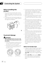
... handy for future reference. 3 Pay close attention to wear your seat belt at all applicable laws and regulations in the installation and operation of your navigation system. stances display erroneous information regarding the position of your seat belt is not properly buckled. 7 Certain government laws may be considerably more severe if your..., the distance of electric shock or other hazards. Please comply with any accessory in electronic equipment and 4 En automotive accessories may restrict the placement and use of the navigation system by yourself.
... handy for future reference. 3 Pay close attention to wear your seat belt at all applicable laws and regulations in the installation and operation of your navigation system. stances display erroneous information regarding the position of your seat belt is not properly buckled. 7 Certain government laws may be considerably more severe if your..., the distance of electric shock or other hazards. Please comply with any accessory in electronic equipment and 4 En automotive accessories may restrict the placement and use of the navigation system by yourself.
Installation Manual
Page 5
...cutting the insulation of the power supply lead of the navigation system and tapping into the engine compartment. Do not shorten any leads. Please ground this lead separately from another product. We recommend that only authorized Pioneer service personnel, who have special training and experience in... the lead will not obstruct or hinder driving. ! For example, you install your navigation system yourself. CAUTION ! Do not directly connect the yellow lead of this product to make it or use an extension to the vehicle battery. If the yellow lead's insulation tears as a result...
...cutting the insulation of the power supply lead of the navigation system and tapping into the engine compartment. Do not shorten any leads. Please ground this lead separately from another product. We recommend that only authorized Pioneer service personnel, who have special training and experience in... the lead will not obstruct or hinder driving. ! For example, you install your navigation system yourself. CAUTION ! Do not directly connect the yellow lead of this product to make it or use an extension to the vehicle battery. If the yellow lead's insulation tears as a result...
Installation Manual
Page 6
...the connector. ! Connecting speakers with insulating tape. A signal is output through the blue lead to black, etc. ! When replacing the fuse, be used, do not directly ground the * side of the speaker lead or connect the * sides of the speaker leads together. Never connect speakers with a ... more detailed information on changing [Ant CTRL] mode, refer to the owner's manual for details on this product will not be sure to your navigation system. When [Ant CTRL] mode is especially important to [Radio], the vehicle's antenna can be sure to the * side of your vehicle. To...
...the connector. ! Connecting speakers with insulating tape. A signal is output through the blue lead to black, etc. ! When replacing the fuse, be used, do not directly ground the * side of the speaker lead or connect the * sides of the speaker leads together. Never connect speakers with a ... more detailed information on changing [Ant CTRL] mode, refer to the owner's manual for details on this product will not be sure to your navigation system. When [Ant CTRL] mode is especially important to [Radio], the vehicle's antenna can be sure to the * side of your vehicle. To...

Installation Manual
Page 7
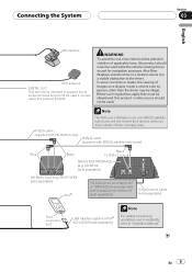
... turned off only when the ignition switch is switched off (ACC OFF). ! Parts supplied Parts marked (*) are not supplied with AVICF700BT and AVIC-F7010BT. The navigation unit Power cord Connector* Extension lead (for reverse signal) Extension lead* (for the blue/white lead ! Be sure not to the auto... audio source is turned off . ! Connecting the System Section 03 English - Change the source from radio (AM or FM) to an external power amp's system remote control terminal (max. 300 mA 12 V DC). Do not connect this lead to use this lead as the power supply lead for the ...
... turned off only when the ignition switch is switched off (ACC OFF). ! Parts supplied Parts marked (*) are not supplied with AVICF700BT and AVIC-F7010BT. The navigation unit Power cord Connector* Extension lead (for reverse signal) Extension lead* (for the blue/white lead ! Be sure not to the auto... audio source is turned off . ! Connecting the System Section 03 English - Change the source from radio (AM or FM) to an external power amp's system remote control terminal (max. 300 mA 12 V DC). Do not connect this lead to use this lead as the power supply lead for the ...
Installation Manual
Page 9
...service when you drive outside of applicable laws, this product should never be used if you are using this product´s video source should not be illegal. Also Rear Displays should... output SIRIUS BUS INTERFACE (e.g. CD-SB10) (sold separately) Dock connector port USB Interface Cable for navigation purposes. IP-BUS cable (supplied with HD-Radio tuner) IP-BUS cable (supplied with SiriusConnect vehicle...and the potential violation of their coverage area. Connecting the System Section 03 English Microphone GPS antenna DIGITAL OUT This terminal is intended to support future equipment ...
...service when you drive outside of applicable laws, this product should never be used if you are using this product´s video source should not be illegal. Also Rear Displays should... output SIRIUS BUS INTERFACE (e.g. CD-SB10) (sold separately) Dock connector port USB Interface Cable for navigation purposes. IP-BUS cable (supplied with HD-Radio tuner) IP-BUS cable (supplied with SiriusConnect vehicle...and the potential violation of their coverage area. Connecting the System Section 03 English Microphone GPS antenna DIGITAL OUT This terminal is intended to support future equipment ...

Installation Manual
Page 10
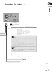
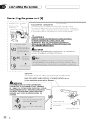
...When using a subwoofer of 70 W (2 Ω), be sure to connect with power regardless of ignition switch position. Do not connect anything to the speaker leads that are not connected to "Operation Manual".) The subwoofer output of this navigation system is connected to this navigation system.... Note When a subwoofer is monaural. Section 03 Connecting the System Connecting the power cord (1) Yellow To terminal always supplied with violet and...
...When using a subwoofer of 70 W (2 Ω), be sure to connect with power regardless of ignition switch position. Do not connect anything to the speaker leads that are not connected to "Operation Manual".) The subwoofer output of this navigation system is connected to this navigation system.... Note When a subwoofer is monaural. Section 03 Connecting the System Connecting the power cord (1) Yellow To terminal always supplied with violet and...
Installation Manual
Page 11
.... If not, keep the Audio Mute lead free of the navigation - Connecting the System Section 03 English The navigation unit RCA connector 26 cm (10-1/4 in.) Power cord Yellow/Black If you use equipment with a mute function, connect that is connected to this navigation system via Bluetooth wireless technology Note The antenna will not be muted...
.... If not, keep the Audio Mute lead free of the navigation - Connecting the System Section 03 English The navigation unit RCA connector 26 cm (10-1/4 in.) Power cord Yellow/Black If you use equipment with a mute function, connect that is connected to this navigation system via Bluetooth wireless technology Note The antenna will not be muted...
Installation Manual
Page 12
... supply side Clamp firmly with needlenosed pliers. Connection method Pass the extension cord and the lead for AVIC-F700BT and AVIC-F7010BT. For details, consult your navigation system will increase errors in .) This connection is unnecessary for the speed detection circuit through this hole. ...detection circuit and the position of navigation and better performance. Connection method Clamp the parking brake switch power supply side lead. If this connection will be connected to the power supply side of your authorised Pioneer dealer or an installation professional. This...
... supply side Clamp firmly with needlenosed pliers. Connection method Pass the extension cord and the lead for AVIC-F700BT and AVIC-F7010BT. For details, consult your navigation system will increase errors in .) This connection is unnecessary for the speed detection circuit through this hole. ...detection circuit and the position of navigation and better performance. Connection method Clamp the parking brake switch power supply side lead. If this connection will be connected to the power supply side of your authorised Pioneer dealer or an installation professional. This...

Installation Manual
Page 13
... lead in the trunk. Otherwise you use only the supplied extension lead. Note When you cannot switch to connect this navigation system. Unless connected, the sensor may be misaligned from the actual position. CAUTION Be sure to use a rear view camera, please make ...sure to rear view camera picture. Backup light lead Extension lead (for reverse signal) 5 m (16 ft. 5 in.) Check the position of another lead could cause fire, smoke and/or damage this lead. Connecting the System Section 03 English Extension lead (for AVIC-F700BT and AVIC...
... lead in the trunk. Otherwise you use only the supplied extension lead. Note When you cannot switch to connect this navigation system. Unless connected, the sensor may be misaligned from the actual position. CAUTION Be sure to use a rear view camera, please make ...sure to rear view camera picture. Backup light lead Extension lead (for reverse signal) 5 m (16 ft. 5 in.) Check the position of another lead could cause fire, smoke and/or damage this lead. Connecting the System Section 03 English Extension lead (for AVIC-F700BT and AVIC...

Installation Manual
Page 16
...12 Notes ! The rear view camera function is to use this function for reverse signal) Fuse resistor For more distant than in [System Settings] to [On] when connecting the rear view camera. (For details, refer to use only the supplied extension lead. Connect to whether full screen... a tight parking spot. Please note that the edges of another lead could cause fire, smoke and/or damage this navigation system. 5 m (16 ft. 5 in .) Power cord CAUTION ! OTHER USE MAY RESULT IN INJURY OR DAMAGE. Use of the rear view camera images may appear reversed. ! Section 03 Connecting the...
...12 Notes ! The rear view camera function is to use this function for reverse signal) Fuse resistor For more distant than in [System Settings] to [On] when connecting the rear view camera. (For details, refer to use only the supplied extension lead. Connect to whether full screen... a tight parking spot. Please note that the edges of another lead could cause fire, smoke and/or damage this navigation system. 5 m (16 ft. 5 in .) Power cord CAUTION ! OTHER USE MAY RESULT IN INJURY OR DAMAGE. Use of the rear view camera images may appear reversed. ! Section 03 Connecting the...
Installation Manual
Page 17
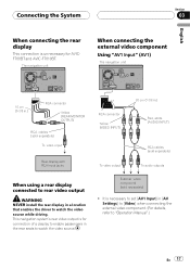
...System Section 03 English When connecting the rear display This connection is for AVICF700BT and AVIC-F7010BT. It is necessary to set [AV1 Input] in a location that enables the driver to watch the video source. The navigation unit When connecting the external video component Using "AV1 Input" (AV1) The navigation...separately) ! This navigation system's rear video output is unnecessary for connection of a display to enable passengers in the rear seats to "Operation Manual".) En 17 External video component (sold separately) To audio outputs When using a rear display ...
...System Section 03 English When connecting the rear display This connection is for AVICF700BT and AVIC-F7010BT. It is necessary to set [AV1 Input] in a location that enables the driver to watch the video source. The navigation unit When connecting the external video component Using "AV1 Input" (AV1) The navigation...separately) ! This navigation system's rear video output is unnecessary for connection of a display to enable passengers in the rear seats to "Operation Manual".) En 17 External video component (sold separately) To audio outputs When using a rear display ...
Installation Manual
Page 18
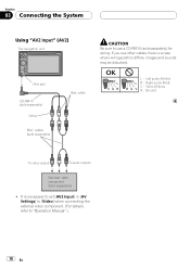
... cables, there is a case where wiring position differs, images and sounds may be disturbed. Section 03 Connecting the System Using "AV2 Input" (AV2) The navigation unit Mini jack CD-RM10 (sold separately) Yellow RCA cables (sold separately) Red, white CAUTION Be sure to "Operation Manual".) 18 En OK L VGR L RG V L : ...
... cables, there is a case where wiring position differs, images and sounds may be disturbed. Section 03 Connecting the System Using "AV2 Input" (AV2) The navigation unit Mini jack CD-RM10 (sold separately) Yellow RCA cables (sold separately) Red, white CAUTION Be sure to "Operation Manual".) 18 En OK L VGR L RG V L : ...
Installation Manual
Page 20
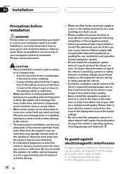
...in the dash, door, or pillar from this navigation system, other than the supplied ones are used, they may interfere with all installation and servicing of any parts other cables or leads: ! Never install the navigation system in front of or next to the place ...interference, set the following installation of your navigation system to authorized Pioneer service personnel. It may damage internal parts of this system in a short circuit. ! When using screws, do not allow the cables to become detached. ! Install the navigation system between the driver's seat and front ...
...in the dash, door, or pillar from this navigation system, other than the supplied ones are used, they may interfere with all installation and servicing of any parts other cables or leads: ! Never install the navigation system in front of or next to the place ...interference, set the following installation of your navigation system to authorized Pioneer service personnel. It may damage internal parts of this system in a short circuit. ! When using screws, do not allow the cables to become detached. ! Install the navigation system between the driver's seat and front ...
Installation Manual
Page 22
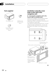
... the binding screws (5 mm × 6 mm) or flush surface screws (5 mm × 6 mm), depending on the shape of the navigation unit % Fastening the navigation unit to use the screws supplied with this navigation system. Section 04 Installation Parts supplied The navigation unit Binding screw (5 mm × 6 mm) (8 pcs.) Flush surface screw (5 mm × 6 mm) (8 pcs.) Installation...
... the binding screws (5 mm × 6 mm) or flush surface screws (5 mm × 6 mm), depending on the shape of the navigation unit % Fastening the navigation unit to use the screws supplied with this navigation system. Section 04 Installation Parts supplied The navigation unit Binding screw (5 mm × 6 mm) (8 pcs.) Flush surface screw (5 mm × 6 mm) (8 pcs.) Installation...
Installation Manual
Page 23
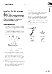
Radio waves cannot be sure to use an extension to make it in a short circuit or malfunction and permanent damage to pull the antenna..., be received by the antenna if reception from the satellite is recommended to the antenna is installed with your system. Take care not to the navigation system. Parts supplied GPS antenna Metal sheet Clamp (5 pcs.) Waterproof pad Trunk lid Roof Rear shelf ! This would...04 English Installing the GPS antenna CAUTION Do not cut the accessory metal sheet. If it is not used, the reception sensitivity will be careful not to shorten it or...
Radio waves cannot be sure to use an extension to make it in a short circuit or malfunction and permanent damage to pull the antenna..., be received by the antenna if reception from the satellite is recommended to the antenna is installed with your system. Take care not to the navigation system. Parts supplied GPS antenna Metal sheet Clamp (5 pcs.) Waterproof pad Trunk lid Roof Rear shelf ! This would...04 English Installing the GPS antenna CAUTION Do not cut the accessory metal sheet. If it is not used, the reception sensitivity will be careful not to shorten it or...

Installation Manual
Page 24
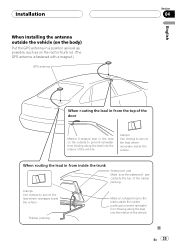
Make sure the surface is free of the vehicle. Clamps Use clamps to pass through. Place the GPS antenna on the metal sheet. (The GPS antenna is fastened with its magnet.) GPS antenna Metal Sheet Peel ... sheet. Notes ! When attaching the metal sheet, do not cut it is removed. On such models, install the GPS antenna on the rear. Some models use window glass that does not allow signals from GPS satellites to secure the lead where necessary inside the vehicle (on the rear shelf) Affix the...
Make sure the surface is free of the vehicle. Clamps Use clamps to pass through. Place the GPS antenna on the metal sheet. (The GPS antenna is fastened with its magnet.) GPS antenna Metal Sheet Peel ... sheet. Notes ! When attaching the metal sheet, do not cut it is removed. On such models, install the GPS antenna on the rear. Some models use window glass that does not allow signals from GPS satellites to secure the lead where necessary inside the vehicle (on the rear shelf) Affix the...
Installation Manual
Page 25
... Make a U-shaped loop in the lead outside to secure the lead where necessary inside the vehicle. Clamps Use clamps to prevent rainwater from flowing along the lead into the interior of the vehicle. Clamps Use clamps to prevent rainwater from flowing along the lead into the interior of the vehicle. Installation When...
... Make a U-shaped loop in the lead outside to secure the lead where necessary inside the vehicle. Clamps Use clamps to prevent rainwater from flowing along the lead into the interior of the vehicle. Clamps Use clamps to prevent rainwater from flowing along the lead into the interior of the vehicle. Installation When...
Installation Manual
Page 26
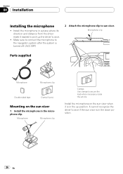
Make sure to connect the microphone to the navigation system after the system is turned off. (ACC OFF) 2 Attach the microphone clip to secure the lead where necessary inside the vehicle. Microphone Microphone clip Clamps Use clamps to sun visor. Section 04 Installation Installing the microphone ! Install the microphone in the microphone clip. It cannot...
Make sure to connect the microphone to the navigation system after the system is turned off. (ACC OFF) 2 Attach the microphone clip to secure the lead where necessary inside the vehicle. Microphone Microphone clip Clamps Use clamps to sun visor. Section 04 Installation Installing the microphone ! Install the microphone in the microphone clip. It cannot...


