Owner's Manual
Page 62
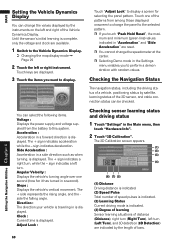
... driving status of a vehicle, positioning status by the length of the 3D sensor, and cable connection status can select the following items. Voltage : Displays the power supply and voltage supplied from among those displayed onscreen to change the speedometer at the center. ❒ Selecting Demo mode in the Main menu, then...
... driving status of a vehicle, positioning status by the length of the 3D sensor, and cable connection status can select the following items. Voltage : Displays the power supply and voltage supplied from among those displayed onscreen to change the speedometer at the center. ❒ Selecting Demo mode in the Main menu, then...
Owner's Manual
Page 63
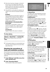
... rotational speed when your vehicle is indicated. If the voltage does not fall within the range of 11 to 15V, check that power cable connection is correct. (6) Illumination When the headlights or small lamps of a vehicle are properly connected between the navigation unit and...not use its sensor memory based on the outer dimensions of the tires. When the parking brake is released, "Off" is displayed. (5) Power Voltage The power supply (reference value) provided from how many satellites the signal is received. If reception is poor, "NOK" appears. (3) Installation Position The...
... rotational speed when your vehicle is indicated. If the voltage does not fall within the range of 11 to 15V, check that power cable connection is correct. (6) Illumination When the headlights or small lamps of a vehicle are properly connected between the navigation unit and...not use its sensor memory based on the outer dimensions of the tires. When the parking brake is released, "Off" is displayed. (5) Power Voltage The power supply (reference value) provided from how many satellites the signal is received. If reception is poor, "NOK" appears. (3) Installation Position The...
Owner's Manual
Page 100
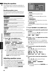
...You can select the details of the equalizer band. HIGH 3 Touch "+" or "-" to check the effect of the equalizer curves: Equalizer curve POWERFUL POWERFUL is a curve in which low-pitched and high-pitched sounds are slightly boosted. Touch "EQ" button repeatedly to switch between FLAT and a ... vocal range, is increased or decreased. 4 Touch or to select the desired fre- FLAT FLAT is a flat curve in the following equalizers: POWERFUL - VOCAL - Touch or until the desired frequency appears in which the midrange, which nothing is updated. 98 quency. LOW: 40 - 80 ...
...You can select the details of the equalizer band. HIGH 3 Touch "+" or "-" to check the effect of the equalizer curves: Equalizer curve POWERFUL POWERFUL is a curve in which low-pitched and high-pitched sounds are slightly boosted. Touch "EQ" button repeatedly to switch between FLAT and a ... vocal range, is increased or decreased. 4 Touch or to select the desired fre- FLAT FLAT is a flat curve in the following equalizers: POWERFUL - VOCAL - Touch or until the desired frequency appears in which the midrange, which nothing is updated. 98 quency. LOW: 40 - 80 ...
Owner's Manual
Page 117
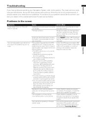
... clear. If necessary, consult the dealer that the cables are properly connected. Connect the speed signal input (pink lead wire) of the power cable correctly, and reset the 3D Hybrid Sensor memory ("Learning Status"). 115 While this may block the reception of GPS signals. The unit... common problems. If a solution to install the correct fuse with the same rate. You cannot position your dealer or the nearest authorized Pioneer service facility. Cause Leads and connectors are correct. Action (See) Confirm once more that the navigation unit is in your problem cannot be...
... clear. If necessary, consult the dealer that the cables are properly connected. Connect the speed signal input (pink lead wire) of the power cable correctly, and reset the 3D Hybrid Sensor memory ("Learning Status"). 115 While this may block the reception of GPS signals. The unit... common problems. If a solution to install the correct fuse with the same rate. You cannot position your dealer or the nearest authorized Pioneer service facility. Cause Leads and connectors are correct. Action (See) Confirm once more that the navigation unit is in your problem cannot be...
Owner's Manual
Page 118
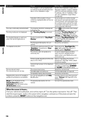
... is always set to adjust the picture quality. The traveling direction is installed with VOL (+,-) button. The attenuator or mute is misaligned after a U-turn the power to the navigation unit back on the screen and change the map display. Read about the "Day/Night Display" setting (➞ Page 65) and, if...
... is always set to adjust the picture quality. The traveling direction is installed with VOL (+,-) button. The attenuator or mute is misaligned after a U-turn the power to the navigation unit back on the screen and change the map display. Read about the "Day/Night Display" setting (➞ Page 65) and, if...
Owner's Manual
Page 120
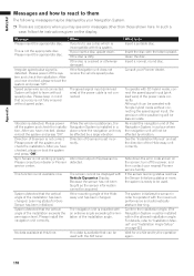
...with the XM tuner. Speed pulse wire is not available now. Please power off the system and check the installation. No data available at this system. The screen cannot be affected by your Pioneer dealer. Clean the disc. To operate with Simple hybrid mode without ... has been initialized. Vibration is not fully ensured without speed pulse. Please install the navigation unit correctly. Please power off the power, and then contact your dealer or Pioneer service center. Insert a normal, round disc. After you insert a disc upside down the error code shown on...
...with the XM tuner. Speed pulse wire is not available now. Please power off the system and check the installation. No data available at this system. The screen cannot be affected by your Pioneer dealer. Clean the disc. To operate with Simple hybrid mode without ... has been initialized. Vibration is not fully ensured without speed pulse. Please install the navigation unit correctly. Please power off the power, and then contact your dealer or Pioneer service center. Insert a normal, round disc. After you insert a disc upside down the error code shown on...
Owner's Manual
Page 122
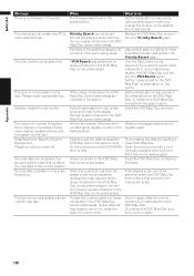
... an attempt was performed on areas not stored on the DVD Map Disc (unrecorded areas). Scaling up lens of the selected category do not turn power off. Or, the pick-up . Delete unnecessary data and try to areas not stored on the DVD Map Disc (unrecorded areas). Facilities of the DVD...
... an attempt was performed on areas not stored on the DVD Map Disc (unrecorded areas). Scaling up lens of the selected category do not turn power off. Or, the pick-up . Delete unnecessary data and try to areas not stored on the DVD Map Disc (unrecorded areas). Facilities of the DVD...
Installation Manual
Page 6
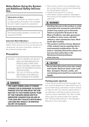
CAUTION: THE USE OF OPTICAL INSTRUMENTS WITH THIS PRODUCT WILL INCREASE EYE HAZARD. • THE LIGHT GREEN LEAD AT POWER CONNECTOR IS DESIGNED TO DETECT PARKED STATUS AND MUST BE CONNECTED TO THE POWER SUPPLY SIDE OF THE PARKING BRAKE SWITCH. Parking brake interlock Certain functions offered by this material may be sure...
CAUTION: THE USE OF OPTICAL INSTRUMENTS WITH THIS PRODUCT WILL INCREASE EYE HAZARD. • THE LIGHT GREEN LEAD AT POWER CONNECTOR IS DESIGNED TO DETECT PARKED STATUS AND MUST BE CONNECTED TO THE POWER SUPPLY SIDE OF THE PARKING BRAKE SWITCH. Parking brake interlock Certain functions offered by this material may be sure...
Installation Manual
Page 15
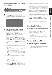
Chapter 1 How to Use Navigation Unit and Names of basic functions by this unit. The Navigation System's power supply comes on . "SIRIUS" (SIRIUS tuner) -"RADIO" (tuner) - "S-DVD" (DVD player/ multi-DVD player) - "CD" [CD, MP3/WMA/ WAV](built-in the CD loading slot. - ... the ACC (ignition) OFF. 13 When no disc is set to off . ➲ "AUTO ANTENNA" ➞ Operation Manual Adjusting the Volume 2 Press SRC button to a Pioneer product (such as a source, enables control of the Parts Turning the Unit On and Selecting a Source • If the program is set in CD drive...
Chapter 1 How to Use Navigation Unit and Names of basic functions by this unit. The Navigation System's power supply comes on . "SIRIUS" (SIRIUS tuner) -"RADIO" (tuner) - "S-DVD" (DVD player/ multi-DVD player) - "CD" [CD, MP3/WMA/ WAV](built-in the CD loading slot. - ... the ACC (ignition) OFF. 13 When no disc is set to off . ➲ "AUTO ANTENNA" ➞ Operation Manual Adjusting the Volume 2 Press SRC button to a Pioneer product (such as a source, enables control of the Parts Turning the Unit On and Selecting a Source • If the program is set in CD drive...

Installation Manual
Page 19
... the disc and insert the disc to turn on the back light. The fuse is not applied. The navigation does not boot up or down . Power doesn't turn on . The parking brake is blown.
... the disc and insert the disc to turn on the back light. The fuse is not applied. The navigation does not boot up or down . Power doesn't turn on . The parking brake is blown.
Installation Manual
Page 23
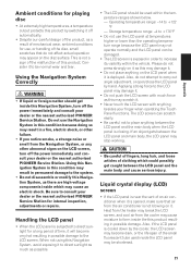
...When not using this Navigation System, avoid exposing it to be used inside this Navigation System, turn off the power immediately and consult your dealer or the nearest authorized PIONEER Service Station. Please do not affect actual operation may appear on the disc surface. Using the Navigation System ... noise or smell from the Navigation System, or any other abnormal signs on the LCD screen, turn off the power immediately and consult your dealer or the nearest authorized PIONEER Service Station. Liquid crystal display (LCD) screen • If the LCD panel is near the vent of an...
...When not using this Navigation System, avoid exposing it to be used inside this Navigation System, turn off the power immediately and consult your dealer or the nearest authorized PIONEER Service Station. Please do not affect actual operation may appear on the disc surface. Using the Navigation System ... noise or smell from the Navigation System, or any other abnormal signs on the LCD screen, turn off the power immediately and consult your dealer or the nearest authorized PIONEER Service Station. Liquid crystal display (LCD) screen • If the LCD panel is near the vent of an...
Installation Manual
Page 24
...etc. Appendix • Small black dots or white dots (bright dots) may be projected. The fluorescent tube should last for a while after the power is turned on. • The LCD screen will no longer be dark for approximately 10,000 hours, depending on the LCD screen. When the ...display to prevent disruption of the video by the appearance of the fluorescent tube.) - If this happens, consult your dealer or the nearest authorized PIONEER Service Station. 22 These are due to scratch the surface. Do not use harsh or abrasive chemical cleaners. Glossary ➲ Glossary ➞ Appendix...
...etc. Appendix • Small black dots or white dots (bright dots) may be projected. The fluorescent tube should last for a while after the power is turned on. • The LCD screen will no longer be dark for approximately 10,000 hours, depending on the LCD screen. When the ...display to prevent disruption of the video by the appearance of the fluorescent tube.) - If this happens, consult your dealer or the nearest authorized PIONEER Service Station. 22 These are due to scratch the surface. Do not use harsh or abrasive chemical cleaners. Glossary ➲ Glossary ➞ Appendix...
Installation Manual
Page 25
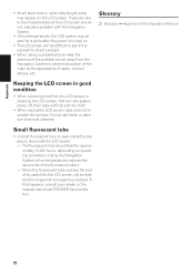
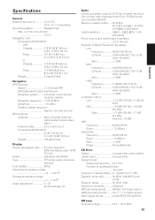
...SPS (Standard Positioning Service) Reception system ........ 8-channel multi-channel reception system Reception frequency ... 1,575.42 MHz Sensitivity 130 dBm Position update frequency Approx. Maximum power output ......50 W ✕ 4 50 W ✕ 2 ch/4 Ω + 70 W ✕ 1 ch/2 Ω (for subwoofer) ...9 (2ch audio) Wave signal format Linear-PCM, MS ADPCM FM tuner Frequency range 87.9 - 107.9 MHz 23 Appendix Specifications General Rated power source 14.4 V DC (10.8 - 15.1 V allowable) Grounding system Negative type Max. current consumption 10.0 A Navigation unit: Dimensions ...
...SPS (Standard Positioning Service) Reception system ........ 8-channel multi-channel reception system Reception frequency ... 1,575.42 MHz Sensitivity 130 dBm Position update frequency Approx. Maximum power output ......50 W ✕ 4 50 W ✕ 2 ch/4 Ω + 70 W ✕ 1 ch/2 Ω (for subwoofer) ...9 (2ch audio) Wave signal format Linear-PCM, MS ADPCM FM tuner Frequency range 87.9 - 107.9 MHz 23 Appendix Specifications General Rated power source 14.4 V DC (10.8 - 15.1 V allowable) Grounding system Negative type Max. current consumption 10.0 A Navigation unit: Dimensions ...

Other Manual
Page 3
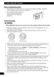
...Italiano Nederlands 2 Parts supplied - cle (on the rear shelf) - Parts supplied Connecting the system 7 Connecting the power cord (1 9 Connecting the power cord (2 11 When connecting to rear video output Installation 17 To guard against electromagnetic interference 18 Before installing 18 ...cle (on the body) After Installing this product - Installation notes - Parts supplied - When using a display connected to separately sold power amp 13 When connecting a Rear view camera 15 When connecting the external video component and the display 16 - English Contents IMPORTANT ...
...Italiano Nederlands 2 Parts supplied - cle (on the rear shelf) - Parts supplied Connecting the system 7 Connecting the power cord (1 9 Connecting the power cord (2 11 When connecting to rear video output Installation 17 To guard against electromagnetic interference 18 Before installing 18 ...cle (on the body) After Installing this product - Installation notes - Parts supplied - When using a display connected to separately sold power amp 13 When connecting a Rear view camera 15 When connecting the external video component and the display 16 - English Contents IMPORTANT ...
Other Manual
Page 5
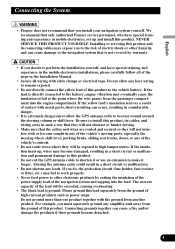
...product. We recommend that you decide to the vehicle battery. NEVER SERVICE THIS PRODUCT YOURSELF. If the yellow lead's insulation tears as power amps. The current capacity of the lead will be exceeded, causing overheating. • The black lead is not covered by cutting...steering column or shift lever. Please ground this product. English Español Deutsch Connecting the System • Pioneer does not recommend that only authorized Pioneer service personnel, who have special training and experience in the mobile electronics installations, please carefully follow all of the...
...product. We recommend that you decide to the vehicle battery. NEVER SERVICE THIS PRODUCT YOURSELF. If the yellow lead's insulation tears as power amps. The current capacity of the lead will be exceeded, causing overheating. • The black lead is not covered by cutting...steering column or shift lever. Please ground this product. English Español Deutsch Connecting the System • Pioneer does not recommend that only authorized Pioneer service personnel, who have special training and experience in the mobile electronics installations, please carefully follow all of the...
Other Manual
Page 6
... of the speaker lead or connect the ≠ sides of the speaker lead on this product. • If the RCA pin jack on connecting the power amp and other units, then make connections accordingly. • Since a unique BPTL circuit is employed, do not remove the caps attached to the end of...
... of the speaker lead or connect the ≠ sides of the speaker lead on this product. • If the RCA pin jack on connecting the power amp and other units, then make connections accordingly. • Since a unique BPTL circuit is employed, do not remove the caps attached to the end of...
Other Manual
Page 7
...auto antenna. Connecting speakers with this system, be sure not to connect the blue lead to the power terminal of the vehicle. Likewise, do not connect the blue lead to the amp's power terminal. The control signal is being used with output and/or impedance values other than 50 W ...channel or impedance outside of the 4 ohms to 8 ohms specifications to an external power amp's system remote control terminal (max. 300 mA 12 V DC). English • Never connect speakers with an output rating of less than those ...
...auto antenna. Connecting speakers with this system, be sure not to connect the blue lead to the power terminal of the vehicle. Likewise, do not connect the blue lead to the amp's power terminal. The control signal is being used with output and/or impedance values other than 50 W ...channel or impedance outside of the 4 ohms to 8 ohms specifications to an external power amp's system remote control terminal (max. 300 mA 12 V DC). English • Never connect speakers with an output rating of less than those ...
Other Manual
Page 8
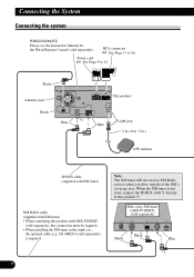
... (e.g. When the XM tuner is required. 7 Note: The XM tuner will not receive XM Radio service when you drive outside of the XM's coverage area. Power cord See Page 9 to this product with GEX-P10XMT (sold separately) Black Black Blue *1 Hide-away XM tuner (GEX-P10XMT) (sold separately), this connection must...
... (e.g. When the XM tuner is required. 7 Note: The XM tuner will not receive XM Radio service when you drive outside of the XM's coverage area. Power cord See Page 9 to this product with GEX-P10XMT (sold separately) Black Black Blue *1 Hide-away XM tuner (GEX-P10XMT) (sold separately), this connection must...
Other Manual
Page 10
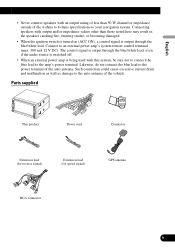
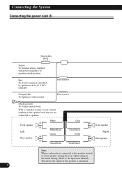
... of ignition switch position. Orange/white To lighting switch terminal. Fuse resistor Fuse resistor Black (ground) To vehicle (metal) body. Connecting the System Connecting the power cord (1) Fuse holder Yellow To terminal always supplied with...
... of ignition switch position. Orange/white To lighting switch terminal. Fuse resistor Fuse resistor Black (ground) To vehicle (metal) body. Connecting the System Connecting the power cord (1) Fuse holder Yellow To terminal always supplied with...
Other Manual
Page 11
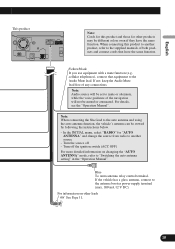
... To Auto-antenna relay control terminal. In the INITIAL menu, select "RADIO" for "AUTO ANTENNA" and change the source from radio to the antenna booster power supply terminal (max. 300 mA 12 V DC). When connecting this product and those for other leads See Page 11. English Español Deutsch This...
... To Auto-antenna relay control terminal. In the INITIAL menu, select "RADIO" for "AUTO ANTENNA" and change the source from radio to the antenna booster power supply terminal (max. 300 mA 12 V DC). When connecting this product and those for other leads See Page 11. English Español Deutsch This...


