Owner's Manual
Page 85
...When the ignition switch is turned ON (or turned to your display. Additional Information Appendix Additional Information Troubleshooting Common Symptom Cause Action (See) Power doesn't turn on . Confirm once more . The fuse is incorrect. Rectify the reason for your video is loaded. Be very sure... Check what type the disc is low. cannot play. No sounds are the same. The volume level will not rise. Connect the cables correctly. The unit is no sound. There is performing still, slow mo- Connect a parking brake cord, and apply the nected. parking...
...When the ignition switch is turned ON (or turned to your display. Additional Information Appendix Additional Information Troubleshooting Common Symptom Cause Action (See) Power doesn't turn on . Confirm once more . The fuse is incorrect. Rectify the reason for your video is loaded. Be very sure... Check what type the disc is low. cannot play. No sounds are the same. The volume level will not rise. Connect the cables correctly. The unit is no sound. There is performing still, slow mo- Connect a parking brake cord, and apply the nected. parking...

Owner's Manual
Page 89
...noise level is not connected. Error. Additional Information Appendix iPod is not charged but operates correctly Check if the connection cable for iPod player/USB memory consumes shorted out (e.g., not caught in metal objects). Please check front SP., Error. Additional Information Understanding ...checking, turn the ignition switch able current). Please check subwoofer The microphone cannot pick up the measuring tone of the power amp connected to see what the problem is and the suggested method of car interior acoustic characteristics is not possible using...
...noise level is not connected. Error. Additional Information Appendix iPod is not charged but operates correctly Check if the connection cable for iPod player/USB memory consumes shorted out (e.g., not caught in metal objects). Please check front SP., Error. Additional Information Understanding ...checking, turn the ignition switch able current). Please check subwoofer The microphone cannot pick up the measuring tone of the power amp connected to see what the problem is and the suggested method of car interior acoustic characteristics is not possible using...
Installation Manual
Page 2
...DETECT PARKED STATUS AND MUST BE CONNECTED TO THE POWER SUPPLY SIDE OF THE PARKING BRAKE SWITCH. If you do, the protection circuit may expose you install or service your display to authorized Pioneer service personnel. • Secure all wiring with cable clamps or electrical tape. Where such regulations apply... Make sure that you to risk of electric shock or other than the driver may eventually cause the insulation to fail at this unit's DVD features should not be used while the vehicle is extremely dangerous to allow any leads. Take extra care in a location where it will ...
...DETECT PARKED STATUS AND MUST BE CONNECTED TO THE POWER SUPPLY SIDE OF THE PARKING BRAKE SWITCH. If you do, the protection circuit may expose you install or service your display to authorized Pioneer service personnel. • Secure all wiring with cable clamps or electrical tape. Where such regulations apply... Make sure that you to risk of electric shock or other than the driver may eventually cause the insulation to fail at this unit's DVD features should not be used while the vehicle is extremely dangerous to allow any leads. Take extra care in a location where it will ...
Installation Manual
Page 3
...prescribed. - Do not pass the yellow cable through blue/white cable when this unit is powered on the ignition switch. Never cut the insulation of the power cable of the auto antenna. Never wire the speaker negative cable directly to the power terminal of this unit in other than ...lie against metal parts. - Current capacity of the same color. • Black cable is limited. - Connect it to the antenna booster power supply terminal. • Never connect blue/white cable to an external power amp's system remote control or the vehicle's auto-antenna relay control terminal (max....
...prescribed. - Do not pass the yellow cable through blue/white cable when this unit is powered on the ignition switch. Never cut the insulation of the power cable of the auto antenna. Never wire the speaker negative cable directly to the power terminal of this unit in other than ...lie against metal parts. - Current capacity of the same color. • Black cable is limited. - Connect it to the antenna booster power supply terminal. • Never connect blue/white cable to an external power amp's system remote control or the vehicle's auto-antenna relay control terminal (max....
Installation Manual
Page 4
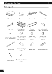
Connecting the Units Parts supplied This product Tuner box Power cord Antenna cable USB cable Mounting sleeve (pre-installed) Trim ring (pre-installed) Side bracket (small) (2 pcs.) (pre-installed) Screw (2 mm × 3 mm) (4 pcs.) (pre-installed) Flush surface screw (5 mm × 6 mm) (6 pcs.) (2 are pre-installed.) Binding screw (5 mm × 6 mm) (4 pcs.) Binding screw (4 mm × 3 mm) (4 pcs.) Concealing tape Side bracket (large) (2 pcs.) Rubber bush Double-ended screw Touch panel pen Screw (2 mm × 7 mm) (2 pcs.) 3
Connecting the Units Parts supplied This product Tuner box Power cord Antenna cable USB cable Mounting sleeve (pre-installed) Trim ring (pre-installed) Side bracket (small) (2 pcs.) (pre-installed) Screw (2 mm × 3 mm) (4 pcs.) (pre-installed) Flush surface screw (5 mm × 6 mm) (6 pcs.) (2 are pre-installed.) Binding screw (5 mm × 6 mm) (4 pcs.) Binding screw (4 mm × 3 mm) (4 pcs.) Concealing tape Side bracket (large) (2 pcs.) Rubber bush Double-ended screw Touch panel pen Screw (2 mm × 7 mm) (2 pcs.) 3
Installation Manual
Page 6
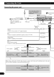
... ≠ Subwoofer (4 Ω) When using a subwoofer of this unit. Red Connect to connect with auxiliary equipment. Green Not used. Use a mini plug cable to lighting switch terminal. Orange/white Connect to connect with Violet and Violet/black leads of 70 W (2 Ω), be sure to terminal controlled by ignition... switch (12 V DC). Connecting the Units Connecting the power cord 1.5 m (4 ft. 11 in .) USB input This product Fuse (10 A) Gray Yellow Connect to Green and Green/black leads.
... ≠ Subwoofer (4 Ω) When using a subwoofer of this unit. Red Connect to connect with auxiliary equipment. Green Not used. Use a mini plug cable to lighting switch terminal. Orange/white Connect to connect with Violet and Violet/black leads of 70 W (2 Ω), be sure to terminal controlled by ignition... switch (12 V DC). Connecting the Units Connecting the power cord 1.5 m (4 ft. 11 in .) USB input This product Fuse (10 A) Gray Yellow Connect to Green and Green/black leads.
Installation Manual
Page 7
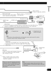
... 80 cm (2 ft. 7 in.) Tuner box (supplied) IP-BUS input IP-BUS cable (Blue) Multi-CD player (sold separately) Yellow/black Antenna cable If you connect the separately sold multichannel processor (e.g., DEQ-P8000) to this lead to the... Audio Mute lead on the vehicle model. English Español Wired remote input Interface cable (e.g., CD-IU205V) Hard-wired remote control adaptor (sold separately) can be connected to the power...
... 80 cm (2 ft. 7 in.) Tuner box (supplied) IP-BUS input IP-BUS cable (Blue) Multi-CD player (sold separately) Yellow/black Antenna cable If you connect the separately sold multichannel processor (e.g., DEQ-P8000) to this lead to the... Audio Mute lead on the vehicle model. English Español Wired remote input Interface cable (e.g., CD-IU205V) Hard-wired remote control adaptor (sold separately) can be connected to the power...
Installation Manual
Page 9
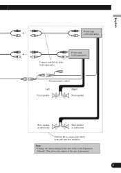
The subwoofer output of this unit is monaural. 8 English Español Deutsch Power amp (sold separately) Connect with RCA cables (sold separately) Power amp (sold separately) System remote control Left Right + + Front speaker Front speaker ≠ ≠ Français Italiano Nederlands PyÒÒÍËÈ Rear speaker + or subwoofer ≠ + Rear speaker ≠ or subwoofer Perform these connections when using the optional amplifier. Note: • Change the initial setting of this unit (refer to the Operation Manual).
The subwoofer output of this unit is monaural. 8 English Español Deutsch Power amp (sold separately) Connect with RCA cables (sold separately) Power amp (sold separately) System remote control Left Right + + Front speaker Front speaker ≠ ≠ Français Italiano Nederlands PyÒÒÍËÈ Rear speaker + or subwoofer ≠ + Rear speaker ≠ or subwoofer Perform these connections when using the optional amplifier. Note: • Change the initial setting of this unit (refer to the Operation Manual).
Installation Manual
Page 12
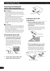
... danger of a fatal accident. • Avoid installing this unit in locations where the operation of the brake may result in a traffic accident. Connect the optical cable to the main unit. Otherwise, it disturbs driving stability, which may be spilled on the back of the unit. If this unit is likely to... connection box with the protection tape and fasten with the lock tie 11 Fasten with the power code using the lock tie. Connecting the optical cable 1. Wrap with the hook and loop fastener or lock tie. Fasten the ground lead to an accident or other problems. • Do not install ...
... danger of a fatal accident. • Avoid installing this unit in locations where the operation of the brake may result in a traffic accident. Connect the optical cable to the main unit. Otherwise, it disturbs driving stability, which may be spilled on the back of the unit. If this unit is likely to... connection box with the protection tape and fasten with the lock tie 11 Fasten with the power code using the lock tie. Connecting the optical cable 1. Wrap with the hook and loop fastener or lock tie. Fasten the ground lead to an accident or other problems. • Do not install ...


