
Owner Manual
Page 1
Please retain this manual will enable you for future reference. Following the instructions in the unit. Please read this manual thoroughly before making connections and plugging in this manual for purchasing an Onkyo AV Receiver. Setup Menu 82 Using the Remote Controller 124 Miscellaneous 143 En Contents AV Receiver Getting Started 2 TX-NR1000 TX-NR5000E Installation and Connections 18 Instruction Manual Operations 48 Thank you to obtain optimum performance and listening enjoyment from your new AV Receiver.
Please retain this manual will enable you for future reference. Following the instructions in the unit. Please read this manual thoroughly before making connections and plugging in this manual for purchasing an Onkyo AV Receiver. Setup Menu 82 Using the Remote Controller 124 Miscellaneous 143 En Contents AV Receiver Getting Started 2 TX-NR1000 TX-NR5000E Installation and Connections 18 Instruction Manual Operations 48 Thank you to obtain optimum performance and listening enjoyment from your new AV Receiver.

Owner Manual
Page 4
... 4 Connection Using HDMI Terminals 43 Connecting Components not Reached by the Remote Controller Signals (IR IN/OUT)..... 45 If Remote Controller Signal Does not Reach the TX-NR1000/TX-NR5000E Remote Sensor .... 45 If Remote Controller Signal Does not Reach Other Components 46 Using an External Device with... 12V Trigger Terminal 46 Connecting -compatible AV Components 47 Connections for Remote Control 47 Operations Basic Operation of Remote Controller Buttons 48 To Operate the TX-NR1000/TX-NR5000E (AMP Mode 48 To Select an Input Source 48 To Operate a Connected ...
... 4 Connection Using HDMI Terminals 43 Connecting Components not Reached by the Remote Controller Signals (IR IN/OUT)..... 45 If Remote Controller Signal Does not Reach the TX-NR1000/TX-NR5000E Remote Sensor .... 45 If Remote Controller Signal Does not Reach Other Components 46 Using an External Device with... 12V Trigger Terminal 46 Connecting -compatible AV Components 47 Connections for Remote Control 47 Operations Basic Operation of Remote Controller Buttons 48 To Operate the TX-NR1000/TX-NR5000E (AMP Mode 48 To Select an Input Source 48 To Operate a Connected ...

Owner Manual
Page 5
... Sub-menu 121 Client Sub-menu 122 Lock/Version Setup 123 Lock Setup Sub-menu 123 Firmware Version Sub-menu 123 Using the Remote Controller Operating Onkyo Products Using the Remote Controller 124 Operating Onkyo Products Using the Connection 124 DVD Mode 124 CD Mode 126 MiniDisc Mode 127 Tape Mode 128 Using the...
... Sub-menu 121 Client Sub-menu 122 Lock/Version Setup 123 Lock Setup Sub-menu 123 Firmware Version Sub-menu 123 Using the Remote Controller Operating Onkyo Products Using the Remote Controller 124 Operating Onkyo Products Using the Connection 124 DVD Mode 124 CD Mode 126 MiniDisc Mode 127 Tape Mode 128 Using the...
Owner Manual
Page 7
...8226; Absolute Ground Plate • Large, Fluorescent, 35 Dot Matrix Display With 4 Mode Dimmer • For Ultimate Control-The Last Remote You'll Ever Need • A-Form Listening Mode Memory In catalogs and on packaging, the letter added to come. "Dolby," ...Onkyo Corporation. • Windows Media and the Windows logo are trandemarks, or registered trademarks of Digital Theater Systems, Inc. • The i.LINK logo is prohibited." patents and other limited consumer uses only unless otherwise authorized by U.S. THX Ultra2 requirements define hundreds of the TX-NR1000/TX...
...8226; Absolute Ground Plate • Large, Fluorescent, 35 Dot Matrix Display With 4 Mode Dimmer • For Ultimate Control-The Last Remote You'll Ever Need • A-Form Listening Mode Memory In catalogs and on packaging, the letter added to come. "Dolby," ...Onkyo Corporation. • Windows Media and the Windows logo are trandemarks, or registered trademarks of Digital Theater Systems, Inc. • The i.LINK logo is prohibited." patents and other limited consumer uses only unless otherwise authorized by U.S. THX Ultra2 requirements define hundreds of the TX-NR1000/TX...

Owner Manual
Page 8
... Plug the supplied power cord into this AC INLET. • Do not use with the TX-NR1000/ TX-NR5000E and should not be used with any other device. • Never have the following accessories: Remote Controller & Three Batteries (AA/R6) AM Loop Antenna (not supplied with USA and Canadian ...models) Indoor FM antenna (not supplied with the TX-NR1000/TX-NR5000E. The power cord supplied is designed for use a power cord other...
... Plug the supplied power cord into this AC INLET. • Do not use with the TX-NR1000/ TX-NR5000E and should not be used with any other device. • Never have the following accessories: Remote Controller & Three Batteries (AA/R6) AM Loop Antenna (not supplied with USA and Canadian ...models) Indoor FM antenna (not supplied with the TX-NR1000/TX-NR5000E. The power cord supplied is designed for use a power cord other...
Owner Manual
Page 9
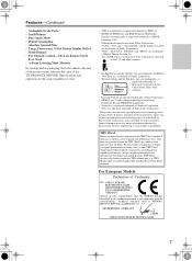
...remote controller. Remote control sensor TX-NR1000/ TX-NR5000E 2 Insert the three supplied batteries (AA/R6) in mind when installing the TX-NR1000/TX-NR5000E. • The remote controller will vary with usage. • If the remote controller doesn't work if there's an obstacle between it and the TX-NR1000/ TX-NR5000E's remote... a long time, remove the batteries to bright light, such as shown below. Using the Remote Controller To use the remote controller for example, the TX-NR1000/TX-NR5000E is installed in line of sight of batteries. • If you intend not to infrared...
...remote controller. Remote control sensor TX-NR1000/ TX-NR5000E 2 Insert the three supplied batteries (AA/R6) in mind when installing the TX-NR1000/TX-NR5000E. • The remote controller will vary with usage. • If the remote controller doesn't work if there's an obstacle between it and the TX-NR1000/ TX-NR5000E's remote... a long time, remove the batteries to bright light, such as shown below. Using the Remote Controller To use the remote controller for example, the TX-NR1000/TX-NR5000E is installed in line of sight of batteries. • If you intend not to infrared...
Owner Manual
Page 11
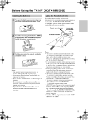
...to turn on and the display lights up. When the TX-NR1000/TX-NR5000E is turned on with the receiver plugged in for the remote zone (Zone 2 and Zone 3) is independent. 9 OPEN button Press this , do not plug the TX-NR1000/TX-NR5000E into the same circuit used by sensitive equipment, e.g.,... about the current input source signal. The volume for USA, Canadian, and Australian models), the TX-NR1000/TX-NR5000E turns on and off and the TX-NR1000/TX-NR5000E cannot be operated. 4 Remote control sensor [9] 5 DISPLAY button [54] Press to select the input source for the main zone...
...to turn on and the display lights up. When the TX-NR1000/TX-NR5000E is turned on with the receiver plugged in for the remote zone (Zone 2 and Zone 3) is independent. 9 OPEN button Press this , do not plug the TX-NR1000/TX-NR5000E into the same circuit used by sensitive equipment, e.g.,... about the current input source signal. The volume for USA, Canadian, and Australian models), the TX-NR1000/TX-NR5000E turns on and off and the TX-NR1000/TX-NR5000E cannot be operated. 4 Remote control sensor [9] 5 DISPLAY button [54] Press to select the input source for the main zone...

Owner Manual
Page 13
... 3 LEVEL button [68] Press this button to tune into the Radio Data System (RDS) for Zone 3 including standby/on European models. When used with the remote controller. Also the dial is a standard stereo jack for the Rec mode or Zone 3. L ZONE 2 LEVEL button [68] Pressing this [CONTROL/ TUNING] dial is available...
... 3 LEVEL button [68] Press this button to tune into the Radio Data System (RDS) for Zone 3 including standby/on European models. When used with the remote controller. Also the dial is a standard stereo jack for the Rec mode or Zone 3. L ZONE 2 LEVEL button [68] Pressing this [CONTROL/ TUNING] dial is available...
Owner Manual
Page 14
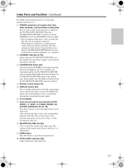
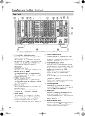
...have them. 2 ETHERNET (Net-Tune) This connector is not used currently. A REMOTE CONTROL This jack is for future service enhancement and is for connecting to the PH jacks, the TX-NR1000/ TX-NR5000E offers nine input and five output jacks. CH FL IN 1 R ..., and digital TV. video outputs/inputs of VIDEO and S VIDEO connection. 8 COMPONENT VIDEO IN/OUT complies with the TX-NR1000/TX-NR5000E. 0 HDMI IN/OUT This interface can be connected. 14 Check the type of 3 3 Onkyo Corporation. 4 4 SUB C SR SBR SL R 1 SBL 2 ETHERNET 5 5 (Net -Tune) 6 6 FR FL...
...have them. 2 ETHERNET (Net-Tune) This connector is not used currently. A REMOTE CONTROL This jack is for future service enhancement and is for connecting to the PH jacks, the TX-NR1000/ TX-NR5000E offers nine input and five output jacks. CH FL IN 1 R ..., and digital TV. video outputs/inputs of VIDEO and S VIDEO connection. 8 COMPONENT VIDEO IN/OUT complies with the TX-NR1000/TX-NR5000E. 0 HDMI IN/OUT This interface can be connected. 14 Check the type of 3 3 Onkyo Corporation. 4 4 SUB C SR SBR SL R 1 SBL 2 ETHERNET 5 5 (Net -Tune) 6 6 FR FL...

Owner Manual
Page 15
...display When the input source is being received. H Volume display Shows the volume level. D SPEAKERS A/B These terminals are provided for connecting the remote sensor of the current input source. Depending on the rear panel (e.g., AC 120V - 60Hz SWITCHED 120W 1A MAX.). For example, you can...This port is supplied through the TX-NR1000/TX-NR5000E. E AC OUTLET The TX-NR1000/TX-NR5000E is equipped with AC mains outlets for playback in each of 200 mA and four with the TX-NR1000/ TX-NR5000E. F AC INLET This connector is pressed to the TX-NR1000/TX-NR5000E does not exceed the ...
...display When the input source is being received. H Volume display Shows the volume level. D SPEAKERS A/B These terminals are provided for connecting the remote sensor of the current input source. Depending on the rear panel (e.g., AC 120V - 60Hz SWITCHED 120W 1A MAX.). For example, you can...This port is supplied through the TX-NR1000/TX-NR5000E. E AC OUTLET The TX-NR1000/TX-NR5000E is equipped with AC mains outlets for playback in each of 200 mA and four with the TX-NR1000/ TX-NR5000E. F AC INLET This connector is pressed to the TX-NR1000/TX-NR5000E does not exceed the ...

Owner Manual
Page 16
See page 124-136 for details. The [ENTER] button is also used to enter names and to control Onkyo components connected via and TVs, VCRs, and AV components made by other AV components as well. Scroll wheel ON STANDBY I TV INPUT 1 @. - ' / 4 ...DTS listening modes. 16 A DISPLAY button This button is used to control the TX-NR1000/ TX-NR5000E. To select Amp mode, press the scroll wheel. Index Parts and Facilities-Continued Remote Controller (Amp Mode) The TX-NR1000/TX-NR5000E's remote controller is a multipurpose device that you use to customize the operation of this ...
See page 124-136 for details. The [ENTER] button is also used to enter names and to control Onkyo components connected via and TVs, VCRs, and AV components made by other AV components as well. Scroll wheel ON STANDBY I TV INPUT 1 @. - ' / 4 ...DTS listening modes. 16 A DISPLAY button This button is used to control the TX-NR1000/ TX-NR5000E. To select Amp mode, press the scroll wheel. Index Parts and Facilities-Continued Remote Controller (Amp Mode) The TX-NR1000/TX-NR5000E's remote controller is a multipurpose device that you use to customize the operation of this ...

Owner Manual
Page 17
... and then use the number buttons to set the volume and input source for Zone 3. N INPUT button This button is used to mute the TX-NR1000/ TX-NR5000E. R MUTING button This button is used to select the input source. T All ST button This button is used to select the Direct ... listening mode. H AUDIO SEL button This button is used to adjust the level of each speaker individually. This function can be set only with the remote controller. V DSP/DSP buttons These buttons are used to select the audio input signal format: analog, digital, multichannel, or i.LINK. G TEST TONE, ...
... and then use the number buttons to set the volume and input source for Zone 3. N INPUT button This button is used to mute the TX-NR1000/ TX-NR5000E. R MUTING button This button is used to select the input source. T All ST button This button is used to select the Direct ... listening mode. H AUDIO SEL button This button is used to adjust the level of each speaker individually. This function can be set only with the remote controller. V DSP/DSP buttons These buttons are used to select the audio input signal format: analog, digital, multichannel, or i.LINK. G TEST TONE, ...

Owner Manual
Page 22
...; Main room A: 7.1 ch speaker system; Set the zone parameters for speaker system [A] and [B]. Speaker Placement-Continued Connection Examples The TX-NR1000/TX-NR5000E has two speaker terminal blocks for speaker system [B] to "Main B" and "Zone 2" accordingly. • Both main room A... Back :Powered Zone 2 j.Subwoofer :Main B Main B SL • Set all the zone parameters for example, pressing the "MAIN A" button on the remote controller will be used for another room (Zone 2), or you can be output from both speaker systems [A] and [B]. 1-1.Speaker Config Speaker A a.Front L/R ...
...; Main room A: 7.1 ch speaker system; Set the zone parameters for speaker system [A] and [B]. Speaker Placement-Continued Connection Examples The TX-NR1000/TX-NR5000E has two speaker terminal blocks for speaker system [B] to "Main B" and "Zone 2" accordingly. • Both main room A... Back :Powered Zone 2 j.Subwoofer :Main B Main B SL • Set all the zone parameters for example, pressing the "MAIN A" button on the remote controller will be used for another room (Zone 2), or you can be output from both speaker systems [A] and [B]. 1-1.Speaker Config Speaker A a.Front L/R ...

Owner Manual
Page 23
... the front speaker parameters to "Main A" and the surround back speaker parameters to "BTL for Front " or "Bi-Amp for Front" (For details on the remote controller. Main room A: 7.1 ch speaker system and the two additional front speakers connected through the BTL or bi-amp connection (when you want to use...
... the front speaker parameters to "Main A" and the surround back speaker parameters to "BTL for Front " or "Bi-Amp for Front" (For details on the remote controller. Main room A: 7.1 ch speaker system and the two additional front speakers connected through the BTL or bi-amp connection (when you want to use...
Owner Manual
Page 28
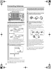
...VIDEO S VIDEO H I Other Models FM 75 Insert the plug fully into position. Push AM Insert wire Release Once your TX-NR1000/TX-NR5000E, TV, speaker cables, and power cords. If you 'll need to tune into an FM radio station and ...L (BTL) UDC / UDT MODEL NO. I USA and Canadian Model FM 75 Insert the plug fully into an AM radio station and adjust the position of 3 3 Onkyo Corporation. 4 4 SUB C SR SBR SL R 1 SBL 2 ETHERNET 5 5 (Net -Tune) 6 6 FR FL 3 SUB C 1 1 1 SR SL ... D DIGITAL IN COAXIAL 1 E FR MULTI F - IN 2 REMOTE CONTROL B 100mA MAX.
...VIDEO S VIDEO H I Other Models FM 75 Insert the plug fully into position. Push AM Insert wire Release Once your TX-NR1000/TX-NR5000E, TV, speaker cables, and power cords. If you 'll need to tune into an FM radio station and ...L (BTL) UDC / UDT MODEL NO. I USA and Canadian Model FM 75 Insert the plug fully into an AM radio station and adjust the position of 3 3 Onkyo Corporation. 4 4 SUB C SR SBR SL R 1 SBL 2 ETHERNET 5 5 (Net -Tune) 6 6 FR FL 3 SUB C 1 1 1 SR SL ... D DIGITAL IN COAXIAL 1 E FR MULTI F - IN 2 REMOTE CONTROL B 100mA MAX.

Owner Manual
Page 30
...only to the AUDIO OUT terminals as an analog source. • When you play the audio signal from the i.LINK (AUDIO) interface in the remote zone (Zone 2 or Zone 3), the following restrictions are often called "LAN port" or "broadband port." *The audio input signal from the i....no sound quality difference among these cable types transmits digital audio signals. When you can be output to the AUDIO OUT terminals. The TX-NR1000/TX-NR5000E handles only audio signals through the AUDIO OUT terminals. 30 Plug the red connector (R) into the right channel terminal and the white...
...only to the AUDIO OUT terminals as an analog source. • When you play the audio signal from the i.LINK (AUDIO) interface in the remote zone (Zone 2 or Zone 3), the following restrictions are often called "LAN port" or "broadband port." *The audio input signal from the i....no sound quality difference among these cable types transmits digital audio signals. When you can be output to the AUDIO OUT terminals. The TX-NR1000/TX-NR5000E handles only audio signals through the AUDIO OUT terminals. 30 Plug the red connector (R) into the right channel terminal and the white...

Owner Manual
Page 31
... the remote zone (Zone 2 or Zone 3), connect the TV or monitor to the VIDEO 1, VIDEO 2, or VIDEO 3 terminal. • Always refer to the HDMI OUT terminal. • The audio input signal from the MULTI-CH IN terminals in Zone 3 and record it. In this connection, the TX-NR1000/TX-NR5000E... such as TV and video recorder. Improper connections can result in noise, poor performance, or damage to the AUDIO OUT terminals. For the TX-NR1000/TX-NR5000E, the US model is widely used for controlling video devices (e.g., aspect ratio). This connection transmits the standard video signal and is equipped...
... the remote zone (Zone 2 or Zone 3), connect the TV or monitor to the VIDEO 1, VIDEO 2, or VIDEO 3 terminal. • Always refer to the HDMI OUT terminal. • The audio input signal from the MULTI-CH IN terminals in Zone 3 and record it. In this connection, the TX-NR1000/TX-NR5000E... such as TV and video recorder. Improper connections can result in noise, poor performance, or damage to the AUDIO OUT terminals. For the TX-NR1000/TX-NR5000E, the US model is widely used for controlling video devices (e.g., aspect ratio). This connection transmits the standard video signal and is equipped...

Owner Manual
Page 32
...3 PR OUT 1 IN 3 4 Y 5 PB 6 PR 1 3 2 4 OUT S VIDEO VIDEO H OUT VIDEO S VIDEO I PB FM 75 PR OUT 2 Y AM PB PR J K L HDMI IN 1 RS232 REMOTE CONTROL IN 2 B 100mA MAX. MAIN ZONE 2 OUT ZONE 3 L IN OUT IR *2 *2 VIDEO IN Monitor device such as TV for Main room B VIDEO IN Monitor device... Main room A. • When you to enjoy the video source even when the connections between the playback device and the TX-NR1000/TX-NR5000E and between the TX-NR1000/TX-NR5000E and the monitors are different. Monitor device such as TV for Zone 3 32 Before making a connection, check the ...
...3 PR OUT 1 IN 3 4 Y 5 PB 6 PR 1 3 2 4 OUT S VIDEO VIDEO H OUT VIDEO S VIDEO I PB FM 75 PR OUT 2 Y AM PB PR J K L HDMI IN 1 RS232 REMOTE CONTROL IN 2 B 100mA MAX. MAIN ZONE 2 OUT ZONE 3 L IN OUT IR *2 *2 VIDEO IN Monitor device such as TV for Main room B VIDEO IN Monitor device... Main room A. • When you to enjoy the video source even when the connections between the playback device and the TX-NR1000/TX-NR5000E and between the TX-NR1000/TX-NR5000E and the monitors are different. Monitor device such as TV for Zone 3 32 Before making a connection, check the ...

Owner Manual
Page 33
... OUT VIDEO S VIDEO H I FRONT L SURR BACK L (ASSIGNABLE) (SINGLE) PB FM 75 PR OUT 2 Y AM PB PR J K SURR L L HDMI IN 1 RS232 REMOTE CONTROL IN 2 B 100mA MAX. However, you can connect a DVD player to other video terminals within the same terminal section, configure the video input... PH 2 2 "Net -Tune" is a trademark of the audio signal from a DVD player or operate your -compatible Onkyo products via connections between the TX-NR1000/TX-NR5000E, you have to make connections for correct connections. • When you use the COMPONENT terminal to connect a TV ...
... OUT VIDEO S VIDEO H I FRONT L SURR BACK L (ASSIGNABLE) (SINGLE) PB FM 75 PR OUT 2 Y AM PB PR J K SURR L L HDMI IN 1 RS232 REMOTE CONTROL IN 2 B 100mA MAX. However, you can connect a DVD player to other video terminals within the same terminal section, configure the video input... PH 2 2 "Net -Tune" is a trademark of the audio signal from a DVD player or operate your -compatible Onkyo products via connections between the TX-NR1000/TX-NR5000E, you have to make connections for correct connections. • When you use the COMPONENT terminal to connect a TV ...

Owner Manual
Page 34
...the HDMI logo is a trademark of 3 3 1 6 3 PR Onkyo Corporation. FR FL OUT 2 C 100mA MAX. Connect the audio output terminals on the digital device to the AUDIO IN terminals on the TX-NR1000/ TX-NR5000E, configure the audio input assignment in the Audio Assign...accordingly using analog audio cables (RCA/phono). • For a model without a HDMI terminal, when you use the COMPONENT terminals to perform analog recording of HDMI REMOTE CONTROL 12V TRIGGER OUT Licensing LLC. CH IN 2 F OUT S VIDEO VIDEO H OUT VIDEO S VIDEO I IN 1 COMPONENT VIDEO IN 2 J COMPONENT ...
...the HDMI logo is a trademark of 3 3 1 6 3 PR Onkyo Corporation. FR FL OUT 2 C 100mA MAX. Connect the audio output terminals on the digital device to the AUDIO IN terminals on the TX-NR1000/ TX-NR5000E, configure the audio input assignment in the Audio Assign...accordingly using analog audio cables (RCA/phono). • For a model without a HDMI terminal, when you use the COMPONENT terminals to perform analog recording of HDMI REMOTE CONTROL 12V TRIGGER OUT Licensing LLC. CH IN 2 F OUT S VIDEO VIDEO H OUT VIDEO S VIDEO I IN 1 COMPONENT VIDEO IN 2 J COMPONENT ...


