
Owner Manual
Page 5
...follow the polarity diagram (positive (+) and negative (-) symbols) inside the battery compartment. 3. Remote control sensor TX-DS595 STANDBY indicator 30˚ 30˚ VOLTAGE SELECTOR 120V 220-230V Installing the remote controller batteries 1. After batteries are equipped with a voltage selector to match the voltage of .... 5 Slide the switch all the way to the upper (120 V) or to avoid damage from the remote controller. If the remote controller does not operate smoothly, replace both the batteries at the same time. • The life of batteries. • To avoid corrosion,...
...follow the polarity diagram (positive (+) and negative (-) symbols) inside the battery compartment. 3. Remote control sensor TX-DS595 STANDBY indicator 30˚ 30˚ VOLTAGE SELECTOR 120V 220-230V Installing the remote controller batteries 1. After batteries are equipped with a voltage selector to match the voltage of .... 5 Slide the switch all the way to the upper (120 V) or to avoid damage from the remote controller. If the remote controller does not operate smoothly, replace both the batteries at the same time. • The life of batteries. • To avoid corrosion,...

Owner Manual
Page 10
...components to the TX-DS595 in noise, poor performance, or damage to the equipment. Optical digital input terminal An optical digital input terminal is equipped with z terminals [13] ANTENNA AM MONITOR DVD OUT IN VIDEO 1 OUT IN VIDEO 2 VIDEO 3 IN IN VIDEO FM 75 REMOTE CONTROL S ... have been made. • For input jacks, red connectors (marked R) are used for the right channel, white connectors (marked L) are used , replace the protective cap. • When using , put the cap back on the terminal. When connecting, remove this cap. Connecting antennas [17] Connecting your...
...components to the TX-DS595 in noise, poor performance, or damage to the equipment. Optical digital input terminal An optical digital input terminal is equipped with z terminals [13] ANTENNA AM MONITOR DVD OUT IN VIDEO 1 OUT IN VIDEO 2 VIDEO 3 IN IN VIDEO FM 75 REMOTE CONTROL S ... have been made. • For input jacks, red connectors (marked R) are used for the right channel, white connectors (marked L) are used , replace the protective cap. • When using , put the cap back on the terminal. When connecting, remove this cap. Connecting antennas [17] Connecting your...
Owner Manual
Page 51
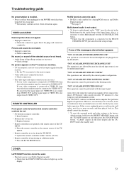
... not connected securely. © Check connections. • The video input and output connections are plugged into the TX-DS595. If this listening mode. DS595. • Remote controller is too far from an external source or static electricity may cause faulty operation. OTHER LATE NIGHT function cannot...out. © Replace batteries. • Remote controller is not heard. • Audio Setup of the Input Setup. "NOT AVAILABLE IN THIS SP CONFIG" The operation is connected to the factory default settings, hold down the PRESET MEMORY button with the TX-DS595 turned on extremely ...
... not connected securely. © Check connections. • The video input and output connections are plugged into the TX-DS595. If this listening mode. DS595. • Remote controller is too far from an external source or static electricity may cause faulty operation. OTHER LATE NIGHT function cannot...out. © Replace batteries. • Remote controller is not heard. • Audio Setup of the Input Setup. "NOT AVAILABLE IN THIS SP CONFIG" The operation is connected to the factory default settings, hold down the PRESET MEMORY button with the TX-DS595 turned on extremely ...


