Owner Manual
Page 1
... to RDS broadcasts (European models only 23 Enjoying music or videos with TX-DS595 ... 25 Using listening mode 28 Input Setup 29 Preference 32 Recording 33 Remote controller Using remote controller 34 Learning a pre-programming code 38 Operating your new AV Receiver. Following the instructions in this manual thoroughly before making connections and plugging in the unit. Please read this manual will enable you for other devices into the remote controller ..... 42 Using a Macro function 45 Appendix Specifications 49 Troubleshooting guide 50
... to RDS broadcasts (European models only 23 Enjoying music or videos with TX-DS595 ... 25 Using listening mode 28 Input Setup 29 Preference 32 Recording 33 Remote controller Using remote controller 34 Learning a pre-programming code 38 Operating your new AV Receiver. Following the instructions in this manual thoroughly before making connections and plugging in the unit. Please read this manual will enable you for other devices into the remote controller ..... 42 Using a Macro function 45 Appendix Specifications 49 Troubleshooting guide 50
Owner Manual
Page 3
... can radiate radio frequency energy and, if not installed and used meets the required voltage (e.g., AC 230 V, 50 Hz or AC 120 V, 60 Hz) written on the rear panel of this switch to which is not user-serviceable. Do not use is no guarantee that to match the voltage of the copyright holder. 3. FCC Information for User CAUTION: The user changes or modifications...
... can radiate radio frequency energy and, if not installed and used meets the required voltage (e.g., AC 230 V, 50 Hz or AC 120 V, 60 Hz) written on the rear panel of this switch to which is not user-serviceable. Do not use is no guarantee that to match the voltage of the copyright holder. 3. FCC Information for User CAUTION: The user changes or modifications...

Owner Manual
Page 5
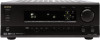
... the polarity diagram (positive (+) and negative (-) symbols) inside the battery compartment. 3. If the preset voltage is not correct for your area: 220-230 V or 120 V. ANTENNA AM MONITOR DVD OUT IN VIDEO 1 OUT IN VIDEO 2 VIDEO 3 IN IN VIDEO FM 75 REMOTE CONTROL S VIDEO PHONO CD OUT TAPE IN L L R R GND FRONT SURR CENTER L OPTICAL 1 2 COAXIAL 1 SUBWOOFER PRE OUT R SUB MULTI WOOFER CHANNEL INPUT 2 DIGITAL INPUT FRONT SPEAKERS A R L CENTER SPEAKER SURROUND SPEAKERS R L AC OUTLETS SWITCHED TOTAL 100W MAX. Remote control sensor TX-DS595 STANDBY indicator...
... the polarity diagram (positive (+) and negative (-) symbols) inside the battery compartment. 3. If the preset voltage is not correct for your area: 220-230 V or 120 V. ANTENNA AM MONITOR DVD OUT IN VIDEO 1 OUT IN VIDEO 2 VIDEO 3 IN IN VIDEO FM 75 REMOTE CONTROL S VIDEO PHONO CD OUT TAPE IN L L R R GND FRONT SURR CENTER L OPTICAL 1 2 COAXIAL 1 SUBWOOFER PRE OUT R SUB MULTI WOOFER CHANNEL INPUT 2 DIGITAL INPUT FRONT SPEAKERS A R L CENTER SPEAKER SURROUND SPEAKERS R L AC OUTLETS SWITCHED TOTAL 100W MAX. Remote control sensor TX-DS595 STANDBY indicator...
Owner Manual
Page 7
... speakers systems A and B. Input source buttons (DVD, VIDEO 1-3, TAPE, FM, AM, PHONO, and CD) [25] These buttons are 3 settings available: normal, dark, and very dark. DISPLAY button [26] The DISPLAY button is received from "AUTO" → "MULTICH" → "ANALOG" and back. Each time you press the display button, the screen changes to a radio station that you different information concerning the input signal. The tuner frequency is displayed in the standby state and flashes when a signal is used to display information about the current input source signal. PRESET / buttons...
... speakers systems A and B. Input source buttons (DVD, VIDEO 1-3, TAPE, FM, AM, PHONO, and CD) [25] These buttons are 3 settings available: normal, dark, and very dark. DISPLAY button [26] The DISPLAY button is received from "AUTO" → "MULTICH" → "ANALOG" and back. Each time you press the display button, the screen changes to a radio station that you different information concerning the input signal. The tuner frequency is displayed in the standby state and flashes when a signal is used to display information about the current input source signal. PRESET / buttons...
Owner Manual
Page 8
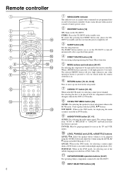
... operation button is to turn the power completely off automatically after a specified time period. TOP MENU: When in the standby state. LEVEL /ANGLE and LEVEL /SUBTITLE buttons LEVEL / : Select the speaker whose volume is pressed to tell you to set the TX-DS595 to be preprogrammed for selecting one level in the DVD or CD modes. Remote controller 1 2 3 4 5 6 7 8 9 0 A B C SEND / LEARN PREPROGRAMMED & LEARNING CAPABILITY SLEEP ON STDBY DIRECT RCVR SAT MACRO MODE CD DVD CABLE VCR RETURN SETUP MODE...
... operation button is to turn the power completely off automatically after a specified time period. TOP MENU: When in the standby state. LEVEL /ANGLE and LEVEL /SUBTITLE buttons LEVEL / : Select the speaker whose volume is pressed to tell you to set the TX-DS595 to be preprogrammed for selecting one level in the DVD or CD modes. Remote controller 1 2 3 4 5 6 7 8 9 0 A B C SEND / LEARN PREPROGRAMMED & LEARNING CAPABILITY SLEEP ON STDBY DIRECT RCVR SAT MACRO MODE CD DVD CABLE VCR RETURN SETUP MODE...
Owner Manual
Page 9
... the selected input source set in conjunction with the TX-DS595, TUN:FM/AM, PH:PHONO. For Dolby Pro Logic II, this button displays the DVD menu. Press the TEST button to enter and exit the setup mode. Same as shown below. SETUP button [19, 20, 30-32] Press to exit the setting. On: Select to calibrate the speakers levels. 1. At this button in the Listening Mode Preset is the same level. Repeat the procedure in the setup mode. Remote controller Selects an input source.
... the selected input source set in conjunction with the TX-DS595, TUN:FM/AM, PH:PHONO. For Dolby Pro Logic II, this button displays the DVD menu. Press the TEST button to enter and exit the setup mode. Same as shown below. SETUP button [19, 20, 30-32] Press to exit the setting. On: Select to calibrate the speakers levels. 1. At this button in the Listening Mode Preset is the same level. Repeat the procedure in the setup mode. Remote controller Selects an input source.

Owner Manual
Page 10
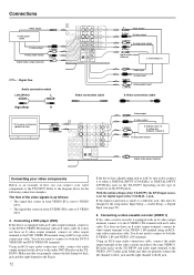
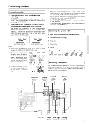
...-DS595 in the standard manner. Connections Here is explanation of how to connect the main components to devices with z terminals [13] ANTENNA AM MONITOR DVD OUT IN VIDEO 1 OUT IN VIDEO 2 VIDEO 3 IN IN VIDEO FM 75 REMOTE CONTROL S VIDEO PHONO CD OUT TAPE IN L L R R GND FRONT SURR CENTER L OPTICAL 1 2 COAXIAL 1 SUBWOOFER PRE OUT R SUB MULTI WOOFER CHANNEL INPUT 2 DIGITAL INPUT Connecting speakers [15] Cautions regarding the AC OUTLETS connectors [14] FRONT SPEAKERS A R L CENTER SPEAKER SURROUND SPEAKERS R L FRONT SPEAKERS B AV RECEIVER MODEL...
...-DS595 in the standard manner. Connections Here is explanation of how to connect the main components to devices with z terminals [13] ANTENNA AM MONITOR DVD OUT IN VIDEO 1 OUT IN VIDEO 2 VIDEO 3 IN IN VIDEO FM 75 REMOTE CONTROL S VIDEO PHONO CD OUT TAPE IN L L R R GND FRONT SURR CENTER L OPTICAL 1 2 COAXIAL 1 SUBWOOFER PRE OUT R SUB MULTI WOOFER CHANNEL INPUT 2 DIGITAL INPUT Connecting speakers [15] Cautions regarding the AC OUTLETS connectors [14] FRONT SPEAKERS A R L CENTER SPEAKER SURROUND SPEAKERS R L FRONT SPEAKERS B AV RECEIVER MODEL...

Owner Manual
Page 11
...Turntable (PHONO) Digital audio output (optical) Analog audio output L (White) R (Red) Ground wire (earth) Analog audio input 3. Tape deck, MD recorder, DAT deck, CD recorder, (TAPE) L (White) R (Red) L (White) R (Red) Analog audio output Audio connection cable Left (White) L Right (Red) R ANTENNA AM MONITOR DVD OUT IN VIDEO 1 OUT IN VIDEO 2 VIDEO IN IN FM 75 REMOTE CONTROL PHONO CD OUT TAPE IN L R GND FRONT SURR CENTER L OPTICAL 1 2 COAXIAL 1 SUBWOOFER PRE OUT R SUB MULTI WOOFER CHANNEL INPUT 2 DIGITAL INPUT Connecting your audio components to the R jack...
...Turntable (PHONO) Digital audio output (optical) Analog audio output L (White) R (Red) Ground wire (earth) Analog audio input 3. Tape deck, MD recorder, DAT deck, CD recorder, (TAPE) L (White) R (Red) L (White) R (Red) Analog audio output Audio connection cable Left (White) L Right (Red) R ANTENNA AM MONITOR DVD OUT IN VIDEO 1 OUT IN VIDEO 2 VIDEO IN IN FM 75 REMOTE CONTROL PHONO CD OUT TAPE IN L R GND FRONT SURR CENTER L OPTICAL 1 2 COAXIAL 1 SUBWOOFER PRE OUT R SUB MULTI WOOFER CHANNEL INPUT 2 DIGITAL INPUT Connecting your audio components to the R jack...
Owner Manual
Page 12
... MONITOR DVD OUT IN VIDEO 1 OUT IN VIDEO 2 VIDEO 3 IN IN VIVDIEDOEO REMOTE CONTROL NO CD OUT TAPE IN FRONT SURR CENTER L OPTICAL 1 2 COAXIAL 1 R SUB ER MULTI WOOFER UT CHANNEL INPUT 2 DIGITAL INPUT S VSIDVEIODEO L RR : Signal flow Audio connection cable Left (White) L Video connection cable V S video Video output S video output L (White) Analog audio output R (Red) Digital audio output (Coaxial) 5. Refer to the audio DVD IN jacks on the TXDS595. Connecting a DVD player (DVD) If the device is equipped with an S video cable. Using an RCA-type audio connection...
... MONITOR DVD OUT IN VIDEO 1 OUT IN VIDEO 2 VIDEO 3 IN IN VIVDIEDOEO REMOTE CONTROL NO CD OUT TAPE IN FRONT SURR CENTER L OPTICAL 1 2 COAXIAL 1 R SUB ER MULTI WOOFER UT CHANNEL INPUT 2 DIGITAL INPUT S VSIDVEIODEO L RR : Signal flow Audio connection cable Left (White) L Video connection cable V S video Video output S video output L (White) Analog audio output R (Red) Digital audio output (Coaxial) 5. Refer to the audio DVD IN jacks on the TXDS595. Connecting a DVD player (DVD) If the device is equipped with an S video cable. Using an RCA-type audio connection...
Owner Manual
Page 13
... connect to the MONITOR OUT S VIDEO terminal with an S video cable. If it to either a DIGITAL INPUT (COAXIAL) or DIGITAL INPUT (OPTICAL) jack on the TX-DS595 depending on the type of connector on the TX-DS595, switch the Input Selector from TAPE to both the S VIDEO 3 IN and VIDEO 3 IN terminals. If the power cord for an z-connected component is for no digital input. REMOTE CONTROL z connector TX-DS595 Ex: Onkyo CD player z connector Ex: Onkyo cassette tape deck To connect components using the z terminal, simply connect a remote control cable...
... connect to the MONITOR OUT S VIDEO terminal with an S video cable. If it to either a DIGITAL INPUT (COAXIAL) or DIGITAL INPUT (OPTICAL) jack on the TX-DS595 depending on the type of connector on the TX-DS595, switch the Input Selector from TAPE to both the S VIDEO 3 IN and VIDEO 3 IN terminals. If the power cord for an z-connected component is for no digital input. REMOTE CONTROL z connector TX-DS595 Ex: Onkyo CD player z connector Ex: Onkyo cassette tape deck To connect components using the z terminal, simply connect a remote control cable...
Owner Manual
Page 15
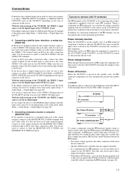
... Connecting a subwoofer Use the PRE OUT SUBWOOFER jack to connect a subwoofer with an impedance of the speakers being connected. Subwoofer Center Front right Front left speaker ANTENNA AM MONITOR DVD OUT IN VIDEO 1 OUT IN VIDEO 2 VIDEO 3 IN IN VIDEO FM 75 REMOTE CONTROL S VIDEO PHONO CD OUT TAPE IN L L R R GND FRONT SURR CENTER L OPTICAL 1 2 COAXIAL 1 SUBWOOFER PRE OUT R SUB MULTI WOOFER CHANNEL INPUT 2 DIGITAL INPUT FRONT SPEAKERS A R L CENTER SPEAKER SURROUND SPEAKERS R L FRONT SPEAKERS B AV RECEIVER MODEL NO. Connecting speakers Connecting...
... Connecting a subwoofer Use the PRE OUT SUBWOOFER jack to connect a subwoofer with an impedance of the speakers being connected. Subwoofer Center Front right Front left speaker ANTENNA AM MONITOR DVD OUT IN VIDEO 1 OUT IN VIDEO 2 VIDEO 3 IN IN VIDEO FM 75 REMOTE CONTROL S VIDEO PHONO CD OUT TAPE IN L L R R GND FRONT SURR CENTER L OPTICAL 1 2 COAXIAL 1 SUBWOOFER PRE OUT R SUB MULTI WOOFER CHANNEL INPUT 2 DIGITAL INPUT FRONT SPEAKERS A R L CENTER SPEAKER SURROUND SPEAKERS R L FRONT SPEAKERS B AV RECEIVER MODEL NO. Connecting speakers Connecting...
Owner Manual
Page 16
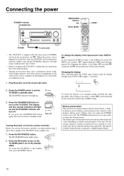
... the TAPE jack on climate and placement of the memory during power failures and even when the POWER switch is shipped with other electrical equipment on the TX-DS595. Connecting the power STANDBY indicator STANDBY/ON STANDBY/ON STANDBY POWER ON OFF PHONES DISPLAY RT/PTY/TP FM MODE PRESET MEMORY TUNING A SPEAKERS B CH LEVEL DSP/MODE ADJ SETUP PRESET RETURN PUSH TO ENTER SMART SCAN NAVIGATOR AUDIO SELECTOR DVD VIDEO 1 VIDEO 2 VIDEO 3 VCR TAPE FM AM PHONO C D MASTER VOLUME BASS TREBLE AV RECEIVER TX-DS595 POWER To...
... the TAPE jack on climate and placement of the memory during power failures and even when the POWER switch is shipped with other electrical equipment on the TX-DS595. Connecting the power STANDBY indicator STANDBY/ON STANDBY/ON STANDBY POWER ON OFF PHONES DISPLAY RT/PTY/TP FM MODE PRESET MEMORY TUNING A SPEAKERS B CH LEVEL DSP/MODE ADJ SETUP PRESET RETURN PUSH TO ENTER SMART SCAN NAVIGATOR AUDIO SELECTOR DVD VIDEO 1 VIDEO 2 VIDEO 3 VCR TAPE FM AM PHONO C D MASTER VOLUME BASS TREBLE AV RECEIVER TX-DS595 POWER To...
Owner Manual
Page 19
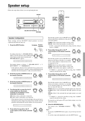
...: Select when a subwoofer is large sized. Speaker setup Follow the steps below the jog dial are lit, turning the jog dial selects a group of settings and pushing the jog dial enters the selected group (i.e. SETUP STANDBY/ON STANDBY POWER ON OFF PHONES DISPLAY RT/PTY/TP FM MODE PRESET MEMORY TUNING A SPEAKERS B CH LEVEL DSP/MODE ADJ SETUP PRESET RETURN PUSH TO ENTER SMART SCAN NAVIGATOR AUDIO SELECTOR DVD VIDEO 1 VIDEO 2 VIDEO 3 VCR TAPE FM AM PHONO C D MASTER VOLUME BASS TREBLE AV RECEIVER TX-DS595...
...: Select when a subwoofer is large sized. Speaker setup Follow the steps below the jog dial are lit, turning the jog dial selects a group of settings and pushing the jog dial enters the selected group (i.e. SETUP STANDBY/ON STANDBY POWER ON OFF PHONES DISPLAY RT/PTY/TP FM MODE PRESET MEMORY TUNING A SPEAKERS B CH LEVEL DSP/MODE ADJ SETUP PRESET RETURN PUSH TO ENTER SMART SCAN NAVIGATOR AUDIO SELECTOR DVD VIDEO 1 VIDEO 2 VIDEO 3 VCR TAPE FM AM PHONO C D MASTER VOLUME BASS TREBLE AV RECEIVER TX-DS595...
Owner Manual
Page 26
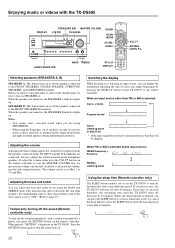
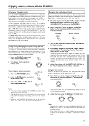
...FRONT SPEAKERS, CENTER SPEAKER, SURROUND SPEAKERS, and SUBWOOFER terminals. Switching the display While listening to turn off the speakers connected to turn the MASTER VOLUME dial. Enjoying music or videos with the TX-DS595 DISPLAY SPEAKERS A/B MASTER VOLUME Jog dial CH LEVEL STANDBY/ON STANDBY POWER ON OFF PHONES DISPLAY DIMMER FM MODE PRESET MEMORY TUNING A SPEAKERS B CH LEVEL DSP/MODE ADJ SETUP PRESET RETURN PUSH TO ENTER SMART SCAN NAVIGATOR AUDIO SELECTOR DVD VIDEO 1 VIDEO 2 VIDEO 3 VCR TAPE FM AM PHONO C D MASTER VOLUME BASS TREBLE AV RECEIVER TX-DS595...
...FRONT SPEAKERS, CENTER SPEAKER, SURROUND SPEAKERS, and SUBWOOFER terminals. Switching the display While listening to turn off the speakers connected to turn the MASTER VOLUME dial. Enjoying music or videos with the TX-DS595 DISPLAY SPEAKERS A/B MASTER VOLUME Jog dial CH LEVEL STANDBY/ON STANDBY POWER ON OFF PHONES DISPLAY DIMMER FM MODE PRESET MEMORY TUNING A SPEAKERS B CH LEVEL DSP/MODE ADJ SETUP PRESET RETURN PUSH TO ENTER SMART SCAN NAVIGATOR AUDIO SELECTOR DVD VIDEO 1 VIDEO 2 VIDEO 3 VCR TAPE FM AM PHONO C D MASTER VOLUME BASS TREBLE AV RECEIVER TX-DS595...
Owner Manual
Page 27
... TREBLE dials work for the component with the MASTER VOLUME dial or the VOL buttons on the connected component and start playing the desired media. 4. MULTICH: Select this setting to play back the input from a source component connected to "AUTO." Each channel can be adjusted between -12 to "YES." For the front right, front left, center, surround right, and surround left speakers, the output levels can be output. Turn the tone control on by the listening position. • If the speaker level...
... TREBLE dials work for the component with the MASTER VOLUME dial or the VOL buttons on the connected component and start playing the desired media. 4. MULTICH: Select this setting to play back the input from a source component connected to "AUTO." Each channel can be adjusted between -12 to "YES." For the front right, front left, center, surround right, and surround left speakers, the output levels can be output. Turn the tone control on by the listening position. • If the speaker level...
Owner Manual
Page 28
... 5.1channel* surround sound. If you connect the player to 20 kHz) channels (left and right channels (3 stereo). The 5.1- Before using a listening mode, make sure the Speaker Setup parameters have been set, it will be made for the VIDEO 1 OUT and TAPE OUT output analog audio signals. This source signal comes from DTS to PCM, the PCM signal may hear noise when you play five full-range (20 Hz to the TX-DS595 digitally. This is immediately switched from DVDs and LDs...
... 5.1channel* surround sound. If you connect the player to 20 kHz) channels (left and right channels (3 stereo). The 5.1- Before using a listening mode, make sure the Speaker Setup parameters have been set, it will be made for the VIDEO 1 OUT and TAPE OUT output analog audio signals. This source signal comes from DTS to PCM, the PCM signal may hear noise when you play five full-range (20 Hz to the TX-DS595 digitally. This is immediately switched from DVDs and LDs...
Owner Manual
Page 29
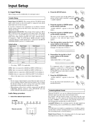
...TX-DS595 DVD VIDEO 1 VIDEO 2 VIDEO 3 VCR TAPE FM AM PHONO C D Remote controller SETUP 2. Turn the jog dial or press the or cursor button on the rear panel. "MULTICH=YES" or "NO" appears. DSP/MODE ADJ PUSH TO ENTER 7. RETURN "AUDIO SETUP?" To exit the setup mode immediately, press SETUP the SETUP button. However, the set differently for the input source. Input Setup These settings can be set listening mode is actually connected to DIGITAL INPUT (COAXIAL) 2. ----: Select if the input source is selected at the front panel for each input source. Default setting Input source DVD...
...TX-DS595 DVD VIDEO 1 VIDEO 2 VIDEO 3 VCR TAPE FM AM PHONO C D Remote controller SETUP 2. Turn the jog dial or press the or cursor button on the rear panel. "MULTICH=YES" or "NO" appears. DSP/MODE ADJ PUSH TO ENTER 7. RETURN "AUDIO SETUP?" To exit the setup mode immediately, press SETUP the SETUP button. However, the set differently for the input source. Input Setup These settings can be set listening mode is actually connected to DIGITAL INPUT (COAXIAL) 2. ----: Select if the input source is selected at the front panel for each input source. Default setting Input source DVD...
Owner Manual
Page 37
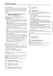
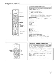
... MODE CD DVD CABLE VCR MODE MD TV RETURN SETUP C H DISC VOL AUDIO TOCPHMSEENLU TMEESNTU MUTING ANGLE SUBTITLE TV / VCR LEVEL VCR TV VOL MUTING SAT, CABLE, VCR, and TV MODE buttons No preset codes are programmed into this remote controller (see page 38). The buttons shaded in the SAT, CABLE and VCR mode, you may also use the following buttons: VOL : Adjusts the volume at the TX-DS595 MUTING: Activates the muting function at the TX-DS595...
... MODE CD DVD CABLE VCR MODE MD TV RETURN SETUP C H DISC VOL AUDIO TOCPHMSEENLU TMEESNTU MUTING ANGLE SUBTITLE TV / VCR LEVEL VCR TV VOL MUTING SAT, CABLE, VCR, and TV MODE buttons No preset codes are programmed into this remote controller (see page 38). The buttons shaded in the SAT, CABLE and VCR mode, you may also use the following buttons: VOL : Adjusts the volume at the TX-DS595 MUTING: Activates the muting function at the TX-DS595...
Owner Manual
Page 50
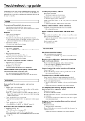
... turned up an outdoor AM antenna. Buzzing noise on AM stations (particularly noticeable at very low volume. • Speaker cable is not connected. © Check the connection between the amplifier and the speaker. • Listening mode is set to "NO." © Check the speaker setting (page 19). • Subwoofer speakers output level setting is improper. © Check the output level of the Subwoofer using the remote controller, first try to operate the controls on but sound is distorted and stereo...
... turned up an outdoor AM antenna. Buzzing noise on AM stations (particularly noticeable at very low volume. • Speaker cable is not connected. © Check the connection between the amplifier and the speaker. • Listening mode is set to "NO." © Check the speaker setting (page 19). • Subwoofer speakers output level setting is improper. © Check the output level of the Subwoofer using the remote controller, first try to operate the controls on but sound is distorted and stereo...
Owner Manual
Page 51
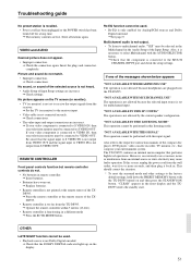
... signal input to the receiver input. • Video cable is not connected securely. © Check connections. • The video input and output connections are plugged into the TX-DS595. "NOT AVAILABLE WITH MULTICHANNEL USE" The operation is not allowed because the selected input source is set to receive the output signals from the receiver. © Set the TV (or monitor) to VIDEO IN is recalled. • Power cord has been unplugged or the POWER switch has been turned off for Analog/PCM sources and Dolby Digital surround...
... signal input to the receiver input. • Video cable is not connected securely. © Check connections. • The video input and output connections are plugged into the TX-DS595. "NOT AVAILABLE WITH MULTICHANNEL USE" The operation is not allowed because the selected input source is set to receive the output signals from the receiver. © Set the TV (or monitor) to VIDEO IN is recalled. • Power cord has been unplugged or the POWER switch has been turned off for Analog/PCM sources and Dolby Digital surround...


