
Owner Manual
Page 1
...manual for purchasing the Onkyo AV Receiver. Operation Speaker setup 14 Selecting a sound source 17 Using Listening Mode 21 Tuning in this manual will enable you for future reference. Following the instructions in a radio station 24 Using preset radio stations 25 Receiving...11 Making antenna connections .......... 12 Thank you to obtain optimum performance and listening enjoyment from your new AV Receiver. AV Receiver TX-DS575X Instruction Manual Contents Before using Important Safeguards 2 Precautions 3 Features 4 Supplied accessories 4 Before operating this unit 5 ...
...manual for purchasing the Onkyo AV Receiver. Operation Speaker setup 14 Selecting a sound source 17 Using Listening Mode 21 Tuning in this manual will enable you for future reference. Following the instructions in a radio station 24 Using preset radio stations 25 Receiving...11 Making antenna connections .......... 12 Thank you to obtain optimum performance and listening enjoyment from your new AV Receiver. AV Receiver TX-DS575X Instruction Manual Contents Before using Important Safeguards 2 Precautions 3 Features 4 Supplied accessories 4 Before operating this unit 5 ...
Owner Manual
Page 3
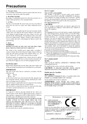
...CLASSE B EST CONFORME À LA NORME NMB-003 DU CANADA. Declaration of Conformity We, ONKYO EUROPE ELECTRONICS GmbH INDUSTRIESTRASSE 20 82110 GERMERING, GERMANY declare in own responsibility, that to which the receiver is provided to call the CATV system installer's attention to local power supplies. AC Fuse ... Blue : Neutral Brown : Live As the colours of the wires in the mains lead of this unit will not occur in this instruction manual is marked with the coloured markings identifying the terminals in a weak solution of mild detergent and water, wring it is not user-serviceable....
...CLASSE B EST CONFORME À LA NORME NMB-003 DU CANADA. Declaration of Conformity We, ONKYO EUROPE ELECTRONICS GmbH INDUSTRIESTRASSE 20 82110 GERMERING, GERMANY declare in own responsibility, that to which the receiver is provided to call the CATV system installer's attention to local power supplies. AC Fuse ... Blue : Neutral Brown : Live As the colours of the wires in the mains lead of this unit will not occur in this instruction manual is marked with the coloured markings identifying the terminals in a weak solution of mild detergent and water, wring it is not user-serviceable....
Owner Manual
Page 6
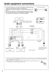
...8226; Remove the protective cap attached to the equipment. When this receiver. Remember that improper connection can be used , replace the protective cap. 6 L (Left) L • Please refer to the left channel. TX-DS575X Ground OUTPUT Turntable INPUT (REC) OUTPUT (PLAY) Tape Deck :... red connector (marked R) corresponds to the right Audio connection cable channel, and a white connector (marked L) to the instruction manual of each component when making the connec- CD Player OUTPUT (ANALOG) DIGITAL COAXIAL OUTPUT DIGITAL OPTICAL OUTPUT See page 7 Improper ...
...8226; Remove the protective cap attached to the equipment. When this receiver. Remember that improper connection can be used , replace the protective cap. 6 L (Left) L • Please refer to the left channel. TX-DS575X Ground OUTPUT Turntable INPUT (REC) OUTPUT (PLAY) Tape Deck :... red connector (marked R) corresponds to the right Audio connection cable channel, and a white connector (marked L) to the instruction manual of each component when making the connec- CD Player OUTPUT (ANALOG) DIGITAL COAXIAL OUTPUT DIGITAL OPTICAL OUTPUT See page 7 Improper ...
Owner Manual
Page 7
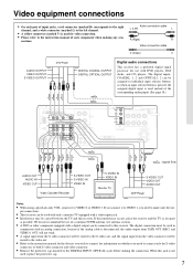
... R Video connection cable V (Video) V AUDIO OUTPUT VIDEO OUTPUT S-VIDEO OUTPUT DVD Player DIGITAL COAXIAL OUTPUT DIGITAL OPTICAL OUTPUT Digital audio connections This receiver has a powerful digital signal processor for use of input jacks, a red connector (marked R) corresponds to the right channel, and a white connector ...to the instruction manual for the devices you need to connect only the S-video connector, or both S-video connector and video connector. • Remove the protective cap attached to the DIGITAL INPUT (OPTICAL) jack before making any con- TX-DS575X : signal flow...
... R Video connection cable V (Video) V AUDIO OUTPUT VIDEO OUTPUT S-VIDEO OUTPUT DVD Player DIGITAL COAXIAL OUTPUT DIGITAL OPTICAL OUTPUT Digital audio connections This receiver has a powerful digital signal processor for use of input jacks, a red connector (marked R) corresponds to the right channel, and a white connector ...to the instruction manual for the devices you need to connect only the S-video connector, or both S-video connector and video connector. • Remove the protective cap attached to the DIGITAL INPUT (OPTICAL) jack before making any con- TX-DS575X : signal flow...
Owner Manual
Page 8
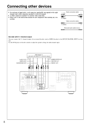
AV RECEIVER MODEL NO. DVD player or a decoder with 5.1 channel output You may connect the 5.1 channel outputs of an external decoder (such as MPEG decoder) to the MULTI CHANNEL INPUTs of this unit. TX-DS575X 8 Connecting other devices • On each pair of input jacks, a red ...for multi-channel input. Use the DVD player or decoder controls to adjust the speaker settings for video connection. • Please refer to the instruction manual of each component when making any con- Audio connection cable L (Left) L R (Right) R Video connection cable V (Video) V Monaural audio...
AV RECEIVER MODEL NO. DVD player or a decoder with 5.1 channel output You may connect the 5.1 channel outputs of an external decoder (such as MPEG decoder) to the MULTI CHANNEL INPUTs of this unit. TX-DS575X 8 Connecting other devices • On each pair of input jacks, a red ...for multi-channel input. Use the DVD player or decoder controls to adjust the speaker settings for video connection. • Please refer to the instruction manual of each component when making any con- Audio connection cable L (Left) L R (Right) R Video connection cable V (Video) V Monaural audio...
Owner Manual
Page 11
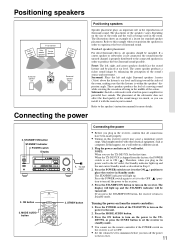
...the size of the TX-DS575X to turn off the power to place the receiver in order to the unit. 2. Surround: Place the left , right, and center speakers should be turned off the power to the speaker's instruction manual for the first time: When the TX-DS575X is shipped from the... factory, the POWER switch is set the receiver in standby mode. • You cannot use a wall outlet on this receiver's power may cause a momentary power surge, which ...
...the size of the TX-DS575X to turn off the power to place the receiver in order to the unit. 2. Surround: Place the left , right, and center speakers should be turned off the power to the speaker's instruction manual for the first time: When the TX-DS575X is shipped from the... factory, the POWER switch is set the receiver in standby mode. • You cannot use a wall outlet on this receiver's power may cause a momentary power surge, which ...
Owner Manual
Page 24
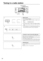
... Select the station to which you tune in AM each time will be heard. The FM MUTE indicator turns off. If the signal is received, scanning stops. In this time, the station will be impossible to tune in as follows: Frequency (preset No.) ↔ Listening mode ...EQ LFE LEVEL CONTROL MULTI CH INPUT DVD VIDEO 1 VIDEO 2 VIDEO 3 TAPE FM AM PHONO C D DOWN MASTER VOLUME UP BASS TREBLE AV RECEIVER TX-DS575X DISPLAY FM AM 1 FM AM 2 DOWN TUNING UP Manual tuning 1. UP the frequency increases. ch Listening to change the indication DISPLAY as follows.
... Select the station to which you tune in AM each time will be heard. The FM MUTE indicator turns off. If the signal is received, scanning stops. In this time, the station will be impossible to tune in as follows: Frequency (preset No.) ↔ Listening mode ...EQ LFE LEVEL CONTROL MULTI CH INPUT DVD VIDEO 1 VIDEO 2 VIDEO 3 TAPE FM AM PHONO C D DOWN MASTER VOLUME UP BASS TREBLE AV RECEIVER TX-DS575X DISPLAY FM AM 1 FM AM 2 DOWN TUNING UP Manual tuning 1. UP the frequency increases. ch Listening to change the indication DISPLAY as follows.
Owner Manual
Page 29
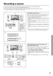
...and recording on the VCR. • Refer to the Video equipment connections section on the tape deck. • Please read the corresponding instruction manuals for the source you want to record. 3. UP UP Recording a source • You can be recorded. • You cannot record audio... EFFECT Re-EQ LFE LEVEL CONTROL MULTI CH INPUT DVD VIDEO 1 VIDEO 2 VIDEO 3 TAPE FM AM PHONO C D DOWN MASTER VOLUME BASS TREBLE AV RECEIVER TX-DS575X 1·3 Tape deck (TAPE) 3 Turntable CD player VCR, VDP DVD 2 DVD VIDEO 1 VIDEO 2 VIDEO 3 Recording an audio source Make all connections...
...and recording on the VCR. • Refer to the Video equipment connections section on the tape deck. • Please read the corresponding instruction manuals for the source you want to record. 3. UP UP Recording a source • You can be recorded. • You cannot record audio... EFFECT Re-EQ LFE LEVEL CONTROL MULTI CH INPUT DVD VIDEO 1 VIDEO 2 VIDEO 3 TAPE FM AM PHONO C D DOWN MASTER VOLUME BASS TREBLE AV RECEIVER TX-DS575X 1·3 Tape deck (TAPE) 3 Turntable CD player VCR, VDP DVD 2 DVD VIDEO 1 VIDEO 2 VIDEO 3 Recording an audio source Make all connections...
Owner Manual
Page 30
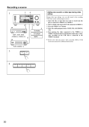
...Insert the disc or tape that is connected to the VIDEO 1 terminal. • Refer to the video disc player, video camcorder, DVD or VCR instruction manuals for additional information. 4 TAPE FM AM PHONO C D 30 Recording a source 1 STANDBY/ON STANDBY POWER ON OFF A SPEAKERS B PHONES 3 4 ...EFFECT Re-EQ LFE LEVEL CONTROL MULTI CH INPUT DVD VIDEO 1 VIDEO 2 VIDEO 3 TAPE FM AM PHONO C D DOWN MASTER VOLUME UP BASS TREBLE AV RECEIVER TX-DS575X 1·5 VDP, VCR, DVD (VIDEO 2, VIDEO 3) 2·5 5 Turntable CD player TAPE VCR (VIDEO 1) 3 VIDEO 2 VIDEO 3 Adding new sound...
...Insert the disc or tape that is connected to the VIDEO 1 terminal. • Refer to the video disc player, video camcorder, DVD or VCR instruction manuals for additional information. 4 TAPE FM AM PHONO C D 30 Recording a source 1 STANDBY/ON STANDBY POWER ON OFF A SPEAKERS B PHONES 3 4 ...EFFECT Re-EQ LFE LEVEL CONTROL MULTI CH INPUT DVD VIDEO 1 VIDEO 2 VIDEO 3 TAPE FM AM PHONO C D DOWN MASTER VOLUME UP BASS TREBLE AV RECEIVER TX-DS575X 1·5 VDP, VCR, DVD (VIDEO 2, VIDEO 3) 2·5 5 Turntable CD player TAPE VCR (VIDEO 1) 3 VIDEO 2 VIDEO 3 Adding new sound...
Owner Manual
Page 40
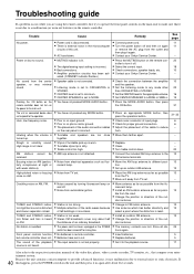
...sure that compose your entertainment system. Rough or scratchy sound. AM stations cannot be received. TUNED and STEREO indicators light but sound is distorted and stereo separation is heard ... Because the unit contains a microcomputer to provide advanced functions, it again. • Contact your Onkyo Service Center. • Press the MUTING button on FM. Howling when the volume is not set...unit and then press it is not clear. door antenna. • Change to the respective instruction manuals of the out- High range is not due to the operation. tion. • Set up...
...sure that compose your entertainment system. Rough or scratchy sound. AM stations cannot be received. TUNED and STEREO indicators light but sound is distorted and stereo separation is heard ... Because the unit contains a microcomputer to provide advanced functions, it again. • Contact your Onkyo Service Center. • Press the MUTING button on FM. Howling when the volume is not set...unit and then press it is not clear. door antenna. • Change to the respective instruction manuals of the out- High range is not due to the operation. tion. • Set up...


