Installation Guide
Page 5
... this Guide Uses 14 Notices 14 Command-Line Conventions 14 Text Conventions 15 Related Documentation 16 1 Overview 17 About the Nokia IP390 Appliance 17 Built-In Gigabit Ethernet Ports 18 PMC Expansion Slots 19 System Status LEDs 19 Managing the IP390 Appliance 20 Site Requirements, Warnings, and Cautions 21 Software Requirements 22 Product Disposal 22 2 Installing the Nokia IP390 Appliance...
... this Guide Uses 14 Notices 14 Command-Line Conventions 14 Text Conventions 15 Related Documentation 16 1 Overview 17 About the Nokia IP390 Appliance 17 Built-In Gigabit Ethernet Ports 18 PMC Expansion Slots 19 System Status LEDs 19 Managing the IP390 Appliance 20 Site Requirements, Warnings, and Cautions 21 Software Requirements 22 Product Disposal 22 2 Installing the Nokia IP390 Appliance...
Installation Guide
Page 6
4 About IP390 Appliance Network Interface Cards 37 Four-Port 10/100 Mbps Ethernet Network Interface Card 37 Ethernet ... T1 Network Interface Card 45 T1 NIC Features 45 T1 Connectors and Cables 45 5 Installing and Replacing Network Interface Cards 49 Deactivating Configured Interfaces 49 Removing, Installing, and Replacing NICs 50 Before You Start 50 Configuring and Activating Interfaces 55 Monitoring Network... 82 A Technical Specifications 87 Physical Dimensions 87 Space Requirements 87 Operating Temperature 87 NIC Interfaces 88 6 IP390 Security Platform Installation Guide
4 About IP390 Appliance Network Interface Cards 37 Four-Port 10/100 Mbps Ethernet Network Interface Card 37 Ethernet ... T1 Network Interface Card 45 T1 NIC Features 45 T1 Connectors and Cables 45 5 Installing and Replacing Network Interface Cards 49 Deactivating Configured Interfaces 49 Removing, Installing, and Replacing NICs 50 Before You Start 50 Configuring and Activating Interfaces 55 Monitoring Network... 82 A Technical Specifications 87 Physical Dimensions 87 Space Requirements 87 Operating Temperature 87 NIC Interfaces 88 6 IP390 Security Platform Installation Guide

Installation Guide
Page 11
... 2 Component Locations Rear View 18 Figure 3 Built-In Gigabit Ethernet Ports Details 18 Figure 4 Appliance Status LEDs 20 Figure 5 Mounting Screws Location 24 Figure 6 Adjustable Mounting Brackets 24 Figure 7 Back Panel Power Switch and Socket 25 Figure 8 Nokia Network Voyager Reference Access Points 35 Figure 9 Four-Port Ethernet NIC Front Panel Details... Cable Pin Connections 46 Figure 21 Compact Flash Memory Card Slot 58 Figure 22 Hard-Disk Drive Location 62 Figure 23 DIMM Socket Locations 67 IP390 Security Platform Installation Guide 11
... 2 Component Locations Rear View 18 Figure 3 Built-In Gigabit Ethernet Ports Details 18 Figure 4 Appliance Status LEDs 20 Figure 5 Mounting Screws Location 24 Figure 6 Adjustable Mounting Brackets 24 Figure 7 Back Panel Power Switch and Socket 25 Figure 8 Nokia Network Voyager Reference Access Points 35 Figure 9 Four-Port Ethernet NIC Front Panel Details... Cable Pin Connections 46 Figure 21 Compact Flash Memory Card Slot 58 Figure 22 Hard-Disk Drive Location 62 Figure 23 DIMM Socket Locations 67 IP390 Security Platform Installation Guide 11
Installation Guide
Page 13
.... „ Chapter 4, "About IP390 Appliance Network Interface Cards" describes how to connect to these problems. „ Appendix A, "Technical Specifications" provides technical specifications such as interface characteristics. „ Appendix B, "Compliance Information" provides compliance and regulatory information. Installation and maintenance should be performed by experienced technicians or Nokia-approved service providers only. IP390 Security Platform Installation Guide 13 This preface...
.... „ Chapter 4, "About IP390 Appliance Network Interface Cards" describes how to connect to these problems. „ Appendix A, "Technical Specifications" provides technical specifications such as interface characteristics. „ Appendix B, "Compliance Information" provides compliance and regulatory information. Installation and maintenance should be performed by experienced technicians or Nokia-approved service providers only. IP390 Security Platform Installation Guide 13 This preface...
Installation Guide
Page 16
In addition to this guide and other documents shipped with your appliance, documentation for this guide in PDF on the Nokia support Web site (https:// support.nokia.com/) and on the Nokia IPSO operating system CD issued with your Nokia IP390 security platform. 1 Table 2 Text Conventions...are using „ Nokia IPSO Boot Manager Reference Guide, which describes how to use the Nokia IPSO boot manager „ Clustering Configuration Guide for the version of the Nokia IP390 Security Platform Installation Guide in PDF on the Nokia support site (https://support.nokia.com). Do not press...
In addition to this guide and other documents shipped with your appliance, documentation for this guide in PDF on the Nokia support Web site (https:// support.nokia.com/) and on the Nokia IPSO operating system CD issued with your Nokia IP390 security platform. 1 Table 2 Text Conventions...are using „ Nokia IPSO Boot Manager Reference Guide, which describes how to use the Nokia IPSO boot manager „ Clustering Configuration Guide for the version of the Nokia IP390 Security Platform Installation Guide in PDF on the Nokia support site (https://support.nokia.com). Do not press...
Installation Guide
Page 17
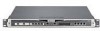
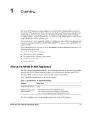
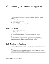
... using it. This chapter provides an overview of the IP390 appliance and the requirements for installations that want high-performance IP routing combined with your choice of firewall and VPN applications. IP390 Security Platform Installation Guide 17 The Nokia IPSO system is a one rack-unit disk-based or flash-based appliance that incorporates a serviceable slide-out tray into the...
... using it. This chapter provides an overview of the IP390 appliance and the requirements for installations that want high-performance IP routing combined with your choice of firewall and VPN applications. IP390 Security Platform Installation Guide 17 The Nokia IPSO system is a one rack-unit disk-based or flash-based appliance that incorporates a serviceable slide-out tray into the...
Installation Guide
Page 18
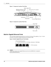
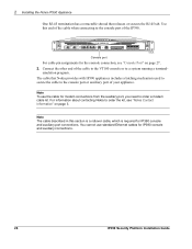
1 Overview Figure 1 Component Locations Front View System status LEDs PMC NIC slots (slots 1 and 2) unpopulated in base bundle Flash-memory PC card slots IP390 00525 Console port AUX port Reset button Four-port Gigabit Ethernet Figure 2 Component Locations Rear View Power switch 00527 Power socket Built-In Gigabit Ethernet ... Mbps) 00547 RJ-45 connectors Caution Cables that connect to the Gigabit Ethernet ports must be IEEE 802.3 compliant to prevent potential data loss. 18 IP390 Security Platform Installation Guide Figure 3 shows the layout of the appliance.
1 Overview Figure 1 Component Locations Front View System status LEDs PMC NIC slots (slots 1 and 2) unpopulated in base bundle Flash-memory PC card slots IP390 00525 Console port AUX port Reset button Four-port Gigabit Ethernet Figure 2 Component Locations Rear View Power switch 00527 Power socket Built-In Gigabit Ethernet ... Mbps) 00547 RJ-45 connectors Caution Cables that connect to the Gigabit Ethernet ports must be IEEE 802.3 compliant to prevent potential data loss. 18 IP390 Security Platform Installation Guide Figure 3 shows the layout of the appliance.
Installation Guide
Page 19
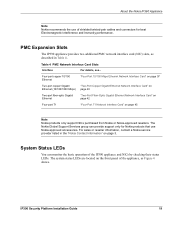
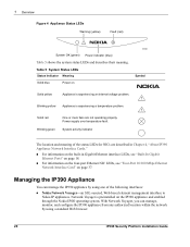
... interface card (NIC) slots, as Figure 4 shows. IP390 Security Platform Installation Guide 19 Table 4 PMC Network Interface Card Slots Interface For details, see... For sales or reseller information, contact a Nokia service provider listed in Table 4. The system status LEDs are located on the front panel of the IP390 appliance and NICs by checking their status LEDs. Four...
... interface card (NIC) slots, as Figure 4 shows. IP390 Security Platform Installation Guide 19 Table 4 PMC Network Interface Card Slots Interface For details, see... For sales or reseller information, contact a Nokia service provider listed in Table 4. The system status LEDs are located on the front panel of the IP390 appliance and NICs by checking their status LEDs. Four...
Installation Guide
Page 20
... Nokia IP appliances. Power supply over temperature fault. Network Voyager is preinstalled on 00526 Symbol Solid yellow Appliance is experiencing a temperature problem. ! 1 Overview Figure 4 Appliance Status LEDs Warning (yellow) Fault (red) ! Managing the IP390 Appliance You can manage, monitor, and configure the IP390 appliance from any authorized location within the network by using a standard Web browser. 20 IP390 Security Platform Installation Guide...
... Nokia IP appliances. Power supply over temperature fault. Network Voyager is preinstalled on 00526 Symbol Solid yellow Appliance is experiencing a temperature problem. ! 1 Overview Figure 4 Appliance Status LEDs Warning (yellow) Fault (red) ! Managing the IP390 Appliance You can manage, monitor, and configure the IP390 appliance from any authorized location within the network by using a standard Web browser. 20 IP390 Security Platform Installation Guide...
Installation Guide
Page 21
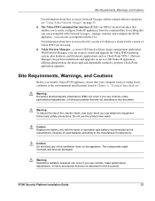
... components might overheat and become damaged. Caution Replace the battery only with the CLI. IP390 Security Platform Installation Guide 21 Caution Do not block any of used batteries according to the manufacturer's instructions. Everything that enables you to easily configure Nokia IP appliances from the command line. Site Requirements, Warnings, and Cautions For information about how...
... components might overheat and become damaged. Caution Replace the battery only with the CLI. IP390 Security Platform Installation Guide 21 Caution Do not block any of used batteries according to the manufacturer's instructions. Everything that enables you to easily configure Nokia IP appliances from the command line. Site Requirements, Warnings, and Cautions For information about how...
Installation Guide
Page 22
... to your product's Eco Declaration, which includes details about the materials used in manufacturing and end-of these products as unsorted municipal waste. 050930 22 IP390 Security Platform Installation Guide Software Requirements The Nokia IP390 appliance supports the following resources are available to you to dispose of -life practices. The following operating system and applications: „...
... to your product's Eco Declaration, which includes details about the materials used in manufacturing and end-of these products as unsorted municipal waste. 050930 22 IP390 Security Platform Installation Guide Software Requirements The Nokia IP390 appliance supports the following resources are available to you to dispose of -life practices. The following operating system and applications: „...
Installation Guide
Page 23
... are properly grounded by using a grounding wrist strap and following topics are covered: „ Before You Begin „ Rack Mounting the Appliance „ Connecting Power „ Connecting to the Console or Auxiliary Port „ Connecting to install the Nokia IP390 appliance. IP390 Security Platform Installation Guide 23 The following the instructions provided with four mounting screws as Figure 5 shows.
... are properly grounded by using a grounding wrist strap and following topics are covered: „ Before You Begin „ Rack Mounting the Appliance „ Connecting Power „ Connecting to the Console or Auxiliary Port „ Connecting to install the Nokia IP390 appliance. IP390 Security Platform Installation Guide 23 The following the instructions provided with four mounting screws as Figure 5 shows.

Installation Guide
Page 24
... Figure 7 shows. 2 Installing the Nokia IP390 Appliance Figure 5 Mounting Screws Location IP390 00525 Mounting screw slots Two mounting positions are available allowing you to mount the unit either flush with rack installation Brackets located for IP390 forward of rack installation 00539 Caution Blocking ventilation openings during installation may result in damage to 264]) and configures itself appropriately. 24 IP390 Security Platform Installation Guide
... Figure 7 shows. 2 Installing the Nokia IP390 Appliance Figure 5 Mounting Screws Location IP390 00525 Mounting screw slots Two mounting positions are available allowing you to mount the unit either flush with rack installation Brackets located for IP390 forward of rack installation 00539 Caution Blocking ventilation openings during installation may result in damage to 264]) and configures itself appropriately. 24 IP390 Security Platform Installation Guide

Installation Guide
Page 25
...a data communications equipment (DCE) device, use a straight-through cable. Use only the RJ-45 port labeled Console on the back of the appliance. 2. IP390 Security Platform Installation Guide 25 For information about using DHCP for the console: „ 9600 bps „ 8 data bits „ No parity „ 1 ...stop bit To connect to the console port on the front panel of your Nokia IP390 appliance, you no longer need the console connection. Plug ...
...a data communications equipment (DCE) device, use a straight-through cable. Use only the RJ-45 port labeled Console on the back of the appliance. 2. IP390 Security Platform Installation Guide 25 For information about using DHCP for the console: „ 9600 bps „ 8 data bits „ No parity „ 1 ...stop bit To connect to the console port on the front panel of your Nokia IP390 appliance, you no longer need the console connection. Plug ...
Installation Guide
Page 26
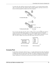
... for IP390 console and auxiliary connections. 26 IP390 Security Platform Installation Guide Note The cable described in this end of your appliance. IP390 00525 Console port For cable pin assignments for IP390 console and auxiliary port connections. The cable that releases or secures the RJ-45 tab. 2 Installing the Nokia IP390 Appliance One RJ-45 termination has a retractable shroud that Nokia provides with IP390 appliances includes...
... for IP390 console and auxiliary connections. 26 IP390 Security Platform Installation Guide Note The cable described in this end of your appliance. IP390 00525 Console port For cable pin assignments for IP390 console and auxiliary port connections. The cable that releases or secures the RJ-45 tab. 2 Installing the Nokia IP390 Appliance One RJ-45 termination has a retractable shroud that Nokia provides with IP390 appliances includes...
Installation Guide
Page 27
...Figure 6, to supply information that makes the appliance available on the boot to 9600 bps. If you need to access the devices locally, you would with other end of the serial ports are: 9600 baud, 8 bits, no parity, and 1 stop. IP390 Security Platform Installation Guide 27 To connect the cable 1 + 2 ...console port. The DB-25 adaptor is provided with Nokia modem cable kits for console connections. The DB-9 adapter is provided with the cable. The default configuration of the cable to a DB-9 console connection (using the appliance console port and the DB-9 female adaptor) or ...
...Figure 6, to supply information that makes the appliance available on the boot to 9600 bps. If you need to access the devices locally, you would with other end of the serial ports are: 9600 baud, 8 bits, no parity, and 1 stop. IP390 Security Platform Installation Guide 27 To connect the cable 1 + 2 ...console port. The DB-25 adaptor is provided with Nokia modem cable kits for console connections. The DB-9 adapter is provided with the cable. The default configuration of the cable to a DB-9 console connection (using the appliance console port and the DB-9 female adaptor) or ...
Installation Guide
Page 28
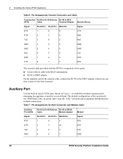
2 Installing the Nokia IP390 Appliance Table... 5 4 5 GND RxD 6 3 3 TxD DSR 7 2 4 DTR CTS 8 1 7 RTS The console cable provided with the IP390 is comprised of two parts: „ 6-foot rollover cable with RJ-45 terminations „ RJ-45 to DB-9 adapter On the opposite...appliance remotely or out-of-band. Auxiliary Port Use the built-in serial (AUX) port, shown in Figure 1, to DB-25 Cable Modem Adapter Modem Signal RJ-45 Pin RJ-45 Pin DB-25 Pin Signal RTS 1 8 4 RTS DTR 2 7 20 DTR TxD 3 6 3 TxD GND 4 5 7 GND 28 IP390 Security Platform Installation Guide...
2 Installing the Nokia IP390 Appliance Table... 5 4 5 GND RxD 6 3 3 TxD DSR 7 2 4 DTR CTS 8 1 7 RTS The console cable provided with the IP390 is comprised of two parts: „ 6-foot rollover cable with RJ-45 terminations „ RJ-45 to DB-9 adapter On the opposite...appliance remotely or out-of-band. Auxiliary Port Use the built-in serial (AUX) port, shown in Figure 1, to DB-25 Cable Modem Adapter Modem Signal RJ-45 Pin RJ-45 Pin DB-25 Pin Signal RTS 1 8 4 RTS DTR 2 7 20 DTR TxD 3 6 3 TxD GND 4 5 7 GND 28 IP390 Security Platform Installation Guide...
Installation Guide
Page 30
2 Installing the Nokia IP390 Appliance After you connect the network interfaces, continue with Chapter 3, "Performing the Initial Configuration." 30 IP390 Security Platform Installation Guide
2 Installing the Nokia IP390 Appliance After you connect the network interfaces, continue with Chapter 3, "Performing the Initial Configuration." 30 IP390 Security Platform Installation Guide
Installation Guide
Page 31
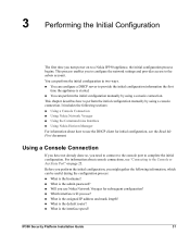
...power on page 25. This process enables you need to connect to the console port to a Nokia IP390 appliance, the initial configuration process begins. You can perform the initial configuration in two ways. „...Nokia Horizon Manager For information about console connections, see the Read Me First document. This chapter describes how to the admin account. Before you perform the initial configuration, you use the DHCP client for initial configuration, see "Connecting to the Console or Auxiliary Port" on to complete the initial configuration. IP390 Security Platform Installation Guide...
...power on page 25. This process enables you need to connect to the console port to a Nokia IP390 appliance, the initial configuration process begins. You can perform the initial configuration in two ways. „...Nokia Horizon Manager For information about console connections, see the Read Me First document. This chapter describes how to the admin account. Before you perform the initial configuration, you use the DHCP client for initial configuration, see "Connecting to the Console or Auxiliary Port" on to complete the initial configuration. IP390 Security Platform Installation Guide...

Installation Guide
Page 32
... appliance turn on power to the appliance. If the fans are running , or if the power LED does not illuminate, contact your Nokia service provider as listed in "Nokia Contact Information" on the screen for about five seconds. To perform the initial configuration 1. After some miscellaneous output, the following prompt appears: Hostname? 32 IP390 Security Platform Installation Guide...
... appliance turn on power to the appliance. If the fans are running , or if the power LED does not illuminate, contact your Nokia service provider as listed in "Nokia Contact Information" on the screen for about five seconds. To perform the initial configuration 1. After some miscellaneous output, the following prompt appears: Hostname? 32 IP390 Security Platform Installation Guide...


