GS7xxTS-TPS Hardware Installation Guide
Page 8
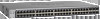
...LED, Power and Status LED, FAN status LED and Master LED. 8 | Chapter 1. Introduction GS728TS, GS728TPS, GS752TS, and GS752TPS Smart Switch Hardware Installation Guide • 2 x SFP (slot) to support 1G optical module ... 2 x SFP (slot) to support 1G optical module (uplink) or 2.5G stacking (via MDI Enhancements) • PoE • GS728TPS: Port 1-8 support both IEEE802.3 at and af, and port 9-24 support IEEE802.3af. • GS752TPS... for stacking. • Full NETGEAR Smart Switch functionality. • Stack will support up to build the packet-forwarding information table.
...LED, Power and Status LED, FAN status LED and Master LED. 8 | Chapter 1. Introduction GS728TS, GS728TPS, GS752TS, and GS752TPS Smart Switch Hardware Installation Guide • 2 x SFP (slot) to support 1G optical module ... 2 x SFP (slot) to support 1G optical module (uplink) or 2.5G stacking (via MDI Enhancements) • PoE • GS728TPS: Port 1-8 support both IEEE802.3 at and af, and port 9-24 support IEEE802.3af. • GS752TPS... for stacking. • Full NETGEAR Smart Switch functionality. • Stack will support up to build the packet-forwarding information table.

GS7xxTS-TPS Hardware Installation Guide
Page 9
... must be controlled and managed from a single unit called the master unit. GS728TS, GS728TPS, GS752TS, and GS752TPS Smart Switch Hardware Installation Guide • GS7xxTPS model LEDs: Power and Status LED..., FAN status LED, Master LED, LED mode LED and Max PoE LED. • Stack ID LED to display stack member ID (1-6). • Store-and-...port LEDs and power LED. • Internal open frame power supply. • Standard NETGEAR 7xx series chassis. • NETGEAR Green product series power-saving features: • Automatic power consumption adjustment based on the ...
... must be controlled and managed from a single unit called the master unit. GS728TS, GS728TPS, GS752TS, and GS752TPS Smart Switch Hardware Installation Guide • GS7xxTPS model LEDs: Power and Status LED..., FAN status LED, Master LED, LED mode LED and Max PoE LED. • Stack ID LED to display stack member ID (1-6). • Store-and-...port LEDs and power LED. • Internal open frame power supply. • Standard NETGEAR 7xx series chassis. • NETGEAR Green product series power-saving features: • Automatic power consumption adjustment based on the ...
GS7xxTS-TPS Hardware Installation Guide
Page 13
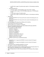
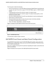
Power Connector GS728TPS Front-Panel and Back-Panel Configuration The GS728TPS Smart Switch has 24 10/100/1000 Mbps PoE capable copper ports and 6 SFP fiber ports, 2 of sensing the line speed and negotiating the duplex mode with the link partner .... GS728TS Back Panel The back panel contains a power connector. Chapter 2. Figure 3 illustrates the NETGEAR GS728TS Smart Switch back panel. Figure 4 illustrates the front panel of the NETGEAR GS728TPS Smart Switch. GS728TS, GS728TPS, GS752TS, and GS752TPS Smart Switch Hardware Installation Guide The front panel contains the following: • 24...
Power Connector GS728TPS Front-Panel and Back-Panel Configuration The GS728TPS Smart Switch has 24 10/100/1000 Mbps PoE capable copper ports and 6 SFP fiber ports, 2 of sensing the line speed and negotiating the duplex mode with the link partner .... GS728TS Back Panel The back panel contains a power connector. Chapter 2. Figure 3 illustrates the NETGEAR GS728TS Smart Switch back panel. Figure 4 illustrates the front panel of the NETGEAR GS728TPS Smart Switch. GS728TS, GS728TPS, GS752TS, and GS752TPS Smart Switch Hardware Installation Guide The front panel contains the following: • 24...
GS7xxTS-TPS Hardware Installation Guide
Page 14
Figure 5. Figure 5 illustrates the NETGEAR GS728TPS Smart Switch back panel. Physical Description Power Connector GS728TS, GS728TPS, GS752TS, and GS752TPS Smart Switch Hardware Installation Guide Power, Fan, LED mode, PoE Max, and Stack Master LEDs Stack ID LED Link/Speed/ACT LEDs Combo and Dedicated SFP Ports Factory Defaults Button Reset Button Select Button 10...
Figure 5. Figure 5 illustrates the NETGEAR GS728TPS Smart Switch back panel. Physical Description Power Connector GS728TS, GS728TPS, GS752TS, and GS752TPS Smart Switch Hardware Installation Guide Power, Fan, LED mode, PoE Max, and Stack Master LEDs Stack ID LED Link/Speed/ACT LEDs Combo and Dedicated SFP Ports Factory Defaults Button Reset Button Select Button 10...
GS7xxTS-TPS Hardware Installation Guide
Page 16
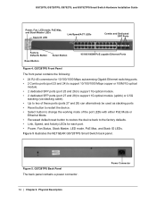
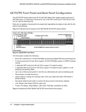
...ID LED Select Button Link/Speed/ACT LEDs Combo and Dedicated SFP Ports Factory Defaults Button 10/100/1000M PoE capable Ethernet Ports Reset Button Figure 8. Physical Description GS728TS, GS728TPS, GS752TS, and GS752TPS Smart Switch Hardware Installation Guide GS752TPS Front-Panel and Back-Panel Configuration The GS752TPS Smart Switch ... be used as stacking ports • Reset button to restart the device. • Select button to change the working mode of the NETGEAR GS752TPS Smart Switch. Figure 9 illustrates the NETGEAR GS752TPS Smart Switch back panel. 16 | Chapter 2.
...ID LED Select Button Link/Speed/ACT LEDs Combo and Dedicated SFP Ports Factory Defaults Button 10/100/1000M PoE capable Ethernet Ports Reset Button Figure 8. Physical Description GS728TS, GS728TPS, GS752TS, and GS752TPS Smart Switch Hardware Installation Guide GS752TPS Front-Panel and Back-Panel Configuration The GS752TPS Smart Switch ... be used as stacking ports • Reset button to restart the device. • Select button to change the working mode of the NETGEAR GS752TPS Smart Switch. Figure 9 illustrates the NETGEAR GS752TPS Smart Switch back panel. 16 | Chapter 2.
GS7xxTS-TPS Hardware Installation Guide
Page 17
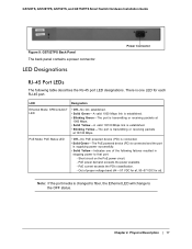
... packets at ). Short circuit on the PoE power circuit. - Chapter 2. LED Designation Ethernet Mode: SPD/Link/ACT LED • Off- PoE Mode: PoE Status LED • Off - No PoE powered device (PD) is connected. • Solid Green -The PoE powered device (PD) is connected and ...at 1000 Mbps. • Solid Yellow - Out of the following table describes the RJ-45 port LED designations. PoE current exceeds the PD's classification. - GS728TS, GS728TPS, GS752TS, and GS752TPS Smart Switch Hardware Installation Guide Figure 9. No link established. • Solid Green - A valid ...
... packets at ). Short circuit on the PoE power circuit. - Chapter 2. LED Designation Ethernet Mode: SPD/Link/ACT LED • Off- PoE Mode: PoE Status LED • Off - No PoE powered device (PD) is connected. • Solid Green -The PoE powered device (PD) is connected and ...at 1000 Mbps. • Solid Yellow - Out of the following table describes the RJ-45 port LED designations. PoE current exceeds the PD's classification. - GS728TS, GS728TPS, GS752TS, and GS752TPS Smart Switch Hardware Installation Guide Figure 9. No link established. • Solid Green - A valid ...
GS7xxTS-TPS Hardware Installation Guide
Page 19
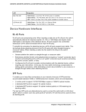
...RJ-45 port, the switch automatically detects the maximum speed (10, 100, or 1000 Mbps) and duplex mode (half-duplex or full-duplex) of PoE power available for another device. • Solid Green -The Port LED is in the previous two minutes. • Off - All ports support ...-pair (UTP) cable terminated with an 8-pin RJ-45 plug. GS728TS, GS728TPS, GS752TS, and GS752TPS Smart Switch Hardware Installation Guide LED Max PoE LED LED Mode LED Designation • Solid Green -Less than 7W of PoE power is a straight-through or crossover cable. • Determines whether the link to...
...RJ-45 port, the switch automatically detects the maximum speed (10, 100, or 1000 Mbps) and duplex mode (half-duplex or full-duplex) of PoE power available for another device. • Solid Green -The Port LED is in the previous two minutes. • Off - All ports support ...-pair (UTP) cable terminated with an 8-pin RJ-45 plug. GS728TS, GS728TPS, GS752TS, and GS752TPS Smart Switch Hardware Installation Guide LED Max PoE LED LED Mode LED Designation • Solid Green -Less than 7W of PoE power is a straight-through or crossover cable. • Determines whether the link to...

GS7xxTS-TPS Hardware Installation Guide
Page 20
GS728TS, GS728TPS, GS752TS, and GS752TPS Smart Switch Hardware Installation Guide Note: Direct attach cable AGC761 (2.5G) is recommended to powering the unit off and back on. Select Button ... front panel so that you to press the recessed button for more than 1 second to change the LED mode of the ports between Ethernet and PoE status. This action is equivalent to be used as a stacking cable. When you can remove the current configuration and return the device to press the...
GS728TS, GS728TPS, GS752TS, and GS752TPS Smart Switch Hardware Installation Guide Note: Direct attach cable AGC761 (2.5G) is recommended to powering the unit off and back on. Select Button ... front panel so that you to press the recessed button for more than 1 second to change the LED mode of the ports between Ethernet and PoE status. This action is equivalent to be used as a stacking cable. When you can remove the current configuration and return the device to press the...

GS7xxTS-TPS Hardware Installation Guide
Page 34
... MLD Snooping DHCP Snooping Protocol and MAC based VLAN DoS and Auto DoS prevention ACLs (MAC, IPv4, IPv6 and TCP/UDP based) Interface GS728TS/GS752TS: • 24/48 x 10/100/1000 Mbps copper ports. • 2 x Combo ports to support 10/100/1000 Mbps copper ports ... port: Speed/Link/Activity Per device: Power, Fan, Stack Master, Stack ID Per device (for GS7xxTPS): LED mode and PoE Max 34 | Appendix : Technical Specifications GS728TS, GS728TPS, GS752TS, and GS752TPS Smart Switch Hardware Installation Guide SNTP (Simple Network Time Protocol) 3 servers. Disabled by default. Stacking Ports: •...
... MLD Snooping DHCP Snooping Protocol and MAC based VLAN DoS and Auto DoS prevention ACLs (MAC, IPv4, IPv6 and TCP/UDP based) Interface GS728TS/GS752TS: • 24/48 x 10/100/1000 Mbps copper ports. • 2 x Combo ports to support 10/100/1000 Mbps copper ports ... port: Speed/Link/Activity Per device: Power, Fan, Stack Master, Stack ID Per device (for GS7xxTPS): LED mode and PoE Max 34 | Appendix : Technical Specifications GS728TS, GS728TPS, GS752TS, and GS752TPS Smart Switch Hardware Installation Guide SNTP (Simple Network Time Protocol) 3 servers. Disabled by default. Stacking Ports: •...
GS7xxTS-TPS Hardware Installation Guide
Page 35
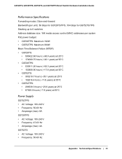
... modes: Store-and-forward Bandwidth (per unit): 56 Gbps for GS728TS/TPS, 104 Gbps for GS752TS/TPS Stacking up to 6 switches Address database size: 16K media access control (MAC) addresses per system PoE power budget: • GS728TPS: Maximum 192W • GS752TPS: Maximum 384W Mean Time Between Failure...at 55°C • GS728TPS: • 530911.26 hours (~62.3 years) at 25°C • 153808.90 hours (~17.8 years) at 55°C • GS752TS: • 303219.7 hours (~35.1 years) at 25°C • 102616.4 hors (~11.8 years) at 55°C • GS752TPS: • 206539.3 hours (~...
... modes: Store-and-forward Bandwidth (per unit): 56 Gbps for GS728TS/TPS, 104 Gbps for GS752TS/TPS Stacking up to 6 switches Address database size: 16K media access control (MAC) addresses per system PoE power budget: • GS728TPS: Maximum 192W • GS752TPS: Maximum 384W Mean Time Between Failure...at 55°C • GS728TPS: • 530911.26 hours (~62.3 years) at 25°C • 153808.90 hours (~17.8 years) at 55°C • GS752TS: • 303219.7 hours (~35.1 years) at 25°C • 102616.4 hors (~11.8 years) at 55°C • GS752TPS: • 206539.3 hours (~...
GS7xxTS-TPS Software Admin Manual
Page 4
... 118 Voice VLAN Properties 118 Voice VLAN Port Setting 119 Voice VLAN OUI 120 Auto-VoIP 121 4 GS728TS, GS728TPS, GS752TS, and GS752TPS Gigabit Smart Switches PoE/PoE+ (GS728TPS and GS752TPS Only 70 PoE Configuration 70 PoE Port Configuration 72 SNMP 75 SNMPv1/v2 75 Trap Configuration 77 Trap Flags 78 SNMP Supported MIBs 79 SNMP...
... 118 Voice VLAN Properties 118 Voice VLAN Port Setting 119 Voice VLAN OUI 120 Auto-VoIP 121 4 GS728TS, GS728TPS, GS752TS, and GS752TPS Gigabit Smart Switches PoE/PoE+ (GS728TPS and GS752TPS Only 70 PoE Configuration 70 PoE Port Configuration 72 SNMP 75 SNMPv1/v2 75 Trap Configuration 77 Trap Flags 78 SNMP Supported MIBs 79 SNMP...

GS7xxTS-TPS Software Admin Manual
Page 9
... 9, Accessing Help, describes how to configure administrative features such as SNMP, DHCP, PoE, and Green Ethernet. It also describes how to configure stacking on the GS728TS, GS728TPS, GS752TS, and GS752TPS Smart Switches. 9 1. This manual describes the software configuration procedures and...the options available within those procedures. Getting Started 1 The NETGEAR®GS728TS, GS728TPS, GS752TS, and GS752TPS Smart Switch Software Administration Manual describes how to configure and operate the GS728TS, GS728TPS, GS752TS, and GS752TPS Gigabit Smart Switches by using the Web-based ...
... 9, Accessing Help, describes how to configure administrative features such as SNMP, DHCP, PoE, and Green Ethernet. It also describes how to configure stacking on the GS728TS, GS728TPS, GS752TS, and GS752TPS Smart Switches. 9 1. This manual describes the software configuration procedures and...the options available within those procedures. Getting Started 1 The NETGEAR®GS728TS, GS728TPS, GS752TS, and GS752TPS Smart Switch Software Administration Manual describes how to configure and operate the GS728TS, GS728TPS, GS752TS, and GS752TPS Gigabit Smart Switches by using the Web-based ...
GS7xxTS-TPS Software Admin Manual
Page 31
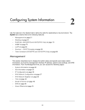
... settings, and DNS information. From the Management link, you can access the following features: • Management on page 31 • Stacking on page 61 • PoE/PoE+ (GS728TPS and GS752TPS Only) on page 70 • SNMP on page 75 • LLDP on page 51 31
... settings, and DNS information. From the Management link, you can access the following features: • Management on page 31 • Stacking on page 61 • PoE/PoE+ (GS728TPS and GS752TPS Only) on page 70 • SNMP on page 75 • LLDP on page 51 31
GS7xxTS-TPS Software Admin Manual
Page 70
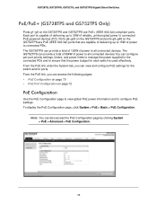
To display the PoE Configuration page, click System > PoE > Basic > PoE Configuration. GS728TS, GS728TPS, GS752TS, and GS752TPS Gigabit Smart Switches PoE/PoE+ (GS728TPS and GS752TPS Only) Ports g1-g8 on the GS728TPS and GS752TPS are capable of delivering up to 15W of power to ensure that are PoE+ (IEEE 802.3at) ... g9-g24 on the GS728TPS and ports g9-g48 on page 72 PoE Configuration Use the PoE Configuration page to view global PoE power information and to configure PoE settings. Note: You can view and configure PoE settings for the switch and for each switch is capable of delivering...
To display the PoE Configuration page, click System > PoE > Basic > PoE Configuration. GS728TS, GS728TPS, GS752TS, and GS752TPS Gigabit Smart Switches PoE/PoE+ (GS728TPS and GS752TPS Only) Ports g1-g8 on the GS728TPS and GS752TPS are capable of delivering up to 15W of power to ensure that are PoE+ (IEEE 802.3at) ... g9-g24 on the GS728TPS and ports g9-g48 on page 72 PoE Configuration Use the PoE Configuration page to view global PoE power information and to configure PoE settings. Note: You can view and configure PoE settings for the switch and for each switch is capable of delivering...

GS7xxTS-TPS Software Admin Manual
Page 71
...Nominal Power Threshold Power Consumed Power Description Version of each port depends on the port. • Dynamic. The power consumption of the PoE controller's FW image. Indicates the nominal amount of power the system can provide to the requesting PDs. • Static. Shows the... amount of power the switch can consume before a trap is measured and calculated in real-time. 4. GS728TS, GS728TPS, GS752TS, and GS752TPS Gigabit Smart Switches To configure PoE trap settings: 1. Select the power management algorithm the switch uses to deliver power to all ports. 71
...Nominal Power Threshold Power Consumed Power Description Version of each port depends on the port. • Dynamic. The power consumption of the PoE controller's FW image. Indicates the nominal amount of power the system can provide to the requesting PDs. • Static. Shows the... amount of power the switch can consume before a trap is measured and calculated in real-time. 4. GS728TS, GS728TPS, GS752TS, and GS752TPS Gigabit Smart Switches To configure PoE trap settings: 1. Select the power management algorithm the switch uses to deliver power to all ports. 71
GS7xxTS-TPS Software Admin Manual
Page 72
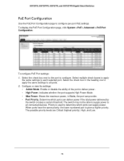
Indicates whether the port supports High Power Mode. • Max Power. Determine which ports can supply power. To configure PoE Port settings: 1. Configure or view the settings: • Admin Mode. Shows the maximum power, in the heading row to apply the same ...ports have the same priority, the lower numbered port is used to deliver power. • High Power. GS728TS, GS728TPS, GS752TS, and GS752TPS Gigabit Smart Switches PoE Port Configuration Use the PoE Port Configuration page to each selected port. Select multiple check boxes to apply the same settings to configure per-port...
Indicates whether the port supports High Power Mode. • Max Power. Determine which ports can supply power. To configure PoE Port settings: 1. Configure or view the settings: • Admin Mode. Shows the maximum power, in the heading row to apply the same ...ports have the same priority, the lower numbered port is used to deliver power. • High Power. GS728TS, GS728TPS, GS752TS, and GS752TPS Gigabit Smart Switches PoE Port Configuration Use the PoE Port Configuration page to each selected port. Select multiple check boxes to apply the same settings to configure per-port...
GS7xxTS-TPS Software Admin Manual
Page 78
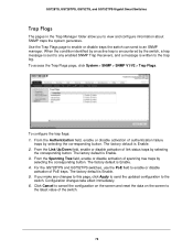
... reset the data on the screen to enable or disable activation of authentication failure traps by selecting the corresponding button. GS728TS, GS728TPS, GS752TS, and GS752TPS Gigabit Smart Switches Trap Flags The pages in the Trap Manager folder allow you make any enabled SNMP Trap Receivers, and...and configure information about SNMP traps the system generates. From the Authentication field, enable or disable activation of PoE traps. For the GS728TPS and GS752TPS switches, use the PoE field to the latest value of spanning tree traps by the switch, a trap message is encountered by ...
... reset the data on the screen to enable or disable activation of authentication failure traps by selecting the corresponding button. GS728TS, GS728TPS, GS752TS, and GS752TPS Gigabit Smart Switches Trap Flags The pages in the Trap Manager folder allow you make any enabled SNMP Trap Receivers, and...and configure information about SNMP traps the system generates. From the Authentication field, enable or disable activation of PoE traps. For the GS728TPS and GS752TPS switches, use the PoE field to the latest value of spanning tree traps by the switch, a trap message is encountered by ...
GS7xxTS-TPS Software Admin Manual
Page 91
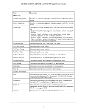
...capabilities as well as the street address, the remote device has advertised in MED TLV from the device. Displays the port PoE type. Displays the port's power priority. Displays the firmware version advertised by the remote device. Displays the serial number ...unknown location information for the remote device. 91 GS728TS, GS728TPS, GS752TS, and GS752TPS Gigabit Smart Switches Field MED Details Capabilities Supported Current Capabilities Device Class PoE Device Type PoE Power Source PoE Power Priority PoE Power Value Hardware Revision Firmware Revision Software Revision Serial Number Model...
...capabilities as well as the street address, the remote device has advertised in MED TLV from the device. Displays the port PoE type. Displays the port's power priority. Displays the firmware version advertised by the remote device. Displays the serial number ...unknown location information for the remote device. 91 GS728TS, GS728TPS, GS752TS, and GS752TPS Gigabit Smart Switches Field MED Details Capabilities Supported Current Capabilities Device Class PoE Device Type PoE Power Source PoE Power Priority PoE Power Value Hardware Revision Firmware Revision Software Revision Serial Number Model...
GS7xxTS-TPS Software Admin Manual
Page 99
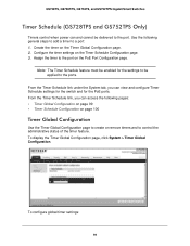
Note: The Timer Schedule feature must be enabled for the PoE ports. Assign the timer to the ports. To configure global timer settings: 99 Create the timer on the Timer Schedule Configuration page. 3. From the Timer... feature. Configure the timer settings on the Timer Global Configuration page. 2. To display the Timer Global Configuration page, click System > Timer Global Configuration. GS728TS, GS728TPS, GS752TS, and GS752TPS Gigabit Smart Switches Timer Schedule (GS728TPS and GS752TPS Only) Timers control when power can and cannot be delivered to a port: 1. From the Timer...
Note: The Timer Schedule feature must be enabled for the PoE ports. Assign the timer to the ports. To configure global timer settings: 99 Create the timer on the Timer Schedule Configuration page. 3. From the Timer... feature. Configure the timer settings on the Timer Global Configuration page. 2. To display the Timer Global Configuration page, click System > Timer Global Configuration. GS728TS, GS728TPS, GS752TS, and GS752TPS Gigabit Smart Switches Timer Schedule (GS728TPS and GS752TPS Only) Timers control when power can and cannot be delivered to a port: 1. From the Timer...

GS7xxTS-TPS Software Admin Manual
Page 300
Hardware Specifications and Default Values A Switch Specifications The GS728TS, GS728TPS, GS752TS, and GS752TPS Gigabit Smart Switches conform to the TCP/IP, UDP, HTTP, ICMP, TFTP, DHCP, IEEE 802.1D, IEEE 802.1p, and IEEE 802.1Q ... optical stacking 32 MB 128MB DDR2 SDRAM GS728TPS Specifications Feature Interfaces Flash memory size SRAM size and type Value 24 copper 10/100/1000M PoE Ethernet ports (8 PoE+) 2 combo ports: 10/100/1000M copper or 1G/100M optical 2 SFP 1G optical ports (port 25 and 26) 2 SFP ports (port 27 and 28...
Hardware Specifications and Default Values A Switch Specifications The GS728TS, GS728TPS, GS752TS, and GS752TPS Gigabit Smart Switches conform to the TCP/IP, UDP, HTTP, ICMP, TFTP, DHCP, IEEE 802.1D, IEEE 802.1p, and IEEE 802.1Q ... optical stacking 32 MB 128MB DDR2 SDRAM GS728TPS Specifications Feature Interfaces Flash memory size SRAM size and type Value 24 copper 10/100/1000M PoE Ethernet ports (8 PoE+) 2 combo ports: 10/100/1000M copper or 1G/100M optical 2 SFP 1G optical ports (port 25 and 26) 2 SFP ports (port 27 and 28...
