GS724TP User Manual
Page 37
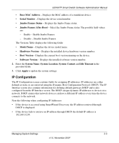
...to devices on the device. • Software Version - Select the Jumbo Frame status. Displays the installed software version number. 2. GS700TP Smart Switch Software Administration Manual • Base MAC Address - Displays the device serial number. • Jumbo Frames Status - Displays the Jumbo ...Frame status. • Jumbo Frames After Reset - Enable Jumbo Frames. - Disable Jumbo Frames. Displays the device model name. • Hardware Version - Click Apply to the network. The DHCP assigns dynamic IP addresses to retrieve...
...to devices on the device. • Software Version - Select the Jumbo Frame status. Displays the installed software version number. 2. GS700TP Smart Switch Software Administration Manual • Base MAC Address - Displays the device serial number. • Jumbo Frames Status - Displays the Jumbo ...Frame status. • Jumbo Frames After Reset - Enable Jumbo Frames. - Disable Jumbo Frames. Displays the device model name. • Hardware Version - Click Apply to the network. The DHCP assigns dynamic IP addresses to retrieve...

GS724TP Hardware manual
Page 22
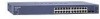
... • Device Hardware Interfaces Front and Back Panel Configuration GS724TP Front and Back Panels Configuration The GS724TP is a 24-Ports 10/100/1000M + 2 SFP Combo ports Smart PoE switch .Every RJ45 port is capable of sensing the line speed and negotiating the operation duplex mode with the link partner automatically Figure 3-1 illustrates the NETGEAR GS724TP Smart Switch front panel: Figure...
... • Device Hardware Interfaces Front and Back Panel Configuration GS724TP Front and Back Panels Configuration The GS724TP is a 24-Ports 10/100/1000M + 2 SFP Combo ports Smart PoE switch .Every RJ45 port is capable of sensing the line speed and negotiating the operation duplex mode with the link partner automatically Figure 3-1 illustrates the NETGEAR GS724TP Smart Switch front panel: Figure...

GS724TP Hardware manual
Page 23
...-Port 10/100/1000M Smart PoE switch + 4 SFP Combo port switch. Every RJ45 port is capable of sensing the line speed and negotiating the operation duplex mode with the link partner automatically Figure 3-3 illustrates the NETGEAR GS748TP Smart Switch front panel: Figure 3-3...Reset button to restart the device. • Recessed default reset button to restore the device back to the factory defaults. • Port LEDS • System LEDs Physical Description v1.0, November 2007 3-20 GS700TP Hardware Installation Guide • System LEDs Figure 3-2 illustrates the NETGEAR GS724TP Smart Switch...
...-Port 10/100/1000M Smart PoE switch + 4 SFP Combo port switch. Every RJ45 port is capable of sensing the line speed and negotiating the operation duplex mode with the link partner automatically Figure 3-3 illustrates the NETGEAR GS748TP Smart Switch front panel: Figure 3-3...Reset button to restart the device. • Recessed default reset button to restore the device back to the factory defaults. • Port LEDS • System LEDs Physical Description v1.0, November 2007 3-20 GS700TP Hardware Installation Guide • System LEDs Figure 3-2 illustrates the NETGEAR GS724TP Smart Switch...

GS724TP Hardware manual
Page 34
...100Base-TX 1-2 10Base-T 1-2 1U 1-3 8-pin 2-9 A AC Power 2-6, 2-7 AGM731F 2-10 AGM732F 2-10 AGM733 2-10 Applying AC Power 4-17 Attaching Switch to a Rack 4-15 Auto Sensing 1-2 Auto Uplink 2-9, 2-10 Auto-negotiating 1-3 Auto-sensing 2-9 B Back-pressure 1-3 Brackets 4-14 C Category 5 Unshielded...Service 1-2 Combo Port 2-10 Combo Ports 1-2 Connecting Devices to the Switch 4-16 Copper 1-1 Crossover 2-9 D Default IP Address 4-18 Default Reset Button 2-5, 2-7 Device Hardware Interfaces 2-9 Duplex Mode 2-9 E Example of Desktop Switching 3-12 F Factory Default Button 2-10 Factory Defaults 2-5 Fan LED 2-9...
...100Base-TX 1-2 10Base-T 1-2 1U 1-3 8-pin 2-9 A AC Power 2-6, 2-7 AGM731F 2-10 AGM732F 2-10 AGM733 2-10 Applying AC Power 4-17 Attaching Switch to a Rack 4-15 Auto Sensing 1-2 Auto Uplink 2-9, 2-10 Auto-negotiating 1-3 Auto-sensing 2-9 B Back-pressure 1-3 Brackets 4-14 C Category 5 Unshielded...Service 1-2 Combo Port 2-10 Combo Ports 1-2 Connecting Devices to the Switch 4-16 Copper 1-1 Crossover 2-9 D Default IP Address 4-18 Default Reset Button 2-5, 2-7 Device Hardware Interfaces 2-9 Duplex Mode 2-9 E Example of Desktop Switching 3-12 F Factory Default Button 2-10 Factory Defaults 2-5 Fan LED 2-9...


