
GS724TP User Manual
Page 9
...assumes that you can all levels. ix v1.0, December 2007 This document was created primarily for the GS700TP Smart Switch software. This book describes the software configuration procedures and explains the options available within those procedures. Once ... the full benefit of its included software. About This Manual The NETGEAR® GS700TP Smart Switch Software Administration Manual describes how to install, configure, operate, and troubleshoot the GS700TP Gigabit PoE Smart Switch using the remaining factory default parameters. Who Should Use this Book The information in a network....
...assumes that you can all levels. ix v1.0, December 2007 This document was created primarily for the GS700TP Smart Switch software. This book describes the software configuration procedures and explains the options available within those procedures. Once ... the full benefit of its included software. About This Manual The NETGEAR® GS700TP Smart Switch Software Administration Manual describes how to install, configure, operate, and troubleshoot the GS700TP Gigabit PoE Smart Switch using the remaining factory default parameters. Who Should Use this Book The information in a network....
GS724TP User Manual
Page 24
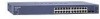
...factory default is password) and click Login. Located on the left side of the Secondary Navigation Bar. The Main Navigation Area includes Primary and Secondary Navigation Bars. The Primary Navigation Bar contains a list of the different features that can be configured as part of the NETGEAR...of features that can be expanded to display all the components. 2-2 Introduction to the view of the GS700TP Smart Switch browser interface displays. Figure 2-2 The NETGEAR GS700TP web browser interface contains the following views: Main Navigation Area - Left Navigation Tree - For each ...
...factory default is password) and click Login. Located on the left side of the Secondary Navigation Bar. The Main Navigation Area includes Primary and Secondary Navigation Bars. The Primary Navigation Bar contains a list of the different features that can be configured as part of the NETGEAR...of features that can be expanded to display all the components. 2-2 Introduction to the view of the GS700TP Smart Switch browser interface displays. Figure 2-2 The NETGEAR GS700TP web browser interface contains the following views: Main Navigation Area - Left Navigation Tree - For each ...
GS724TP User Manual
Page 91
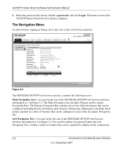
... the device. The Voice VLAN OUI screen displays. 2. To remove a Voice VLAN OUI: 1. Click RESTORE DEFAULTS to update the device. The Voice VLAN OUI screen displays. 2. Click Switching > Voice VLAN > Advanced > OUI. Enter the Telephone OUI and Description in the provided fields in the... first editable row. 5. Click Switching > Voice VLAN > Advanced > OUI. The Voice VLAN OUI screen displays. 2. GS700TP Smart Switch Software Administration Manual Voice VLAN OUI To define OUIs: 1. Click Apply to restore the factory defaults. Click Delete to remove the entry. To ...
... the device. The Voice VLAN OUI screen displays. 2. To remove a Voice VLAN OUI: 1. Click RESTORE DEFAULTS to update the device. The Voice VLAN OUI screen displays. 2. Click Switching > Voice VLAN > Advanced > OUI. Enter the Telephone OUI and Description in the provided fields in the... first editable row. 5. Click Switching > Voice VLAN > Advanced > OUI. The Voice VLAN OUI screen displays. 2. GS700TP Smart Switch Software Administration Manual Voice VLAN OUI To define OUIs: 1. Click Apply to restore the factory defaults. Click Delete to remove the entry. To ...
GS724TP User Manual
Page 118
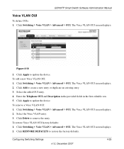
... - The CoS Interface Configuration screen displays: Figure 5-2 The CoS Interface Configuration screen contains the following: • Interface - Restore the factory CoS default settings to the ports. - Checked - GS700TP Smart Switch Software Administration Manual To configure CoS interface parameters: 1. Select the interface. 3. Displays the interface for which the global QoS parameters are : - Maintain the current...
... - The CoS Interface Configuration screen displays: Figure 5-2 The CoS Interface Configuration screen contains the following: • Interface - Restore the factory CoS default settings to the ports. - Checked - GS700TP Smart Switch Software Administration Manual To configure CoS interface parameters: 1. Select the interface. 3. Displays the interface for which the global QoS parameters are : - Maintain the current...
GS724TP User Manual
Page 122
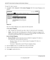
... in the provided fields. 3. Click QoS > CoS> Advanced > CoS to a forwarding queue. Restore the factory default settings for each CoS value in the provided field. 4. Four traffic priority queues are : - Maintain the current CoS queue mapping settings. 2. GS700TP Smart Switch Software Administration Manual To map CoS values to a forwarding queue. - The CoS to Queue...
... in the provided fields. 3. Click QoS > CoS> Advanced > CoS to a forwarding queue. Restore the factory default settings for each CoS value in the provided field. 4. Four traffic priority queues are : - Maintain the current CoS queue mapping settings. 2. GS700TP Smart Switch Software Administration Manual To map CoS values to a forwarding queue. - The CoS to Queue...

GS724TP User Manual
Page 124
GS700TP Smart Switch Software Administration Manual • Restore Defaults- Checked - Maintain the current DSCP mapping settings. 2. Select the Queue values for DSCP mapping values. - The possible field values are: - Click Apply to update the device. 5-10 v1.0, December 2007 Configuring QoS Restore the factory default settings for each DSCP In value in the provided field. 4. Check or uncheck the Restore Defaults box in the provided fields. 3. Restore the DSCP Mapping device factory default values. Unchecked -
GS700TP Smart Switch Software Administration Manual • Restore Defaults- Checked - Maintain the current DSCP mapping settings. 2. Select the Queue values for DSCP mapping values. - The possible field values are: - Click Apply to update the device. 5-10 v1.0, December 2007 Configuring QoS Restore the factory default settings for each DSCP In value in the provided field. 4. Check or uncheck the Restore Defaults box in the provided fields. 3. Restore the DSCP Mapping device factory default values. Unchecked -
GS724TP User Manual
Page 175
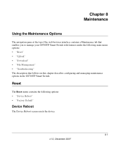
...: • "Reset" • "Upload" • "Download" • "File Management" • "Troubleshooting" The description that enables you to manage your GS700TP Smart Switch with features under the following options: • "Device Reboot" • "Factory Default" Device Reboot The Device Reboot screen resets the device. 8-1 v1.0, December 2007 Chapter 8 Maintenance Using the Maintenance Options The navigation...
...: • "Reset" • "Upload" • "Download" • "File Management" • "Troubleshooting" The description that enables you to manage your GS700TP Smart Switch with features under the following options: • "Device Reboot" • "Factory Default" Device Reboot The Device Reboot screen resets the device. 8-1 v1.0, December 2007 Chapter 8 Maintenance Using the Maintenance Options The navigation...
GS724TP User Manual
Page 176
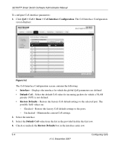
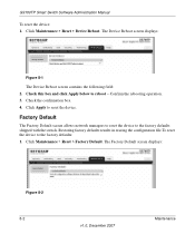
GS700TP Smart Switch Software Administration Manual To reset the device: 1. Confirm the rebooting operation. 3. Factory Default The Factory Default screen allows network managers to reset the device to reset the device. The Factory Default screen displays: Figure 8-2 8-2 v1.0, December 2007 Maintenance Check the confirmation box. 4. Click Apply to the factory defaults shipped with the switch. Click Maintenance > Reset > Factory Default. The Device Reboot screen...
GS700TP Smart Switch Software Administration Manual To reset the device: 1. Confirm the rebooting operation. 3. Factory Default The Factory Default screen allows network managers to reset the device to reset the device. The Factory Default screen displays: Figure 8-2 8-2 v1.0, December 2007 Maintenance Check the confirmation box. 4. Click Apply to the factory defaults shipped with the switch. Click Maintenance > Reset > Factory Default. The Device Reboot screen...
GS724TP User Manual
Page 177
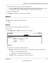
... possible field values are: - Upload the Configuration File. • via TFTP - Click Apply to reset the device to their default values after reset. 2. GS700TP Smart Switch Software Administration Manual The Factory Default screen contains the following field: • Note: all configuration settings will be restored after reset - Check the confirmation box. ... System Files can be uploaded. Select to upload the file to be backed up files: 1. Check to confirm that the original factory default values will return to the factory defaults. Firmware - Click Maintenance > Upload.
... possible field values are: - Upload the Configuration File. • via TFTP - Click Apply to reset the device to their default values after reset. 2. GS700TP Smart Switch Software Administration Manual The Factory Default screen contains the following field: • Note: all configuration settings will be restored after reset - Check the confirmation box. ... System Files can be uploaded. Select to upload the file to be backed up files: 1. Check to confirm that the original factory default values will return to the factory defaults. Firmware - Click Maintenance > Upload.
GS724TP User Manual
Page 185
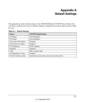
...) Auto-negotiation Disabled Disabled IP Configuration Password VLAN DHCP enabled password 802.1q based VLAN Link Aggregation (Trunk) Traffic Prioritization (QoS) Disabled Optimized for the NETGEAR Model GS700TP Smart Switch. Appendix A Default Settings This appendix provides default settings for flow control, all ports set normal priority A-1 v1.0, December 2007 Table A-1. You can always configure the...
...) Auto-negotiation Disabled Disabled IP Configuration Password VLAN DHCP enabled password 802.1q based VLAN Link Aggregation (Trunk) Traffic Prioritization (QoS) Disabled Optimized for the NETGEAR Model GS700TP Smart Switch. Appendix A Default Settings This appendix provides default settings for flow control, all ports set normal priority A-1 v1.0, December 2007 Table A-1. You can always configure the...
GS724TP Hardware manual
Page 6
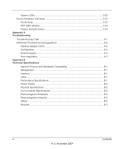
System LEDs ...3-22 Device Hardware Interfaces 3-23 RJ-45 Ports ...3-23 SFP GBIC Module 3-24 Factory Defaults Button 3-24 Appendix A Troubleshooting Troubleshooting Chart A-1 Additional Troubleshooting Suggestions A-2 Network Adapter Cards A-2 Configuration ...A-2 Switch Integrity ...A-2 Auto-negotiation ...A-3 Appendix B Technical Specifications Network Protocol and Standards Compatibility B-1 Management ...B-1 Interface ...B-1 LEDs ...B-1 Performance Specifications B-1 Power Supply ...B-2 Physical Specifications B-2 Environmental Specifications B-2 Electromagnetic...
System LEDs ...3-22 Device Hardware Interfaces 3-23 RJ-45 Ports ...3-23 SFP GBIC Module 3-24 Factory Defaults Button 3-24 Appendix A Troubleshooting Troubleshooting Chart A-1 Additional Troubleshooting Suggestions A-2 Network Adapter Cards A-2 Configuration ...A-2 Switch Integrity ...A-2 Auto-negotiation ...A-3 Appendix B Technical Specifications Network Protocol and Standards Compatibility B-1 Management ...B-1 Interface ...B-1 LEDs ...B-1 Performance Specifications B-1 Power Supply ...B-2 Physical Specifications B-2 Environmental Specifications B-2 Electromagnetic...

GS724TP Hardware manual
Page 22
... Interfaces Front and Back Panel Configuration GS724TP Front and Back Panels Configuration The GS724TP is a 24-Ports 10/100/1000M + 2 SFP Combo ports Smart PoE switch .Every RJ45 port is capable of sensing the line speed and negotiating the operation duplex mode with the link partner automatically Figure 3-1 illustrates the NETGEAR GS724TP Smart Switch front panel: Figure 3-1 The front...
... Interfaces Front and Back Panel Configuration GS724TP Front and Back Panels Configuration The GS724TP is a 24-Ports 10/100/1000M + 2 SFP Combo ports Smart PoE switch .Every RJ45 port is capable of sensing the line speed and negotiating the operation duplex mode with the link partner automatically Figure 3-1 illustrates the NETGEAR GS724TP Smart Switch front panel: Figure 3-1 The front...

GS724TP Hardware manual
Page 23
...NETGEAR GS724TP Smart Switch back panel: Figure 3-2 The back panel contains the following: • A 100-240VAC/50-60 Hz universal input, which is capable of sensing the line speed and negotiating the operation duplex mode with the link partner automatically Figure 3-3 illustrates the NETGEAR GS748TP Smart Switch... • Recessed default reset button to restore the device back to the factory defaults. • Port LEDS • System LEDs Physical Description v1.0, November 2007 3-20 GS748TP Front and Back Panels Configuration The GS748TP is a 48-Port 10/100/1000M Smart PoE switch + 4 SFP...
...NETGEAR GS724TP Smart Switch back panel: Figure 3-2 The back panel contains the following: • A 100-240VAC/50-60 Hz universal input, which is capable of sensing the line speed and negotiating the operation duplex mode with the link partner automatically Figure 3-3 illustrates the NETGEAR GS748TP Smart Switch... • Recessed default reset button to restore the device back to the factory defaults. • Port LEDS • System LEDs Physical Description v1.0, November 2007 3-20 GS748TP Front and Back Panels Configuration The GS748TP is a 48-Port 10/100/1000M Smart PoE switch + 4 SFP...
GS724TP Hardware manual
Page 26
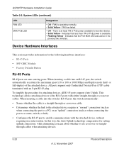
...or full-duplex) of PoE power available for the following hardware interfaces: • RJ-45 Ports • SFP GBIC Module • Factory Defaults Button RJ-45 Ports RJ-45ports are auto-sensing ports. When inserting a cable into an RJ-45 port, the switch automatically ascertains the maximum speed... (10 or 100 or 1000 Mbps) and duplex mode (half- System LEDs (continued) LED FAN LED MAX POE LED Designation •...
...or full-duplex) of PoE power available for the following hardware interfaces: • RJ-45 Ports • SFP GBIC Module • Factory Defaults Button RJ-45 Ports RJ-45ports are auto-sensing ports. When inserting a cable into an RJ-45 port, the switch automatically ascertains the maximum speed... (10 or 100 or 1000 Mbps) and duplex mode (half- System LEDs (continued) LED FAN LED MAX POE LED Designation •...

GS724TP Hardware manual
Page 27
...connection with an RJ-45 port. For example, both connectors are plugged in at the same time. Factory Defaults Button The Smart Switch has a Factory default button to enable clearing the current configuration and returning the device back to the factory settings. This removes all settings, including the password, VLAN settings and port configurations. Physical Description v1... GS700TP Hardware Installation Guide SFP GBIC Module The GBIC module bays accommodate standard SFP GBIC modules, such as the AGM731F, AGM732F, or AGM733 from NETGEAR, allowing fiber connections on the network.
...connection with an RJ-45 port. For example, both connectors are plugged in at the same time. Factory Defaults Button The Smart Switch has a Factory default button to enable clearing the current configuration and returning the device back to the factory settings. This removes all settings, including the password, VLAN settings and port configurations. Physical Description v1... GS700TP Hardware Installation Guide SFP GBIC Module The GBIC module bays accommodate standard SFP GBIC modules, such as the AGM731F, AGM732F, or AGM733 from NETGEAR, allowing fiber connections on the network.

GS724TP Hardware manual
Page 34
... 1-2 10Base-T 1-2 1U 1-3 8-pin 2-9 A AC Power 2-6, 2-7 AGM731F 2-10 AGM732F 2-10 AGM733 2-10 Applying AC Power 4-17 Attaching Switch to a Rack 4-15 Auto Sensing 1-2 Auto Uplink 2-9, 2-10 Auto-negotiating 1-3 Auto-sensing 2-9 B Back-pressure 1-3 Brackets 4-14 C Category... Port 2-10 Combo Ports 1-2 Connecting Devices to the Switch 4-16 Copper 1-1 Crossover 2-9 D Default IP Address 4-18 Default Reset Button 2-5, 2-7 Device Hardware Interfaces 2-9 Duplex Mode 2-9 E Example of Desktop Switching 3-12 F Factory Default Button 2-10 Factory Defaults 2-5 Fan LED 2-9 Fiber Connectivity 1-1 Flat Surface 4-...
... 1-2 10Base-T 1-2 1U 1-3 8-pin 2-9 A AC Power 2-6, 2-7 AGM731F 2-10 AGM732F 2-10 AGM733 2-10 Applying AC Power 4-17 Attaching Switch to a Rack 4-15 Auto Sensing 1-2 Auto Uplink 2-9, 2-10 Auto-negotiating 1-3 Auto-sensing 2-9 B Back-pressure 1-3 Brackets 4-14 C Category... Port 2-10 Combo Ports 1-2 Connecting Devices to the Switch 4-16 Copper 1-1 Crossover 2-9 D Default IP Address 4-18 Default Reset Button 2-5, 2-7 Device Hardware Interfaces 2-9 Duplex Mode 2-9 E Example of Desktop Switching 3-12 F Factory Default Button 2-10 Factory Defaults 2-5 Fan LED 2-9 Fiber Connectivity 1-1 Flat Surface 4-...


