GS716Tv2/GS724Tv3 Hardware manual
Page 1
GS716T/GS724T Hardware Installation Guide NETGEAR, Inc. 350 East Plumeria Drive San Jose, California 95134 USA 202-10510-01 June 2009 v1.0
GS716T/GS724T Hardware Installation Guide NETGEAR, Inc. 350 East Plumeria Drive San Jose, California 95134 USA 202-10510-01 June 2009 v1.0
GS716Tv2/GS724Tv3 Hardware manual
Page 2
... Family: Product Name: Home or Business Product: Language: Publication Part Number: Publication Version Number: GS716T and GS724T June 2009 GS716T/GS724T Series Smart Switch Smart Switch Business English 202-10510-01 1.0 ii v1.0, June 2009 Trademarks NETGEAR, the NETGEAR logo, and Auto Uplink are registered trademarks or trademarks of the Manufacturer/Importer It is hereby certified...
... Family: Product Name: Home or Business Product: Language: Publication Part Number: Publication Version Number: GS716T and GS724T June 2009 GS716T/GS724T Series Smart Switch Smart Switch Business English 202-10510-01 1.0 ii v1.0, June 2009 Trademarks NETGEAR, the NETGEAR logo, and Auto Uplink are registered trademarks or trademarks of the Manufacturer/Importer It is hereby certified...
GS716Tv2/GS724Tv3 Hardware manual
Page 3
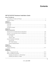
......vi Chapter 1 Introduction Overview ...1-1 Features ...1-2 Package Contents ...1-3 Chapter 2 Physical Description GS716T Front and Back Panel Configuration 2-5 GS724T Front and Back Panel Configuration 2-6 LED Designations ...2-7 Port LEDs ...2-7 System LEDs ...2-8 Device Hardware Interfaces 2-8 RJ-45 Ports ... ...2-9 Factory Defaults Button 2-9 Chapter 3 Applications Desktop Switching ...3-11 Chapter 4 Installation Step 1: Preparing the Site 4-13 Step 2: Installing the Switch 4-14 Installing the Switch on a Flat Surface 4-14 Installing the Switch in a Rack 4-14 iii v1.0, June 2009
......vi Chapter 1 Introduction Overview ...1-1 Features ...1-2 Package Contents ...1-3 Chapter 2 Physical Description GS716T Front and Back Panel Configuration 2-5 GS724T Front and Back Panel Configuration 2-6 LED Designations ...2-7 Port LEDs ...2-7 System LEDs ...2-8 Device Hardware Interfaces 2-8 RJ-45 Ports ... ...2-9 Factory Defaults Button 2-9 Chapter 3 Applications Desktop Switching ...3-11 Chapter 4 Installation Step 1: Preparing the Site 4-13 Step 2: Installing the Switch 4-14 Installing the Switch on a Flat Surface 4-14 Installing the Switch in a Rack 4-14 iii v1.0, June 2009
GS716Tv2/GS724Tv3 Hardware manual
Page 4
GS716T/GS724T Hardware Installation Guide Step 3: Checking the Installation 4-15 Step 4: Connecting Devices to the Switch 4-16 Step 5: Installing an SFP GBIC Module 4-16 Step 6: Applying AC Power 4-17 Step 7: Managing the Switch using a Web Browser or the PC Utility 4-18 Appendix A Troubleshooting Troubleshooting Chart A-19 Additional Troubleshooting Suggestions A-20 Network Adapter Cards A-20 Configuration ...A-20 Switch Integrity ...A-20 Auto-Negotiation A-21 Appendix B Technical Specifications Index iv v1.0, June 2009
GS716T/GS724T Hardware Installation Guide Step 3: Checking the Installation 4-15 Step 4: Connecting Devices to the Switch 4-16 Step 5: Installing an SFP GBIC Module 4-16 Step 6: Applying AC Power 4-17 Step 7: Managing the Switch using a Web Browser or the PC Utility 4-18 Appendix A Troubleshooting Troubleshooting Chart A-19 Additional Troubleshooting Suggestions A-20 Network Adapter Cards A-20 Configuration ...A-20 Switch Integrity ...A-20 Auto-Negotiation A-21 Appendix B Technical Specifications Index iv v1.0, June 2009

GS716Tv2/GS724Tv3 Hardware manual
Page 5
...information in this type of note may result in the following paragraphs: • Typographical Conventions. About This Manual The NETGEAR® ProSafeTM GS716T/GS724T Hardware Installation Guide describes how to highlight a procedure that will save time or resources. This manual uses the following ... described in a malfunction or damage to the equipment. Tip: This format is used to install, configure and troubleshoot the Smart Switch. This manual uses the following typographical conventions: Italic Bold Fixed italic Emphasis, books, CDs, file and server names, extensions User...
...information in this type of note may result in the following paragraphs: • Typographical Conventions. About This Manual The NETGEAR® ProSafeTM GS716T/GS724T Hardware Installation Guide describes how to highlight a procedure that will save time or resources. This manual uses the following ... described in a malfunction or damage to the equipment. Tip: This format is used to install, configure and troubleshoot the Smart Switch. This manual uses the following typographical conventions: Italic Bold Fixed italic Emphasis, books, CDs, file and server names, extensions User...
GS716Tv2/GS724Tv3 Hardware manual
Page 6
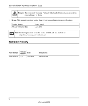
Revision History Part Number Version Number Date 202-10510-01 1.0 June 2009 Description Initial release vi v1.0, June 2009 website at http://kbserver.netgear.com/main.asp. Failure to these specifications: Product Version Manual Publication Date Smart Switch June 2009 Note: Product updates are available on the NETGEAR, Inc. GS716T/GS724T Hardware Installation Guide Danger: This is written for the Smart Switch according to take heed of this notice may result in personal injury or death. • Scope. This manual is a safety warning.
Revision History Part Number Version Number Date 202-10510-01 1.0 June 2009 Description Initial release vi v1.0, June 2009 website at http://kbserver.netgear.com/main.asp. Failure to these specifications: Product Version Manual Publication Date Smart Switch June 2009 Note: Product updates are available on the NETGEAR, Inc. GS716T/GS724T Hardware Installation Guide Danger: This is written for the Smart Switch according to take heed of this notice may result in personal injury or death. • Scope. This manual is a safety warning.
GS716Tv2/GS724Tv3 Hardware manual
Page 7
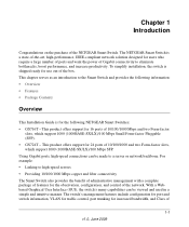
... two Form-factor slots, which support 1000 (1000BASE-SX/LX)/100 Mbps Small Form-factor Pluggable (SFP). • GS724T - Using Gigabit ports, high-speed connections can be made to the Smart Switch and provides the following NETGEAR Smart Switches: • GS716T - For example: • Linking to eliminate bottlenecks, boost performance, and increase productivity. The...
... two Form-factor slots, which support 1000 (1000BASE-SX/LX)/100 Mbps Small Form-factor Pluggable (SFP). • GS724T - Using Gigabit ports, high-speed connections can be made to the Smart Switch and provides the following NETGEAR Smart Switches: • GS716T - For example: • Linking to eliminate bottlenecks, boost performance, and increase productivity. The...
GS716Tv2/GS724Tv3 Hardware manual
Page 8
...are connected. The RJ-45 copper ports corresponding to the highest speed. GS716T/GS724T Hardware Installation Guide Service (CoS) for all RJ-45 ports operate in half-duplex or full-duplex mode. The Smart Switch can automatically negotiate to the Combo ports are supported: • 1000BASE-SX ...ports. • Auto Uplink™ on a PC. These features provide better understanding and control of the NETGEAR Smart Switch. • 16/24 RJ-45 10/100/1000 Mbps auto sensing Giga switching ports. • 2 Small Form-factor Pluggable (SFP) GBIC slots which function as combo ports. The ...
...are connected. The RJ-45 copper ports corresponding to the highest speed. GS716T/GS724T Hardware Installation Guide Service (CoS) for all RJ-45 ports operate in half-duplex or full-duplex mode. The Smart Switch can automatically negotiate to the Combo ports are supported: • 1000BASE-SX ...ports. • Auto Uplink™ on a PC. These features provide better understanding and control of the NETGEAR Smart Switch. • 16/24 RJ-45 10/100/1000 Mbps auto sensing Giga switching ports. • 2 Small Form-factor Pluggable (SFP) GBIC slots which function as combo ports. The ...
GS716Tv2/GS724Tv3 Hardware manual
Page 9
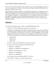
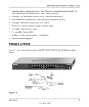
... high, rack-mountable 17-inch chassis. • Fan speed control supported. Package Contents Figure 1-1 shows the package contents of the NETGEAR GS716T and GS724T Series Smart Switch. Reset PWR ® ProSafe 24 Port Gigabit Smart Switch 1 3 5 7 9 11 13 15 17 19 21 23 LINK/ACT SPD Green (1000M) Yellow (100M) FDX 2 4 6 8 10 12 14 16...
... high, rack-mountable 17-inch chassis. • Fan speed control supported. Package Contents Figure 1-1 shows the package contents of the NETGEAR GS716T and GS724T Series Smart Switch. Reset PWR ® ProSafe 24 Port Gigabit Smart Switch 1 3 5 7 9 11 13 15 17 19 21 23 LINK/ACT SPD Green (1000M) Yellow (100M) FDX 2 4 6 8 10 12 14 16...
GS716Tv2/GS724Tv3 Hardware manual
Page 10
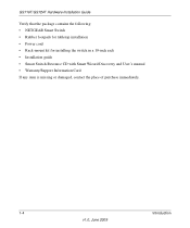
GS716T/GS724T Hardware Installation Guide Verify that the package contains the following: • NETGEAR Smart Switch • Rubber footpads for tabletop installation • Power cord • Rack-mount kit for installing the switch in a 19-inch rack • Installation guide • Smart Switch Resource CD with Smart Wizard Discovery and User's manual • Warranty/Support Information Card If any item is missing or damaged, contact the place of purchase immediately. 1-4 Introduction v1.0, June 2009
GS716T/GS724T Hardware Installation Guide Verify that the package contains the following: • NETGEAR Smart Switch • Rubber footpads for tabletop installation • Power cord • Rack-mount kit for installing the switch in a 19-inch rack • Installation guide • Smart Switch Resource CD with Smart Wizard Discovery and User's manual • Warranty/Support Information Card If any item is missing or damaged, contact the place of purchase immediately. 1-4 Introduction v1.0, June 2009

GS716Tv2/GS724Tv3 Hardware manual
Page 11
...GS724T Front and Back Panel Configuration • LED Designations • Device Hardware Interfaces GS716T Front and Back Panel Configuration The GS716T is capable of sensing the line speed and negotiating the operation duplex mode with the link partner automatically Figure 2-1 illustrates the NETGEAR GS716T Smart Switch front panel: System LEDs Reset PWR ® ProSafe... 16 Port Gigabit Smart Switch 1 3 5 7 9 11 13 15 LINK/ACT SPD ...
...GS724T Front and Back Panel Configuration • LED Designations • Device Hardware Interfaces GS716T Front and Back Panel Configuration The GS716T is capable of sensing the line speed and negotiating the operation duplex mode with the link partner automatically Figure 2-1 illustrates the NETGEAR GS716T Smart Switch front panel: System LEDs Reset PWR ® ProSafe... 16 Port Gigabit Smart Switch 1 3 5 7 9 11 13 15 LINK/ACT SPD ...
GS716Tv2/GS724Tv3 Hardware manual
Page 12
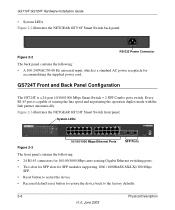
... the line speed and negotiating the operation duplex mode with the link partner automatically Figure 2-3 illustrates the NETGEAR GS724T Smart Switch front panel: System LEDs Reset PWR ® ProSafe 24 Port Gigabit Smart Switch 1 3 5 7 9 11 13 15 17 19 21 23 LINK/ACT SPD Green (1000M) ... Physical Description v1.0, June 2009 GS724T Front and Back Panel Configuration The GS724T is a 24-port 10/100/1000 Mbps Smart Switch + 2 SFP Combo ports switch. GS716T/GS724T Hardware Installation Guide • System LEDs Figure 2-2 illustrates the NETGEAR GS716T Smart Switch back panel: 100-240V ~ ...
... the line speed and negotiating the operation duplex mode with the link partner automatically Figure 2-3 illustrates the NETGEAR GS724T Smart Switch front panel: System LEDs Reset PWR ® ProSafe 24 Port Gigabit Smart Switch 1 3 5 7 9 11 13 15 17 19 21 23 LINK/ACT SPD Green (1000M) ... Physical Description v1.0, June 2009 GS724T Front and Back Panel Configuration The GS724T is a 24-port 10/100/1000 Mbps Smart Switch + 2 SFP Combo ports switch. GS716T/GS724T Hardware Installation Guide • System LEDs Figure 2-2 illustrates the NETGEAR GS716T Smart Switch back panel: 100-240V ~ ...
GS716Tv2/GS724Tv3 Hardware manual
Page 13
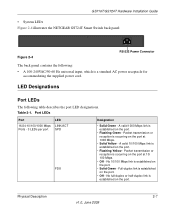
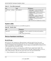
... port. • Flashing Green - Packet transmission or reception is occurring on the port at 1000 Mbps. • Solid Yellow - GS716T/GS724T Hardware Installation Guide • System LEDs Figure 2-4 illustrates the NETGEAR GS724T Smart Switch back panel: Figure 2-4 100-240V ~ 50-60Hz RS-232 Power Connector The back panel contains the following table describes the...
... port. • Flashing Green - Packet transmission or reception is occurring on the port at 1000 Mbps. • Solid Yellow - GS716T/GS724T Hardware Installation Guide • System LEDs Figure 2-4 illustrates the NETGEAR GS724T Smart Switch back panel: Figure 2-4 100-240V ~ 50-60Hz RS-232 Power Connector The back panel contains the following table describes the...
GS716Tv2/GS724Tv3 Hardware manual
Page 14
... straight-through or crossover cables. System LEDs The following table describes the system LED designations. When inserting a cable into the switch's RJ-45 port, the switch automatically: • Senses whether the cable is occurring on the port at 100 Mbps. • Off - When inserting ...or reception is operating normally. • Off - Power is established on the port at 1000 Mbps. • Solid Yellow - GS716T/GS724T Hardware Installation Guide Table 2-1. A valid 100 Mbps SFP module link is disconnected. All ports support only unshielded twisted-pair (UTP) cable ...
... straight-through or crossover cables. System LEDs The following table describes the system LED designations. When inserting a cable into the switch's RJ-45 port, the switch automatically: • Senses whether the cable is occurring on the port at 100 Mbps. • Off - When inserting ...or reception is operating normally. • Off - Power is established on the port at 1000 Mbps. • Solid Yellow - GS716T/GS724T Hardware Installation Guide Table 2-1. A valid 100 Mbps SFP module link is disconnected. All ports support only unshielded twisted-pair (UTP) cable ...
GS716Tv2/GS724Tv3 Hardware manual
Page 15
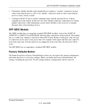
GS716T/GS724T Hardware Installation Guide • Determines whether the link to the attached device requires a "normal" connection (such as when connecting the port to a PC) or an "uplink" connection (such as the AGM731F, AGM732F, or AGM733 from NETGEAR, allowing fiber connections on the network. ...If both copper and fiber port cannot be active at any given time. Factory Defaults Button The Smart Switch has a Factory Default button so that you enable the Factory Default...
GS716T/GS724T Hardware Installation Guide • Determines whether the link to the attached device requires a "normal" connection (such as when connecting the port to a PC) or an "uplink" connection (such as the AGM731F, AGM732F, or AGM733 from NETGEAR, allowing fiber connections on the network. ...If both copper and fiber port cannot be active at any given time. Factory Defaults Button The Smart Switch has a Factory Default button so that you enable the Factory Default...
GS716Tv2/GS724Tv3 Hardware manual
Page 18
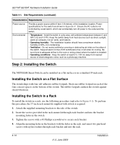
...mounting holes in the brackets with the holes in a dry area, with four self-adhesive rubber footpads. GS716T/GS724T Hardware Installation Guide Table 4-1. Install the switch in the rack, and insert two pan-head screws with nylon washers through each bracket. 4. Insert the ...(and refer to the side of the switch. Step 2: Installing the Switch The NETGEAR Smart Switch can accidentally turn off power to secure each bracket and into the rack. 4-14 v1.0, June 2009 Installation Installing the Switch on a Flat Surface The switch ships with ambient temperature between 0 and...
...mounting holes in the brackets with the holes in a dry area, with four self-adhesive rubber footpads. GS716T/GS724T Hardware Installation Guide Table 4-1. Install the switch in the rack, and insert two pan-head screws with nylon washers through each bracket. 4. Insert the ...(and refer to the side of the switch. Step 2: Installing the Switch The NETGEAR Smart Switch can accidentally turn off power to secure each bracket and into the rack. 4-14 v1.0, June 2009 Installation Installing the Switch on a Flat Surface The switch ships with ambient temperature between 0 and...
GS716Tv2/GS724Tv3 Hardware manual
Page 19
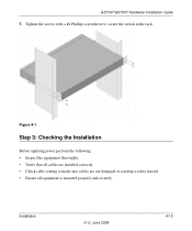
Tighten the screws with a #2 Phillips screwdriver to make sure cables are not damaged or creating a safety hazard. • Ensure all cables are installed correctly. • Check cable routing to secure the switch in the rack. Installation v1.0, June 2009 4-15 GS716T/GS724T Hardware Installation Guide 5. Figure 4-1 Step 3: Checking the Installation Before applying power perform the following: • Inspect the equipment thoroughly. • Verify that all equipment is mounted properly and securely.
Tighten the screws with a #2 Phillips screwdriver to make sure cables are not damaged or creating a safety hazard. • Ensure all cables are installed correctly. • Check cable routing to secure the switch in the rack. Installation v1.0, June 2009 4-15 GS716T/GS724T Hardware Installation Guide 5. Figure 4-1 Step 3: Checking the Installation Before applying power perform the following: • Inspect the equipment thoroughly. • Verify that all equipment is mounted properly and securely.

GS716Tv2/GS724Tv3 Hardware manual
Page 20
... at this time, skip this procedure. Step 5: Installing an SFP GBIC Module The following procedure describes how to connect PCs to the switch's RJ-45 ports. Use Category 5 (Cat5) Unshielded Twisted-Pair (UTP) cable terminated with an RJ-45 connector to an RJ-...To install an SFP GBIC module: 4-16 v1.0, June 2009 Installation GS716T/GS724T Hardware Installation Guide Step 4: Connecting Devices to the Switch The following procedure describes how to 100 m (328 ft.). The NETGEAR Smart Switch contains Auto Uplink™ technology, which allows the attaching of devices using either...
... at this time, skip this procedure. Step 5: Installing an SFP GBIC Module The following procedure describes how to connect PCs to the switch's RJ-45 ports. Use Category 5 (Cat5) Unshielded Twisted-Pair (UTP) cable terminated with an RJ-45 connector to an RJ-...To install an SFP GBIC module: 4-16 v1.0, June 2009 Installation GS716T/GS724T Hardware Installation Guide Step 4: Connecting Devices to the Switch The following procedure describes how to 100 m (328 ft.). The NETGEAR Smart Switch contains Auto Uplink™ technology, which allows the attaching of devices using either...
GS716Tv2/GS724Tv3 Hardware manual
Page 21
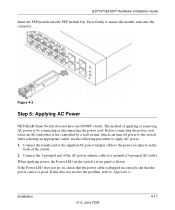
... procedure to Appendix A . If this does not resolve the problem, refer to apply AC power. 1. Connect the 3-pronged end of the switch. 2. Press firmly to a grounded 3-pronged AC outlet. Before connecting the power cord, select an AC outlet that the power source is by a wall... panel is not controlled by connecting or disconnecting the power cord. Figure 4-3 Step 6: Applying AC Power NETGEAR Smart Switch does not have an ON/OFF switch. GS716T/GS724T Hardware Installation Guide Insert the SFP module into the connector. If the Power LED does not go on the back of ...
... procedure to Appendix A . If this does not resolve the problem, refer to apply AC power. 1. Connect the 3-pronged end of the switch. 2. Press firmly to a grounded 3-pronged AC outlet. Before connecting the power cord, select an AC outlet that the power source is by a wall... panel is not controlled by connecting or disconnecting the power cord. Figure 4-3 Step 6: Applying AC Power NETGEAR Smart Switch does not have an ON/OFF switch. GS716T/GS724T Hardware Installation Guide Insert the SFP module into the connector. If the Power LED does not go on the back of ...

GS716Tv2/GS724Tv3 Hardware manual
Page 22
For more information about managing the switch, see the GS716T/GS724T Series Software Administration Manual on the device. After powering up , there is not required for viewing, changing, and monitoring the way it works. The ports ... in the improvement of its overall performance as well as the performance of the network. GS716T/GS724T Hardware Installation Guide Step 7: Managing the Switch using a Web Browser or the PC Utility The NETGEAR Smart Switch contains software for the switch to work. The default IP address is 192.168.0.239 and subnet mask 255.255...
For more information about managing the switch, see the GS716T/GS724T Series Software Administration Manual on the device. After powering up , there is not required for viewing, changing, and monitoring the way it works. The ports ... in the improvement of its overall performance as well as the performance of the network. GS716T/GS724T Hardware Installation Guide Step 7: Managing the Switch using a Web Browser or the PC Utility The NETGEAR Smart Switch contains software for the switch to work. The default IP address is 192.168.0.239 and subnet mask 255.255...


