GS716Tv2/GS724Tv3 Hardware manual
Page 4
GS716T/GS724T Hardware Installation Guide Step 3: Checking the Installation 4-15 Step 4: Connecting Devices to the Switch 4-16 Step 5: Installing an SFP GBIC Module 4-16 Step 6: Applying AC Power 4-17 Step 7: Managing the Switch using a Web Browser or the PC Utility 4-18 Appendix A Troubleshooting Troubleshooting Chart A-19 Additional Troubleshooting Suggestions A-20 Network Adapter Cards A-20 Configuration ...A-20 Switch Integrity ...A-20 Auto-Negotiation A-21 Appendix B Technical Specifications Index iv v1.0, June 2009
GS716T/GS724T Hardware Installation Guide Step 3: Checking the Installation 4-15 Step 4: Connecting Devices to the Switch 4-16 Step 5: Installing an SFP GBIC Module 4-16 Step 6: Applying AC Power 4-17 Step 7: Managing the Switch using a Web Browser or the PC Utility 4-18 Appendix A Troubleshooting Troubleshooting Chart A-19 Additional Troubleshooting Suggestions A-20 Network Adapter Cards A-20 Configuration ...A-20 Switch Integrity ...A-20 Auto-Negotiation A-21 Appendix B Technical Specifications Index iv v1.0, June 2009
GS716Tv2/GS724Tv3 Hardware manual
Page 6
GS716T/GS724T Hardware Installation Guide Danger: This is written for the Smart Switch according to take heed of this notice may result in personal injury or death. • Scope. Failure to these specifications: Product Version Manual Publication Date Smart Switch June 2009 Note: Product updates are available on the NETGEAR, Inc. This manual is a safety warning. website at http://kbserver.netgear.com/main.asp. Revision History Part Number Version Number Date 202-10510-01 1.0 June 2009 Description Initial release vi v1.0, June 2009
GS716T/GS724T Hardware Installation Guide Danger: This is written for the Smart Switch according to take heed of this notice may result in personal injury or death. • Scope. Failure to these specifications: Product Version Manual Publication Date Smart Switch June 2009 Note: Product updates are available on the NETGEAR, Inc. This manual is a safety warning. website at http://kbserver.netgear.com/main.asp. Revision History Part Number Version Number Date 202-10510-01 1.0 June 2009 Description Initial release vi v1.0, June 2009
GS716Tv2/GS724Tv3 Hardware manual
Page 18
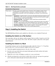
...should have a maximum relative humidity of the switch. 2. Site Requirements (continued) Characteristics Requirements Power source Environmental Provide a power source within 6 feet (1.8 meters) of the switch. Power specifications for cooling. Installing the Switch on the bottom of electromagnetic noise, such...Switch The NETGEAR Smart Switch can accidentally turn off power to the side of 90%, non-condensing. • Ventilation - To perform this procedure, the 17-inch rack-mount kit supplied with ambient temperature between 0 and 55ºC (32 and 131ºF). GS716T/GS724T...
...should have a maximum relative humidity of the switch. 2. Site Requirements (continued) Characteristics Requirements Power source Environmental Provide a power source within 6 feet (1.8 meters) of the switch. Power specifications for cooling. Installing the Switch on the bottom of electromagnetic noise, such...Switch The NETGEAR Smart Switch can accidentally turn off power to the side of 90%, non-condensing. • Ventilation - To perform this procedure, the 17-inch rack-mount kit supplied with ambient temperature between 0 and 55ºC (32 and 131ºF). GS716T/GS724T...

GS716Tv2/GS724Tv3 Hardware manual
Page 20
...: Ethernet specifications limit the cable length between the switch and the attached device to install an SFP Gigabit Ethernet module in the switch's Gigabit module bay. Step 5: Installing an SFP GBIC Module The following procedure describes how to connect PCs to the switch's RJ-... The NETGEAR Smart Switch contains Auto Uplink™ technology, which allows the attaching of devices using either straight-through or crossover cables. Standard SFP GBIC modules are sold separately from the Smart Switch. GS716T/GS724T Hardware Installation Guide Step 4: Connecting Devices to the Switch The ...
...: Ethernet specifications limit the cable length between the switch and the attached device to install an SFP Gigabit Ethernet module in the switch's Gigabit module bay. Step 5: Installing an SFP GBIC Module The following procedure describes how to connect PCs to the switch's RJ-... The NETGEAR Smart Switch contains Auto Uplink™ technology, which allows the attaching of devices using either straight-through or crossover cables. Standard SFP GBIC modules are sold separately from the Smart Switch. GS716T/GS724T Hardware Installation Guide Step 4: Connecting Devices to the Switch The ...
GS716Tv2/GS724Tv3 Hardware manual
Page 27
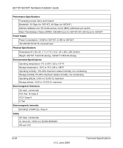
... (MTBF): 465,998 hours for GS716T; 401,205 hours for GS724T Power Supply Power Consumption: 16.5W for GS716T, 21.5W for GS724T 100-240VAC/50-60 Hz universal input Physical Specifications Dimensions (H x W x D): 1.7 x 17.3 x 10.2 / 43 x 440 x 260 (in/mm) Weight: GS716T: 5.64/2.56 (lbs/kg), GS724T: 5.86/2.66 (lbs/kg) Environmental Specifications Operating temperature: 0°C to 55...
... (MTBF): 465,998 hours for GS716T; 401,205 hours for GS724T Power Supply Power Consumption: 16.5W for GS716T, 21.5W for GS724T 100-240VAC/50-60 Hz universal input Physical Specifications Dimensions (H x W x D): 1.7 x 17.3 x 10.2 / 43 x 440 x 260 (in/mm) Weight: GS716T: 5.64/2.56 (lbs/kg), GS724T: 5.86/2.66 (lbs/kg) Environmental Specifications Operating temperature: 0°C to 55...
GS716Tv2/GS724Tv3 Hardware manual
Page 28
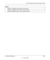
GS716T/GS724T Hardware Installation Guide Modules AGM731F 1000BASE-SX SFP GBIC for multimode fiber AGM732F 1000BASE-LX SFP GBIC for single mode fiber AGM733 1000BASE-LZ GBIC for long haul single mode fiber Technical Specifications v1.0, June 2009 B-25
GS716T/GS724T Hardware Installation Guide Modules AGM731F 1000BASE-SX SFP GBIC for multimode fiber AGM732F 1000BASE-LX SFP GBIC for single mode fiber AGM733 1000BASE-LZ GBIC for long haul single mode fiber Technical Specifications v1.0, June 2009 B-25


