
FS726T User Manual
Page 4
....1Q Tag VLAN 3-7 Switch> Trunking Page 3-9 Switch> Monitor Page 3-10 Switch> Advanced> Jumbo Frame 3-10 Switch> Advanced> Spanning Tree Page 3-11 Switch> Advanced> SNMP 3-11 Firmware Menu ...3-12 Firmware> Configuration Backup Page 3-12 Firmware> Factory Reset Page 3-12 Logout ...3-13 Chapter 5 Software Upgrade Appendix A Default Settings Appendix B IEEE 802.1Q Virtual Local Area Network (VLAN) IEEE 802...
....1Q Tag VLAN 3-7 Switch> Trunking Page 3-9 Switch> Monitor Page 3-10 Switch> Advanced> Jumbo Frame 3-10 Switch> Advanced> Spanning Tree Page 3-11 Switch> Advanced> SNMP 3-11 Firmware Menu ...3-12 Firmware> Configuration Backup Page 3-12 Firmware> Factory Reset Page 3-12 Logout ...3-13 Chapter 5 Software Upgrade Appendix A Default Settings Appendix B IEEE 802.1Q Virtual Local Area Network (VLAN) IEEE 802...
FS726T User Manual
Page 16
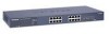
...relevant section of Help Menu System Menu There are below: Browse: Refresh: Apply: Add: Delete: Factory Reset: Help: Locates a certain path for a desired file. If you will go to the Switch> Port Configuration page. • ID: The port number on the system Submits change request to ...refreshes screen data Deletes selected entries from table and refreshes screen data Restore the system factory default value. The possible entries are several buttons that screen's data from current values on the switch • Speed: Indicates the communication mode set for the port. Goes to ...
...relevant section of Help Menu System Menu There are below: Browse: Refresh: Apply: Add: Delete: Factory Reset: Help: Locates a certain path for a desired file. If you will go to the Switch> Port Configuration page. • ID: The port number on the system Submits change request to ...refreshes screen data Deletes selected entries from table and refreshes screen data Restore the system factory default value. The possible entries are several buttons that screen's data from current values on the switch • Speed: Indicates the communication mode set for the port. Goes to ...

FS726T User Manual
Page 27
...file in Figure 5-34. Note: The Backup file does not affect the password and MAC address of the switch Firmware> Factory Reset Page You can always reset the switch to default values by using a duplicate configuration): • Click Restore to a previous configuration. Web-Based Management...browser connection. Firmware Menu Smart Switch Series Software Manual There are 2 options available: • Configuration Backup • Factory Reset Firmware> Configuration Backup Page You can backup the system and switch settings to your PC to the current switch. Additionally, if you want them...
...file in Figure 5-34. Note: The Backup file does not affect the password and MAC address of the switch Firmware> Factory Reset Page You can always reset the switch to default values by using a duplicate configuration): • Click Restore to a previous configuration. Web-Based Management...browser connection. Firmware Menu Smart Switch Series Software Manual There are 2 options available: • Configuration Backup • Factory Reset Firmware> Configuration Backup Page You can backup the system and switch settings to your PC to the current switch. Additionally, if you want them...
FS726T User Manual
Page 45
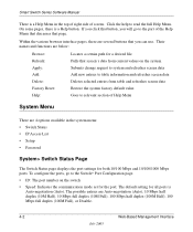
...-negotiation Enabled Enabled DHCP enabled password Port-Based VLAN Disabled Optimized for the NETGEAR Smart Switches. Appendix A Default Settings This appendix provides default settings for flow control, all ports set normal priority Default Settings A-1 July 2005 Table A-1. You can always configure the switch to default settings by using the Factory Reset function from a Web browser.
...-negotiation Enabled Enabled DHCP enabled password Port-Based VLAN Disabled Optimized for the NETGEAR Smart Switches. Appendix A Default Settings This appendix provides default settings for flow control, all ports set normal priority Default Settings A-1 July 2005 Table A-1. You can always configure the switch to default settings by using the Factory Reset function from a Web browser.
GS716Tv2/GS724Tv3 Hardware manual
Page 9
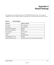
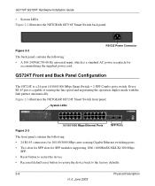
Package Contents Figure 1-1 shows the package contents of the NETGEAR GS716T and GS724T Series Smart Switch. Reset PWR ® ProSafe 24 Port Gigabit Smart Switch 1 3 5 7 9 11 13 15 17 19 21 23 LINK/ACT SPD Green (1000M) Yellow (100M) FDX 2 4 6 8 10 12 14 16 18 20...17 19 21 23T 14 16 18 20 22 24T 23F 24F Link/ Link/ ACT ACT MODEL GS724T Auto™ Uplink Factory Defaults Figure 1-1 Introduction 1-3 v1.0, June 2009 GS716T/GS724T Hardware Installation Guide • Automatic address learning function to minimize packet loss/frame drops. • Half-duplex back-pressure...
Package Contents Figure 1-1 shows the package contents of the NETGEAR GS716T and GS724T Series Smart Switch. Reset PWR ® ProSafe 24 Port Gigabit Smart Switch 1 3 5 7 9 11 13 15 17 19 21 23 LINK/ACT SPD Green (1000M) Yellow (100M) FDX 2 4 6 8 10 12 14 16 18 20...17 19 21 23T 14 16 18 20 22 24T 23F 24F Link/ Link/ ACT ACT MODEL GS724T Auto™ Uplink Factory Defaults Figure 1-1 Introduction 1-3 v1.0, June 2009 GS716T/GS724T Hardware Installation Guide • Automatic address learning function to minimize packet loss/frame drops. • Half-duplex back-pressure...

GS716Tv2/GS724Tv3 Hardware manual
Page 11
...capable of sensing the line speed and negotiating the operation duplex mode with the link partner automatically Figure 2-1 illustrates the NETGEAR GS716T Smart Switch front panel: System LEDs Reset PWR ® ProSafe 16 Port Gigabit Smart Switch 1 3 5 7 9 11 13 15 LINK/ACT SPD Green (1000M) Yellow (100M) FDX 2 4 ...Mbps auto sensing Gigabit Ethernet switching ports. • Two SFP slots for SFP modules supporting 1000 (1000BASE-SX/LX)/100 Mbps SFP. • Reset button to restart the device. • Recessed default reset button to restore the device back to the factory defaults. • Port ...
...capable of sensing the line speed and negotiating the operation duplex mode with the link partner automatically Figure 2-1 illustrates the NETGEAR GS716T Smart Switch front panel: System LEDs Reset PWR ® ProSafe 16 Port Gigabit Smart Switch 1 3 5 7 9 11 13 15 LINK/ACT SPD Green (1000M) Yellow (100M) FDX 2 4 ...Mbps auto sensing Gigabit Ethernet switching ports. • Two SFP slots for SFP modules supporting 1000 (1000BASE-SX/LX)/100 Mbps SFP. • Reset button to restart the device. • Recessed default reset button to restore the device back to the factory defaults. • Port ...
GS716Tv2/GS724Tv3 Hardware manual
Page 12
... line speed and negotiating the operation duplex mode with the link partner automatically Figure 2-3 illustrates the NETGEAR GS724T Smart Switch front panel: System LEDs Reset PWR ® ProSafe 24 Port Gigabit Smart Switch 1 3 5 7 9 11 13 15 17 19 21 23 LINK/ACT SPD Green (1000M.... • Reset button to restart the device. • Recessed default reset button to restore the device back to the factory defaults. 2-6 Physical Description v1.0, June 2009 GS716T/GS724T Hardware Installation Guide • System LEDs Figure 2-2 illustrates the NETGEAR GS716T Smart Switch back panel: 100...
... line speed and negotiating the operation duplex mode with the link partner automatically Figure 2-3 illustrates the NETGEAR GS724T Smart Switch front panel: System LEDs Reset PWR ® ProSafe 24 Port Gigabit Smart Switch 1 3 5 7 9 11 13 15 17 19 21 23 LINK/ACT SPD Green (1000M.... • Reset button to restart the device. • Recessed default reset button to restore the device back to the factory defaults. 2-6 Physical Description v1.0, June 2009 GS716T/GS724T Hardware Installation Guide • System LEDs Figure 2-2 illustrates the NETGEAR GS716T Smart Switch back panel: 100...
GS716Tv2/GS724Tv3 Hardware manual
Page 29
... 100BASE-TX 1-2 10BASE-T 1-2 1U 1-3 8-pin 2-8 A AC Power 2-6, 2-7 AGM731F 2-9 AGM732F 2-9 AGM733 2-9 Applying AC Power 4-17 Attaching Switch to a Rack 4-15 Auto Sensing 1-2 Auto Uplink 2-8, 2-9 Auto-negotiating 1-2 Auto-sensing 2-8 B Back-pressure 1-3 Brackets 4-14 C Category 5...Port 2-9 Combo Ports 1-2 Connecting Devices to the Switch 4-16 Copper 1-1 Crossover 2-8 D Default IP Address 4-18 Default Reset Button 2-5, 2-6 Device Hardware Interfaces 2-8 Duplex Mode 2-8 E Example of Desktop Switching 3-11 F Factory Default Button 2-9 Factory Defaults 2-5 Fiber Connectivity 1-1 Flat Surface 4-14 Full...
... 100BASE-TX 1-2 10BASE-T 1-2 1U 1-3 8-pin 2-8 A AC Power 2-6, 2-7 AGM731F 2-9 AGM732F 2-9 AGM733 2-9 Applying AC Power 4-17 Attaching Switch to a Rack 4-15 Auto Sensing 1-2 Auto Uplink 2-8, 2-9 Auto-negotiating 1-2 Auto-sensing 2-8 B Back-pressure 1-3 Brackets 4-14 C Category 5...Port 2-9 Combo Ports 1-2 Connecting Devices to the Switch 4-16 Copper 1-1 Crossover 2-8 D Default IP Address 4-18 Default Reset Button 2-5, 2-6 Device Hardware Interfaces 2-8 Duplex Mode 2-8 E Example of Desktop Switching 3-11 F Factory Default Button 2-9 Factory Defaults 2-5 Fiber Connectivity 1-1 Flat Surface 4-14 Full...
GS716T Hardware manual
Page 3
... Back Panels ...9 10/100/1000 Mbps RJ-45 Ports ...9 SFP GBIC Module ...10 LED Descriptions ...10 Reset Button ...10 Factory Defaults Button ...11 CHAPTER 3: APPLICATIONS...12 Desktop Switching ...12 Backbone Switching ...13 CHAPTER 4: INSTALLATION...14 Step 1: Preparing the Site ...14 Step 2: Installing the Switch ...14 Step 3: Checking the Installation...15 Step 4: Connecting Devices to the...
... Back Panels ...9 10/100/1000 Mbps RJ-45 Ports ...9 SFP GBIC Module ...10 LED Descriptions ...10 Reset Button ...10 Factory Defaults Button ...11 CHAPTER 3: APPLICATIONS...12 Desktop Switching ...12 Backbone Switching ...13 CHAPTER 4: INSTALLATION...14 Step 1: Preparing the Site ...14 Step 2: Installing the Switch ...14 Step 3: Checking the Installation...15 Step 4: Connecting Devices to the...

GS716T Hardware manual
Page 4
FRONT PANEL OF THE GS716T GIGABIT SMART SWITCH ...9 FIGURE 2-2. ATTACHING MOUNTING BRACKETS...15 FIGURE 4-2. EXAMPLE OF DESKTOP SWITCHING...12 FIGURE 3-2. FACTORY DEFAULTS BUTTON OF THE GS716T GIGABIT SMART SWITCH 11 FIGURE 3-1. CONNECTING DEVICES TO THE SWITCH ...15 FIGURE 4-3. RESET BUTTON OF THE GS716T GIGABIT SMART SWITCH ...10 FIGURE 2-4. BACK PANEL OF THE GS716T GIGABIT SMART SWITCH ...9 FIGURE 2-3. EXAMPLE OF BACKBONE SWITCHING ...13 FIGURE 4-1. Figures FIGURE 1-1. PACKAGE CONTENTS ...8 FIGURE 2-1. INSTALLING A SFP GBIC MODULE INTO GS716T ...16 Page 4 of 20
FRONT PANEL OF THE GS716T GIGABIT SMART SWITCH ...9 FIGURE 2-2. ATTACHING MOUNTING BRACKETS...15 FIGURE 4-2. EXAMPLE OF DESKTOP SWITCHING...12 FIGURE 3-2. FACTORY DEFAULTS BUTTON OF THE GS716T GIGABIT SMART SWITCH 11 FIGURE 3-1. CONNECTING DEVICES TO THE SWITCH ...15 FIGURE 4-3. RESET BUTTON OF THE GS716T GIGABIT SMART SWITCH ...10 FIGURE 2-4. BACK PANEL OF THE GS716T GIGABIT SMART SWITCH ...9 FIGURE 2-3. EXAMPLE OF BACKBONE SWITCHING ...13 FIGURE 4-1. Figures FIGURE 1-1. PACKAGE CONTENTS ...8 FIGURE 2-1. INSTALLING A SFP GBIC MODULE INTO GS716T ...16 Page 4 of 20
GS716T Hardware manual
Page 7
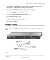
... the NETGEAR ProSafe GS716T Gigabit Smart Switch. • Sixteen 10/100/1000 Mbps auto-sensing Gigabit Ethernet switching ports • Two SFP GBIC combo Gigabit Ethernet slots for optional fiber connectivity • Reset Button • Factory Defaults Button • Administrative switch management ...device follow control ♦ Support Auto-Discovery application program for discovering and managing the smart switches on the network ♦ Support flash upgrading, configuration backup/restore and factory reset • Full compatibility with IEEE standards: o IEEE 802.3i (10BASE-T) o IEEE...
... the NETGEAR ProSafe GS716T Gigabit Smart Switch. • Sixteen 10/100/1000 Mbps auto-sensing Gigabit Ethernet switching ports • Two SFP GBIC combo Gigabit Ethernet slots for optional fiber connectivity • Reset Button • Factory Defaults Button • Administrative switch management ...device follow control ♦ Support Auto-Discovery application program for discovering and managing the smart switches on the network ♦ Support flash upgrading, configuration backup/restore and factory reset • Full compatibility with IEEE standards: o IEEE 802.3i (10BASE-T) o IEEE...
GS716T Hardware manual
Page 9
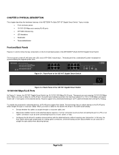
... crossover cables. Page 9 of the NETGEAR ProSafe GS716T Gigabit Smart Switch. Topics include: • Front and back panels • 10/100/1000 Mbps auto-sensing RJ-45 ports • SFP GBIC Module bay • LED descriptions • Reset button • Factory defaults button Front and Back Panels Figures... ports support only unshielded twisted-pair (UTP) cable terminated with an 8-pin RJ-45 plug. Back Panel of the NETGEAR ProSafe GS716T Gigabit Smart Switch. Front Panel of the attached device. The back panel has a standard AC power receptacle for attaching devices, all RJ...
... crossover cables. Page 9 of the NETGEAR ProSafe GS716T Gigabit Smart Switch. Topics include: • Front and back panels • 10/100/1000 Mbps auto-sensing RJ-45 ports • SFP GBIC Module bay • LED descriptions • Reset button • Factory defaults button Front and Back Panels Figures... ports support only unshielded twisted-pair (UTP) cable terminated with an 8-pin RJ-45 plug. Back Panel of the NETGEAR ProSafe GS716T Gigabit Smart Switch. Front Panel of the attached device. The back panel has a standard AC power receptacle for attaching devices, all RJ...


