EN516 Installation Guide
Page 2
... make changes to change without notice. Das vorschriftsmäßige Betreiben einiger Geräte (z.B. Information is operated in accordance with the instruction manual, it may occur due to radio communications. Statement of Conditions In the interest of NETGEAR, Inc. Bestätigung des Herstellers/Importeurs Es wird hiermit bestätigt, daß das NETGEAR Model EN516 Ethernet Hub...
... make changes to change without notice. Das vorschriftsmäßige Betreiben einiger Geräte (z.B. Information is operated in accordance with the instruction manual, it may occur due to radio communications. Statement of Conditions In the interest of NETGEAR, Inc. Bestätigung des Herstellers/Importeurs Es wird hiermit bestätigt, daß das NETGEAR Model EN516 Ethernet Hub...
EN516 Installation Guide
Page 3
... access at the universal resource locator (URL) http:// www.NETGEAR.com. To contact customer support or to certain restrictions. Compliance with post-installation questions or problems, contact your NETGEAR system or with the applicable regulations is dependent upon the use of shielded cables. The operation of purchase representative. Consequently, when this document and publications for compliance with the regulations. Please refer...
... access at the universal resource locator (URL) http:// www.NETGEAR.com. To contact customer support or to certain restrictions. Compliance with post-installation questions or problems, contact your NETGEAR system or with the applicable regulations is dependent upon the use of shielded cables. The operation of purchase representative. Consequently, when this document and publications for compliance with the regulations. Please refer...
EN516 Installation Guide
Page 7
... the Model EN516 hub 2-4 Figure 3-1. Figure 3-4. Figure 3-6. Straight-through the AUI port 3-9 Connecting multiple NETGEAR products 3-10 Figure B-1. Figure 3-3. Figure 3-7. Figure C-3. Crossover twisted pair cable B-2 Figure C-1. Figure C-2. Rear panel of the Model EN516 hub 2-1 Figure 2-2. Figure C-4. Figures Figure 2-1. Figure 3-2. Installing mounting brackets to the hub and to a rack 3-4 Connecting a workstation to an RJ-45 port on the Model EN516 hub .....3-5 Cascading multiple hubs in a hierarchical star through the RJ-45 ports ..3-6 Cascading multiple hubs daisy...
... the Model EN516 hub 2-4 Figure 3-1. Figure 3-4. Figure 3-6. Straight-through the AUI port 3-9 Connecting multiple NETGEAR products 3-10 Figure B-1. Figure 3-3. Figure 3-7. Figure C-3. Crossover twisted pair cable B-2 Figure C-1. Figure C-2. Rear panel of the Model EN516 hub 2-1 Figure 2-2. Figure C-4. Figures Figure 2-1. Figure 3-2. Installing mounting brackets to the hub and to a rack 3-4 Connecting a workstation to an RJ-45 port on the Model EN516 hub .....3-5 Cascading multiple hubs in a hierarchical star through the RJ-45 ports ..3-6 Cascading multiple hubs daisy...
EN516 Installation Guide
Page 11
... Model EN516 hub offers all the features of the NETGEAR™ Model EN516 Ethernet Hub. These features include: • Sixteen IEEE 802.3-compliant 10BASE-T ports, providing effective information exchange, resource sharing, and a client/server or peer-to-peer applications solution with simple unshielded twisted pair (UTP) wiring • Attachment unit interface (AUI) or coaxial BNC backbone support for connecting to install and use the hub and...
... Model EN516 hub offers all the features of the NETGEAR™ Model EN516 Ethernet Hub. These features include: • Sixteen IEEE 802.3-compliant 10BASE-T ports, providing effective information exchange, resource sharing, and a client/server or peer-to-peer applications solution with simple unshielded twisted pair (UTP) wiring • Attachment unit interface (AUI) or coaxial BNC backbone support for connecting to install and use the hub and...
EN516 Installation Guide
Page 12
Installation Guide for the Model EN516 Ethernet Hub • Built-in 100-240 V switching power supply, eliminating the need for bulky wall transformers • Thirty-eight front panel light emitting diode (LED) indicators, providing real-time status of the individual ports and overall hub status • Plug-and-play with no software to configure • Hub functions such as packet retiming, collision detection, preamble regeneration, and fragment extension...
Installation Guide for the Model EN516 Ethernet Hub • Built-in 100-240 V switching power supply, eliminating the need for bulky wall transformers • Thirty-eight front panel light emitting diode (LED) indicators, providing real-time status of the individual ports and overall hub status • Plug-and-play with no software to configure • Hub functions such as packet retiming, collision detection, preamble regeneration, and fragment extension...
EN516 Installation Guide
Page 13
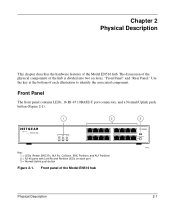
... the hardware features of the Model EN516 hub 3 MODELEN516 8 Normal/Uplink 16 7432 Physical Description 2-1 Use the key at the bottom of the hub is divided into two sections, "Front Panel" and "Rear Panel." Front Panel The front panel contains LEDs, 16 RJ-45 10BASE-T port connectors, and a Normal/Uplink push button (Figure 2-1). 1 2 16 PORT 10BASE-T Ethernet Hub BNC AUI Power Rx Rx Collision Partition Partition 1 Link...
... the hardware features of the Model EN516 hub 3 MODELEN516 8 Normal/Uplink 16 7432 Physical Description 2-1 Use the key at the bottom of the hub is divided into two sections, "Front Panel" and "Rear Panel." Front Panel The front panel contains LEDs, 16 RJ-45 10BASE-T port connectors, and a Normal/Uplink push button (Figure 2-1). 1 2 16 PORT 10BASE-T Ethernet Hub BNC AUI Power Rx Rx Collision Partition Partition 1 Link...
EN516 Installation Guide
Page 15
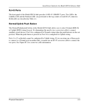
... cable information. Ports 1 to 15 on the Model EN516 hub allows you to select Normal (MDI-X) or Uplink (MDI) wiring for the Model EN516 Ethernet Hub RJ-45 Ports The front panel of the Model EN516 hub provides 16 RJ-45 10BASE-T ports. If you must use a crossover cable to a Normal port in Table 2-1. Installation Guide for port 16, eliminating the need to use an RJ-45 crossover cable to connect the two ports. Two LEDs, the Link...
... cable information. Ports 1 to 15 on the Model EN516 hub allows you to select Normal (MDI-X) or Uplink (MDI) wiring for the Model EN516 Ethernet Hub RJ-45 Ports The front panel of the Model EN516 hub provides 16 RJ-45 10BASE-T ports. If you must use a crossover cable to a Normal port in Table 2-1. Installation Guide for port 16, eliminating the need to use an RJ-45 crossover cable to connect the two ports. Two LEDs, the Link...
EN516 Installation Guide
Page 16
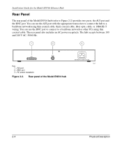
... Key: 1 = AUI port 2 = BNC port 3 = AC power receptacle Figure 2-2. You can use the BNC port to connect to Figure 2-2) provides two ports, the AUI port and the BNC port. Rear panel of the Model EN516 hub (refer to a backbone network or other PCs using thin coaxial cable, thick coaxial cable, fiber optic cable, or 10BASE-T wiring. You can use the AUI port with the appropriate transceiver to connect the hub to a backbone network using...
... Key: 1 = AUI port 2 = BNC port 3 = AC power receptacle Figure 2-2. You can use the BNC port to connect to Figure 2-2) provides two ports, the AUI port and the BNC port. Rear panel of the Model EN516 hub (refer to a backbone network or other PCs using thin coaxial cable, thick coaxial cable, fiber optic cable, or 10BASE-T wiring. You can use the AUI port with the appropriate transceiver to connect the hub to a backbone network using...
EN516 Installation Guide
Page 18
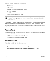
... the Owner Registration Card and return it for product updates and product warranty registration. Installation Guide for the Model EN516 Ethernet Hub • AC power cord • Rack mount kit • Four rubber pads for installing the hub on a flat surface or in a rack, you do not need any wrong, missing, or damaged parts. Keep the carton, including the original packing materials. However...
... the Owner Registration Card and return it for product updates and product warranty registration. Installation Guide for the Model EN516 Ethernet Hub • AC power cord • Rack mount kit • Four rubber pads for installing the hub on a flat surface or in a rack, you do not need any wrong, missing, or damaged parts. Keep the carton, including the original packing materials. However...
EN516 Installation Guide
Page 20
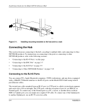
... ports on the Model EN516 hub using twisted pair Ethernet cables. Power Data Collision 1 Link RX 9 Link RX 8 Normal/Uplink 16 Figure 3-1. 7171 Installing mounting brackets to the hub and to a rack Connecting the Hub This section discusses connecting to the hub, cascading to multiple hubs, and connecting to other NETGEAR products, refer to the following sections: • "Connecting to the RJ-45 Ports" on this page • "Connecting to the BNC Port" on page 3-7 • "Connecting to the AUI Port...
... ports on the Model EN516 hub using twisted pair Ethernet cables. Power Data Collision 1 Link RX 9 Link RX 8 Normal/Uplink 16 Figure 3-1. 7171 Installing mounting brackets to the hub and to a rack Connecting the Hub This section discusses connecting to the hub, cascading to multiple hubs, and connecting to other NETGEAR products, refer to the following sections: • "Connecting to the RJ-45 Ports" on this page • "Connecting to the BNC Port" on page 3-7 • "Connecting to the AUI Port...
EN516 Installation Guide
Page 21
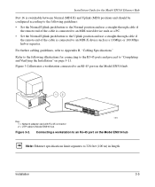
... Uplink position and use a straight-through cable if the remote end of the cable is connected to an MDI-X device such as a 10 Mbps or 100 Mbps hub or repeater. Connecting a workstation to an RJ-45 port on page 3-11. For further cabling guidelines, refer to 328 feet (100 m) in length. Installation Guide for connecting to the RJ-45 ports and proceed to Model EN516 hub Power Data Collision 1 Link RX 9 Link...
... Uplink position and use a straight-through cable if the remote end of the cable is connected to an MDI-X device such as a 10 Mbps or 100 Mbps hub or repeater. Connecting a workstation to an RJ-45 port on page 3-11. For further cabling guidelines, refer to 328 feet (100 m) in length. Installation Guide for connecting to the RJ-45 ports and proceed to Model EN516 hub Power Data Collision 1 Link RX 9 Link...
EN516 Installation Guide
Page 22
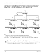
.../Uplink push button set to cascade hubs together. Cascading multiple hubs in Figure 3-3. For example, when PC "A" communicates with the Normal/Uplink push button set to Normal position 2 through 7 = Model EN516 hub with PC "B," the communication path goes from hub 5 to hub 7, passing through the RJ-45 ports Note: Ethernet specifications limit the number of users supported on the network. The RJ-45, BNC, or AUI ports can be used to Uplink...
.../Uplink push button set to cascade hubs together. Cascading multiple hubs in Figure 3-3. For example, when PC "A" communicates with the Normal/Uplink push button set to Normal position 2 through 7 = Model EN516 hub with PC "B," the communication path goes from hub 5 to hub 7, passing through the RJ-45 ports Note: Ethernet specifications limit the number of users supported on the network. The RJ-45, BNC, or AUI ports can be used to Uplink...
EN516 Installation Guide
Page 23
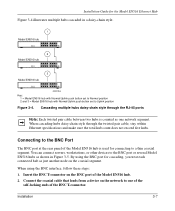
... port of the BNC T-connector. Installation 3-7 By using the BNC interface, follow these steps: 1. Connect the coaxial cable that leads from a device on the network to Uplink position Figure 3-4. When using the BNC port for cascading, you treat each connected hub as shown in a daisy-chain style. 1 Model EN516 hub 2 Model EN516 hub 3 Model EN516 hub 000029EA Key: 1 = Model EN516 hub with Normal/Uplink push button set to Normal position 2 and 3 = Model EN516 hub with Normal/Uplink push button set to one network segment. Cascading multiple hubs...
... port of the BNC T-connector. Installation 3-7 By using the BNC interface, follow these steps: 1. Connect the coaxial cable that leads from a device on the network to Uplink position Figure 3-4. When using the BNC port for cascading, you treat each connected hub as shown in a daisy-chain style. 1 Model EN516 hub 2 Model EN516 hub 3 Model EN516 hub 000029EA Key: 1 = Model EN516 hub with Normal/Uplink push button set to Normal position 2 and 3 = Model EN516 hub with Normal/Uplink push button set to one network segment. Cascading multiple hubs...
EN516 Installation Guide
Page 25
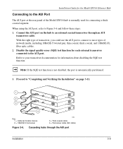
... hubs through an AUI transceiver cable. Disable the signal quality error (SQE) test function for information about disabling the SQE test function. Refer to your transceiver documentation for each external transceiver connected to the AUI port. Connect the AUI port on the hub to "Completing and Verifying the Installation" on page 3-11. 1 2 3 4 Key: 1 = Cable termination device 2 = 10BASE-5 transceiver 31EA 3 = Thick coaxial cable 4 = Transceiver cable (AUI cable) Figure 3-6. Installation Guide for the Model EN516 Ethernet Hub Connecting...
... hubs through an AUI transceiver cable. Disable the signal quality error (SQE) test function for information about disabling the SQE test function. Refer to your transceiver documentation for each external transceiver connected to the AUI port. Connect the AUI port on the hub to "Completing and Verifying the Installation" on page 3-11. 1 2 3 4 Key: 1 = Cable termination device 2 = 10BASE-5 transceiver 31EA 3 = Thick coaxial cable 4 = Transceiver cable (AUI cable) Figure 3-6. Installation Guide for the Model EN516 Ethernet Hub Connecting...
EN516 Installation Guide
Page 26
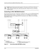
... 56 Model FE516 hub Model SW507 switch Model EN516 hub Model EN516 hub Model EN516 hub Key: 1 = Workstations 2 = 100 Mbps connection 3 = NETGEAR Model FE516 Fast 7228 4 = Server 5 = NETGEAR Model SW507 Ethernet switch 6 = 10 Mbps connection Ethernet hub Figure 3-7. Connecting multiple NETGEAR products 3-10 Installation Figure 3-7 illustrates power users on a 100 Mbps network using the NETGEAR Model FE516 Fast Ethernet Hub and connecting to an Ethernet switch, such as the NETGEAR Model SW507 Ethernet Switch. Installation Guide for the Model EN516 Ethernet Hub Note: Ethernet speci...
... 56 Model FE516 hub Model SW507 switch Model EN516 hub Model EN516 hub Model EN516 hub Key: 1 = Workstations 2 = 100 Mbps connection 3 = NETGEAR Model FE516 Fast 7228 4 = Server 5 = NETGEAR Model SW507 Ethernet switch 6 = 10 Mbps connection Ethernet hub Figure 3-7. Connecting multiple NETGEAR products 3-10 Installation Figure 3-7 illustrates power users on a 100 Mbps network using the NETGEAR Model FE516 Fast Ethernet Hub and connecting to an Ethernet switch, such as the NETGEAR Model SW507 Ethernet Switch. Installation Guide for the Model EN516 Ethernet Hub Note: Ethernet speci...
EN516 Installation Guide
Page 27
Installation Guide for the Model EN516 Ethernet Hub Completing and Verifying the Installation To complete the installation, connect the power cord first to the power entry receptacle on the hub rear panel and then to the hub, the following conditions should exist: • Green Power LED on the front panel is on. • Yellow BNC Partition LED is on if the BNC port is not connected. • Green Link/Rx LED on...
Installation Guide for the Model EN516 Ethernet Hub Completing and Verifying the Installation To complete the installation, connect the power cord first to the power entry receptacle on the hub rear panel and then to the hub, the following conditions should exist: • Green Power LED on the front panel is on. • Yellow BNC Partition LED is on if the BNC port is not connected. • Green Link/Rx LED on...
EN516 Installation Guide
Page 32
... problems occur after altering the network configuration, restore the original connections and determine the problem by resetting it. Turn off the power to the switch and then turn the power to the switch back on. Installation Guide for the phone number of Customer Support in working condition. Ensure that cable distances, repeater limits, and other physical aspects of the hub by implementing the new changes, one procedure at a time...
... problems occur after altering the network configuration, restore the original connections and determine the problem by resetting it. Turn off the power to the switch and then turn the power to the switch back on. Installation Guide for the phone number of Customer Support in working condition. Ensure that cable distances, repeater limits, and other physical aspects of the hub by implementing the new changes, one procedure at a time...
EN516 Installation Guide
Page 37
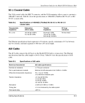
Table B-2 lists the specifications of 10BASE2 (ThinNet) RG 58 A/U or RG 58 C/U coaxial cable Characteristic impedance 50 +/-2 Ω Attenuation (185 m cable) Table B-2. Specifications of 10BASE2 (ThinNet) RG 58 A/U or RG 58 C/U coaxial cable. Installation Guide for the Model EN516 Ethernet Hub 50 Ω Coaxial Cable The 50 Ω coaxial cable, the BNC T-connector, and the 50 Ω terminator, allow a user to construct a 10BASE-2 network.
Table B-2 lists the specifications of 10BASE2 (ThinNet) RG 58 A/U or RG 58 C/U coaxial cable Characteristic impedance 50 +/-2 Ω Attenuation (185 m cable) Table B-2. Specifications of 10BASE2 (ThinNet) RG 58 A/U or RG 58 C/U coaxial cable. Installation Guide for the Model EN516 Ethernet Hub 50 Ω Coaxial Cable The 50 Ω coaxial cable, the BNC T-connector, and the 50 Ω terminator, allow a user to construct a 10BASE-2 network.
EN516 Installation Guide
Page 44
... Model EN516 Ethernet Hub connector AUI pin assignments (table) C-2 BNC C-3 BNC-T C-4 RJ-45 pin assignments (table) C-1 crossover twisted pair cable B-2 customer support iii D daisy-chain cascade 3-7 F FCC statement ii features 1-1 front panel 2-1 H hierarchical star cascade 3-6 I installation cascading ports 3-4 to 3-9 completing 3-11 connecting ports 3-4 to 3-9 connecting to NETGEAR products 3-10 daisy-chain style 3-7 in a rack 3-3 network interface cards 4-4 on a flat surface 3-3 package contents 3-1 tools required 3-2 troubleshooting 4-3 verifying 3-11, 4-4 L LEDs...
... Model EN516 Ethernet Hub connector AUI pin assignments (table) C-2 BNC C-3 BNC-T C-4 RJ-45 pin assignments (table) C-1 crossover twisted pair cable B-2 customer support iii D daisy-chain cascade 3-7 F FCC statement ii features 1-1 front panel 2-1 H hierarchical star cascade 3-6 I installation cascading ports 3-4 to 3-9 completing 3-11 connecting ports 3-4 to 3-9 connecting to NETGEAR products 3-10 daisy-chain style 3-7 in a rack 3-3 network interface cards 4-4 on a flat surface 3-3 package contents 3-1 tools required 3-2 troubleshooting 4-3 verifying 3-11, 4-4 L LEDs...
EN516 Installation Guide
Page 45
... cable specifications (table) B-3 RG 58 C/U coaxial cable B-3 RJ-45 connector pin assignments (table) C-1 RJ-45 Link/Rx LED 2-2, 3-11, 4-2 RJ-45 Partition LED 2-2 RJ-45 ports cascading hubs through 3-4 configuring port 16 3-5 connecting Apple Macintosh computers 3-4 connecting PCs 3-4 connecting UNIX workstations 3-4 description 2-3 using crossover cable 3-4 using transceivers to connect AUI 3-9 Power LED 2-2, 3-11, 4-1 T technical specifications A-1 technical support iii troubleshooting cable 4-3 configuration 4-4 installation 4-3, 4-4 LEDs 4-1 network interface...
... cable specifications (table) B-3 RG 58 C/U coaxial cable B-3 RJ-45 connector pin assignments (table) C-1 RJ-45 Link/Rx LED 2-2, 3-11, 4-2 RJ-45 Partition LED 2-2 RJ-45 ports cascading hubs through 3-4 configuring port 16 3-5 connecting Apple Macintosh computers 3-4 connecting PCs 3-4 connecting UNIX workstations 3-4 description 2-3 using crossover cable 3-4 using transceivers to connect AUI 3-9 Power LED 2-2, 3-11, 4-1 T technical specifications A-1 technical support iii troubleshooting cable 4-3 configuration 4-4 installation 4-3, 4-4 LEDs 4-1 network interface...


