User Guide
Page 2
We take every care in the United States and/or other information: http://www.msi.com.tw/program/service/faq/ faq/esc_faq_list.php Contact our technical staff at: http://support.msi.com.tw/ ii Intel® and Pentium® are registered trademarks of International Business...trademarks of NVIDIA Corporation in the preparation of this document is a registered trademark of Phoenix Technologies Ltd. Visit the MSI website for FAQ, technical guide, BIOS updates, driver updates, and other countries. Alternatively, please try the following help resources for PCB 1.0 Date March ...
We take every care in the United States and/or other information: http://www.msi.com.tw/program/service/faq/ faq/esc_faq_list.php Contact our technical staff at: http://support.msi.com.tw/ ii Intel® and Pentium® are registered trademarks of International Business...trademarks of NVIDIA Corporation in the preparation of this document is a registered trademark of Phoenix Technologies Ltd. Visit the MSI website for FAQ, technical guide, BIOS updates, driver updates, and other countries. Alternatively, please try the following help resources for PCB 1.0 Date March ...
User Guide
Page 8
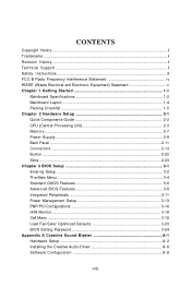
... 2-1 Quick Components Guide 2-2 CPU (Central Processing Unit 2-3 Memory ...2-7 Power Supply ...2-9 Back Panel ...2-11 Connectors ...2-13 Button ...2-22 Slots ...2-23 Chapter 3 BIOS Setup 3-1 Entering Setup ...3-2 The Main Menu ...3-4 Standard CMOS Features 3-6 Advanced BIOS Features 3-8 Integrated Peripherals 3-11 Power Management Setup 3-13 PNP/PCI Configurations 3-16 H/W Monitor ...3-18 Cell Menu ...3-19 Load Fail-Safe...
... 2-1 Quick Components Guide 2-2 CPU (Central Processing Unit 2-3 Memory ...2-7 Power Supply ...2-9 Back Panel ...2-11 Connectors ...2-13 Button ...2-22 Slots ...2-23 Chapter 3 BIOS Setup 3-1 Entering Setup ...3-2 The Main Menu ...3-4 Standard CMOS Features 3-6 Advanced BIOS Features 3-8 Integrated Peripherals 3-11 Power Management Setup 3-13 PNP/PCI Configurations 3-16 H/W Monitor ...3-18 Cell Menu ...3-19 Load Fail-Safe...
User Guide
Page 20
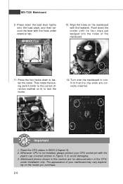
... 9. Press down the cooler until its four clips get wedged into the holes of your CPU socket pin with the heatsink. Mainboard photos shown in BIOS (Chapter 3). 2.
... 9. Press down the cooler until its four clips get wedged into the holes of your CPU socket pin with the heatsink. Mainboard photos shown in BIOS (Chapter 3). 2.

User Guide
Page 30
... recommended CPU fans at processor's official website or consult the vendors for CPUFAN1. Fan/heatsink with +12V. To clear the warning, you must enter the BIOS utility and clear the record. 2 GND 1 CINTRU JCI1 2-16 GND +12V SENSOR Control GND +12V NC CPUFAN1 Sensor +12V GND NBFAN1 GND +12V NC SYSFAN1...
... recommended CPU fans at processor's official website or consult the vendors for CPUFAN1. Fan/heatsink with +12V. To clear the warning, you must enter the BIOS utility and clear the record. 2 GND 1 CINTRU JCI1 2-16 GND +12V SENSOR Control GND +12V NC CPUFAN1 Sensor +12V GND NBFAN1 GND +12V NC SYSFAN1...
User Guide
Page 35
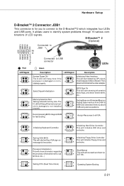
...ule is damaged or not in- 3 stalled properly. Then, detect and initializethe video adapter. 1 2 EarlyChipset Initialization 3 4 BIOS Sign On 1 2 This will start detecting CPU clock, 4 checking type ofvideo onboard. Memory Detection Test Testing Base and Extended ... 2 Initializing Keyboard Controller. 1 2 Initializing Hard Drive Controller This will initialize IDE drive and 3 4 3 4 controller. 1 2 Testing VGA BIOS 1 2 Initializing Floppy Drive Controller This will start showing information 3 4 about logo, processor brand name, etc... It allows users to the D-Bracket...
...ule is damaged or not in- 3 stalled properly. Then, detect and initializethe video adapter. 1 2 EarlyChipset Initialization 3 4 BIOS Sign On 1 2 This will start detecting CPU clock, 4 checking type ofvideo onboard. Memory Detection Test Testing Base and Extended ... 2 Initializing Keyboard Controller. 1 2 Initializing Hard Drive Controller This will initialize IDE drive and 3 4 3 4 controller. 1 2 Testing VGA BIOS 1 2 Initializing Floppy Drive Controller This will start showing information 3 4 about logo, processor brand name, etc... It allows users to the D-Bracket...
User Guide
Page 37
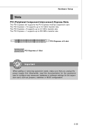
... power supply first. The PCI Express x 1 supports up to 4.0 GB/s transfer rate. Meanwhile, read the documentation for the expansion card, such as jumpers, switches or BIOS configuration. 2-23
... power supply first. The PCI Express x 1 supports up to 4.0 GB/s transfer rate. Meanwhile, read the documentation for the expansion card, such as jumpers, switches or BIOS configuration. 2-23
User Guide
Page 41
Chapter 3 BIOS Setup BIOS Setup This chapter provides information on the screen during the system booting up, and requests you to change the default settings for optimum use. You may need to run the Setup program when: ² An error message appears on the BIOS Setup program and allows you to run SETUP. ² You want to configure the system for customized features. 3-1
Chapter 3 BIOS Setup BIOS Setup This chapter provides information on the screen during the system booting up, and requests you to change the default settings for optimum use. You may need to run the Setup program when: ² An error message appears on the BIOS Setup program and allows you to run SETUP. ² You want to configure the system for customized features. 3-1
User Guide
Page 42
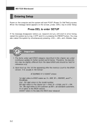
...to the chipset as MS = all standard customers. Upon boot-up, the 1st line appearing after the memory count is usually in this BIOS was released. 3-2 It is the BIOS version. W hen the message below appears on the computer and the system will start POST (Power On Self Test) process. V1.0 ...refers to the BIOS version. 033007 refers to enter Setup. Press DEL to enter SETUP If the message disappears before you respond and you still wish to the customer...
...to the chipset as MS = all standard customers. Upon boot-up, the 1st line appearing after the memory count is usually in this BIOS was released. 3-2 It is the BIOS version. W hen the message below appears on the computer and the system will start POST (Power On Self Test) process. V1.0 ...refers to the BIOS version. 033007 refers to enter Setup. Press DEL to enter SETUP If the message disappears before you respond and you still wish to the customer...
User Guide
Page 43
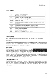
... The on-line description of the highlighted setup function is the Main Menu. A sub-menu contains additional options for the highlighted item. General Help The BIOS setup program provides a General Help screen. Main Menu The main menu lists the setup functions you will see is displayed at the bottom of the... screen. You can call up this field. BIOS Setup Control Keys Enter> Move to the previous item Move to the next item Move to the item in the left of certain fields that...
... The on-line description of the highlighted setup function is the Main Menu. A sub-menu contains additional options for the highlighted item. General Help The BIOS setup program provides a General Help screen. Main Menu The main menu lists the setup functions you will see is displayed at the bottom of the... screen. You can call up this field. BIOS Setup Control Keys Enter> Move to the previous item Move to the next item Move to the item in the left of certain fields that...
User Guide
Page 44
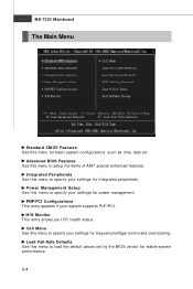
... to specify your settings for frequency/voltage control and overclocking. Load Fail-Safe Defaults Use this menu to load the default values set by the BIOS vendor for basic system configurations, such as time, date etc. H/W Monitor This entry shows your system supports PnP/PCI. Power Management Setup Use this menu... to specify your settings for power management. PNP/PCI Configurations This entry appears if your PC health status. Advanced BIOS Features Use this menu to setup the items of AMI® special enhanced features.
... to specify your settings for frequency/voltage control and overclocking. Load Fail-Safe Defaults Use this menu to load the default values set by the BIOS vendor for basic system configurations, such as time, date etc. H/W Monitor This entry shows your system supports PnP/PCI. Power Management Setup Use this menu... to specify your settings for power management. PNP/PCI Configurations This entry appears if your PC health status. Advanced BIOS Features Use this menu to setup the items of AMI® special enhanced features.
User Guide
Page 45
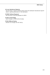
Exit Without Saving Abandon all changes and exit setup. 3-5 Save & Exit Setup Save changes to CMOS and exit setup. BIOS Setting Password Use this menu to load the default values set the password for optimal performance of the mainboard. BIOS Setup Load Optimized Defaults Use this menu to set by the mainboard manufacturer specifically for BIOS.
Exit Without Saving Abandon all changes and exit setup. 3-5 Save & Exit Setup Save changes to CMOS and exit setup. BIOS Setting Password Use this menu to load the default values set the password for optimal performance of the mainboard. BIOS Setup Load Optimized Defaults Use this menu to set by the mainboard manufacturer specifically for BIOS.
User Guide
Page 46
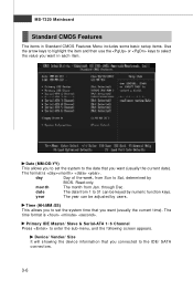
Read-only. month The month from Sun to Sat, determined by BIOS. year The year can be adjusted by numeric function keys. The time format is . Primary IDE Master/ Slave & Serial-ATA 1~6 Channel Press to the IDE/ ...
Read-only. month The month from Sun to Sat, determined by BIOS. year The year can be adjusted by numeric function keys. The time format is . Primary IDE Master/ Slave & Serial-ATA 1~6 Channel Press to the IDE/ ...
User Guide
Page 47
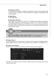
...disks. S.M.A.R.T. Available options: [None], [360K, 5.25 in.], [1.2M, 5.25 in.], [720K, 3.5 in.], [1.44M, 3.5 in.], [2.88M, 3.5 in.]. This sub-menu shows the CPU information, BIOS version and memory status of floppy drives installed. Important IDE Primary M aster/ Slave & Serial-ATA1~6 are appearing when you to the SATA connector on the...it and the devices is going to fail to set the type of your disk status to enable or disable the LBA Mode. BIOS Setup LBA/Large M ode This allows you to predict hard disk failure. is a utility that is not already formatted with LBA mode ...
...disks. S.M.A.R.T. Available options: [None], [360K, 5.25 in.], [1.2M, 5.25 in.], [720K, 3.5 in.], [1.44M, 3.5 in.], [2.88M, 3.5 in.]. This sub-menu shows the CPU information, BIOS version and memory status of floppy drives installed. Important IDE Primary M aster/ Slave & Serial-ATA1~6 are appearing when you to the SATA connector on the...it and the devices is going to fail to set the type of your disk status to enable or disable the LBA Mode. BIOS Setup LBA/Large M ode This allows you to predict hard disk failure. is a utility that is not already formatted with LBA mode ...
User Guide
Page 48
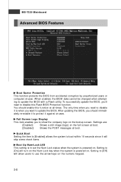
...to boot within 10 seconds since it against viruses. Quick Boot Setting the item to [Enabled] allows the system to update the BIOS. To successfully update the BIOS, you to use the arrow keys on the bootup screen. Setting to [On] will allow users to show the company logo ...the numeric keypad. 3-8 Full Screen Logo Display This item enables you 'll need to update the BIOS with a Flash utility. Settings are: [Enabled] Shows a still image (logo) on . W hen enabled, the BIOS' data cannot be changed when attempting to disable it is powered on the full screen at boot. ...
...to boot within 10 seconds since it against viruses. Quick Boot Setting the item to [Enabled] allows the system to update the BIOS. To successfully update the BIOS, you to use the arrow keys on the bootup screen. Setting to [On] will allow users to show the company logo ...the numeric keypad. 3-8 Full Screen Logo Display This item enables you 'll need to update the BIOS with a Flash utility. Settings are: [Enabled] Shows a still image (logo) on . W hen enabled, the BIOS' data cannot be changed when attempting to disable it is powered on the full screen at boot. ...
User Guide
Page 49
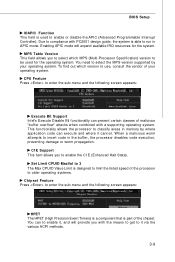
... appears: HPET The HPET (High Precision Event Timers) is a component that is able to it cannot. CPU Feature Press to compliance with a supporting operating system. BIOS Setup IOAPIC Function This field is used for the system. Enabling APIC mode will provide you with the means to get to run in the...
... appears: HPET The HPET (High Precision Event Timers) is a component that is able to it cannot. CPU Feature Press to compliance with a supporting operating system. BIOS Setup IOAPIC Function This field is used for the system. Enabling APIC mode will provide you with the means to get to run in the...
User Guide
Page 50
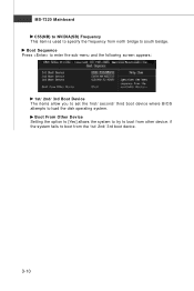
MS-7320 Mainboard C55(NB) to NVIDIA(SB) Frequency This item is used to specify the frequency from the 1st/ 2nd/ 3rd boot device. 3-10 if the system fails to boot from north bridge to south beidge. Boot From Other Device Setting the option to [Yes] allows the system to try to load the disk operating system. Boot Sequence Press to enter the sub-menu and the following screen appears: 1st/ 2nd/ 3rd Boot Device The items allow you to set the first/ second/ third boot device where BIOS attempts to boot from other device.
MS-7320 Mainboard C55(NB) to NVIDIA(SB) Frequency This item is used to specify the frequency from the 1st/ 2nd/ 3rd boot device. 3-10 if the system fails to boot from north bridge to south beidge. Boot From Other Device Setting the option to [Yes] allows the system to try to load the disk operating system. Boot Sequence Press to enter the sub-menu and the following screen appears: 1st/ 2nd/ 3rd Boot Device The items allow you to set the first/ second/ third boot device where BIOS attempts to boot from other device.
User Guide
Page 51
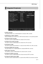
... invoke the Boot ROM of the LAN controller. Onboard IEEE1394 Controller This item allows you to enable/disable the onboard external SATA controller. Integrated Peripherals BIOS Setup USB Controller This setting allows you to enable/disable the onboard audio controller. HD Audio Controller This setting is used to enable/disable the...
... invoke the Boot ROM of the LAN controller. Onboard IEEE1394 Controller This item allows you to enable/disable the onboard external SATA controller. Integrated Peripherals BIOS Setup USB Controller This setting allows you to enable/disable the onboard audio controller. HD Audio Controller This setting is used to enable/disable the...
User Guide
Page 52
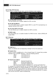
... appears: On-Chip IDE Controller This item allows you to enable/ disable the RAID function. PCI IDE BusMaster This item allows you to enable/ disable BIOS to used PCI busmastering for reading/ writing to enter the sub-menu and the following options: [3BC] Line Printer port 0 [278] Line Printer port 2 [378...
... appears: On-Chip IDE Controller This item allows you to enable/ disable the RAID function. PCI IDE BusMaster This item allows you to enable/ disable BIOS to used PCI busmastering for reading/ writing to enter the sub-menu and the following options: [3BC] Line Printer port 0 [278] Line Printer port 2 [378...
User Guide
Page 53
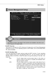
If your BIOS supports S3 sleep mode. tains all system context. [S3] The S3 sleep mode is a lower power state where the in formation of system configuration and ... power state. Set- The information stored in memory will be used to activate the ACPI (Advanced Configuration and Power Management Interface) Function. Power Management Setup BIOS Setup Important S3-related functions described in this field. tings are available only when your operating system is saved to main memory that remains powered...
If your BIOS supports S3 sleep mode. tains all system context. [S3] The S3 sleep mode is a lower power state where the in formation of system configuration and ... power state. Set- The information stored in memory will be used to activate the ACPI (Advanced Configuration and Power Management Interface) Function. Power Management Setup BIOS Setup Important S3-related functions described in this field. tings are available only when your operating system is saved to main memory that remains powered...

User Guide
Page 55
Resume by Onbaord LAN W hen set to [Enabled], the feature allows your system to enable or disable the feature of booting up the system on LAN device. BIOS Setup Resume by RTC Alarm The field is used to be awakened from the power saving modes through any event on a scheduled time/date. 3-15
Resume by Onbaord LAN W hen set to [Enabled], the feature allows your system to enable or disable the feature of booting up the system on LAN device. BIOS Setup Resume by RTC Alarm The field is used to be awakened from the power saving modes through any event on a scheduled time/date. 3-15


