MSI PM8M3-V Support Question
MSI PM8M3-V Support Question
Find answers below for this question about MSI PM8M3-V - Motherboard - Micro ATX.Need a MSI PM8M3-V manual? We have 1 online manual for this item!
Question posted by firdaussmn on April 7th, 2012
Bios Problem
I had problem when update bios on MSI PM8M3-V H board. At first everything running smooth. Suddenly the LCD monitor shut down and appear "No Input Signal"..when i restart the pc its appear again (LCD blank) but fan on board still running. What the problem with my bios?? And can i recover back like before if the bios problem??
Current Answers
Related MSI PM8M3-V Manual Pages
User Guide - Page 1
... receiver is encouraged to try to radio communications. These limits are designed to provide reasonable protection against harmful interference in order to operate the equipment.
Micro-Star International MS-7211
This device complies with the emission limits. Operation is subject to the following two conditions: (1) this device may cause harmful interference...
User Guide - Page 2
... are registered trademarks of NVIDIA Corporation in the United States and/or other countries.
NVIDIA, the NVIDIA logo, DualNet, and nForce are registered trademarks of MICRO-STAR INTERNATIONAL. Award® is a registered trademark of American Megatrends Inc. AMI® is a registered trademark of Phoenix Technologies Ltd. Copyright Notice
The material in...
User Guide - Page 7
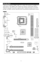
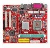
... PM8M3-V is design based on VIA® P4M800 & VIA® VT8237R Plus chipsets for the Intel® P4 processors supporting Hyper-Threading Technology in the LGA775 package, the PM8M3-V delivers a high performance and professional desktop platform solution. Layout
1 Designed for optimal system efficiency. Introduction
Thank you for choosing the PM8M3-V (MS-7211 v1.x) Micro-ATX...
User Guide - Page 8
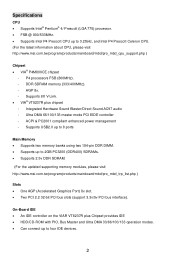
... PC3200 (DDR400) SDRAMs. • Supports 2.5v DDR SDRAM.
(For the updated supporting memory modules, please visit http://www.msi.com.tw/program/products/mainboard/mbd/pro_mbd_trp_list.php )
Slots • One AGP ...using two 184-pin DDR DIMM. • Supports up to four IDE devices.
2 On-Board IDE • An IDE controller on the VIAR VT8237R plus chipset - Integrated Hardware Sound Blaster...
User Guide - Page 9
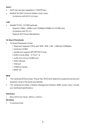
...audio codec.
-
LAN • Realtek® 8100C / 8110SB (optional).
- Dimension • Micro-ATX Form Factor: 245mm x 210mm Mounting • 6 mounting holes.
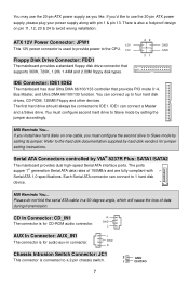
3 Compliance with 360K, 720K,... pin header - 2 SATA 150
BIOS • The mainboard BIOS provides "Plug & Play" BIOS which detects the peripheral devices and
expansion cards of the board automatically. • The mainboard provides...
User Guide - Page 10
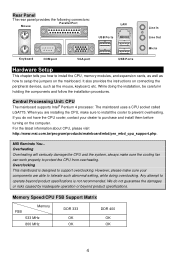
...174; Pentium 4 processor.
For the latest information about CPU, please visit http://www.msi.com.tw/program/products/mainboard/mbd/pro_mbd_cpu_support.php. However, please make sure your dealer to ...purchase and install them before turning on the computer. MSI Reminds You... Any attempt to operate beyond product specifications. It also provides the ...
User Guide - Page 12
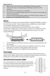
... ATX 24-pin power supply. A 300W or above power supply is 20 cycles. Check the information in PC Health Status of H/W Monitor... must be installed. (For the updated supporting memory modules, please visit http://www.msi.com.tw/program/products/mainboard/mbd/pro_mbd_trp_list...BIOS for the power system. The plastic clip at least one notch on the slots. Power Supply
The mainboard supports ATX...
User Guide - Page 13
....
If you must configure second hard drive to Slave mode by hard disk vendors for jumper setting instructions. MSI Reminds You... CD In Connector: CD_IN1
R
The connector is for CD-ROM audio connector. ATX 12V Power Connector: JPW1 12V
This 12V power connector is connected to the hard disk documentation supplied by...
User Guide - Page 14
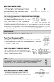
... to connect to the front audio header, pins 5 & 6, 9 & 10 have signal output directed to take note that the red
Control Sensor
+12V GND
CPU_FAN1
Sensor +12V GND
SY S _ FAN 1/ PWR _FAN
wire is the positive and should be updated.
2
2
1
1
BIOS Flash Unlocked BIOS Flash Locked
Fan Power Connectors: CPUFAN1/SYSFAN1/PWRFAN1
The 4-pin CPUFAN1...
User Guide - Page 15
...9
RI
Indicate
PIN SIGNAL DESCRIPTION
2
SIN
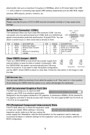
Serial in the image to keep the data of 3D graphics. MSI Reminds You... Avoid clearing...mainboard offers one 9-pin male DIN connector COM 1 (on board that the pins of VCC & GND must be connected correctly... high-speed USB interface peripherals such as jumpers, switches or BIOS configuration.
9 AGP is an interface specification designed for 8x/...
User Guide - Page 16
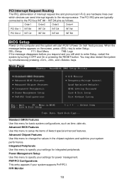
... entry appears if your system performance. H/W Monitor
10 Integrated Peripherals Use this menu to specify your settings for integrated peripherals.
When the
message below appears on ...INT A#
PCI Slot 2 INT C#
INT D#
INT A#
INT B#
BIOS Setup
Power on the screen, press key to enter Setup, restart the
system by simultaneously pressing , , and keys. PCI Interrupt Request Routing...
User Guide - Page 17
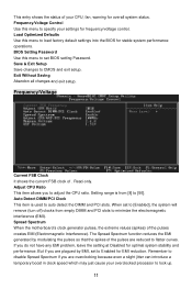
...problem, leave the setting at Disabled for optimal system stability and performance. Auto Detect DIMM/PCI Clock This item is from empty DIMM and PCI slots to minimize the electromagnetic interference (EMI). Spread Spectrum When the motherboard... EMI (Electromagnetic Interference). Read-only. BIOS Setting Password Use this menu to set BIOS setting Password.
Setting range is used ...
User Guide - Page 64
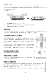
... +5V GND +3.3V +3.3V
1 13
GND +5V +5V +5V Res GND GND GND PS-ON# GND -12V +3.3V
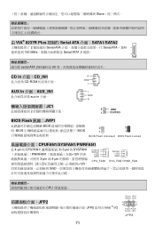
ATX 12V JPW1
12V
此 12V CPU 供电。
12V
FDD1
1 FDD1,支持 360K, 720K, 1.2M,...IDE1 接口。IDE1 1 个 Master 1 个 Slave
58 http://www.msi.com.tw/program/products/mainboard/mbd/pro_mbd_trp_list.php DDR 内存
Volt
Notch
1.
User Guide - Page 65
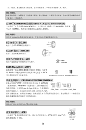
...;CD_IN1
R
CD-ROM
GND
L
AUX In 接口:AUX_IN1
aux-in 接口。
JC1
2
L GND R
2
GND
1
CINTRO
BIOS Flash 跳线:JWP1
BIOS BIOS BIOS
2
2
1
1
BIOS Flash Unlocked BIOS Flash Locked
CPUFAN1/SYSFAN1/PWRFAN1
此 4-pin 的 CPUFAN1 3-pin 的 SYSFAN1 PWRFAN1 12V 3-pin 或 4-pin 12V,
Control...
User Guide - Page 76
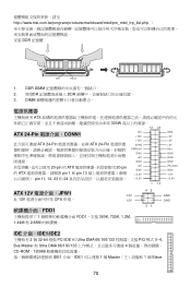
...+5V GND +3.3V +3.3V
GND +5V +5V +5V Res GND GND GND PS-ON# GND -12V +3.3V
1 13
ATX 12V JPW1 12V
此 12V CPU 供電。
12V
FDD1
1 FDD1,支援 360K, 720K, 1.2M...20171;面。IDE1 1 個 Master 1 個 Slave
70 http://www.msi.com.tw/program/products/mainboard/mbd/pro_mbd_trp_list.php DDR 記憶體
Volt
Notch
1.
User Guide - Page 77
...;CD_IN1
R
CD-ROM
GND
L
AUX In 介面:AUX_IN1
aux-in 介面。
JC1
2
L GND R
2
GND
1
CINTRO
BIOS Flash 跳線:JWP1
BIOS BIOS BIOS
2
2
1
1
BIOS Flash Unlocked BIOS Flash Locked
CPUFAN1/SYSFAN1/PWRFAN1
此 4-pin 的 CPUFAN1 3-pin 的 SYSFAN1 PWRFAN1 12V 3-pin 或 4-pin 12V,
Control...
User Guide - Page 88
... 1 CPU CPU 2. CPU
4. DIMM
ATX
82 CPU
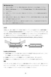
5. DDR DIMM VOLT
め、DIMM 1 2. DIMM DIMM 3. CPU 20
1GB 184 2 DDR DIMM DDR333/DDR400 SDRAM 1 つの DIMM http://www.msi.com.tw/program/products/mainboard/mbd/pro_mbd_trp_list.php )
Volt
Notch
Installing DDR Modules 1. BIOS の H/W Monitor PC Health Status にある CPU...
User Guide - Page 91
VCC(1) VCC(2)
GND USB1USB1+
MSI Reminds You...
VCC ピンと GND
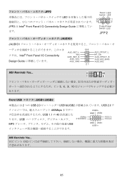
85 JFP2
Reset HDD
Switch LED...® Front Panel I/O Connectivity Design Guide
AUD_RET_L Key
AUD_RET_R AUD_VCC
AUD_GND
10 9 21
AUD_FPOUT_L HP_ON
AUD_FPOUT_R AUD_MIC_BIAS AUD_MIC
MSI Reminds You...
5、6、9、10
Front USB JUSB1/JUSB2
2 つの USB 2.0 USB1&USB2 USB 2.0...
User Guide - Page 92

...PIN SIGNAL DESCRIPTION
PIN SIGNAL ...DESCRIPTION
1
DCD
Data Carry Detect
2
SIN
Serial in or receive data
3
SOUT Receive Data Transmit
4
DTR
Serial out or transmit data
5
GND
Data
6
DSR
Data Set Ready
7
RTS
Request To Send Ring
8
CTS
Clear To Send
9
RI
Indicate
10
X
X
クリア CMOS JBAT2
CMOS RAM JBAT2 の 1-2 CMOS CMOS 2-3
MSI...
User Guide - Page 95
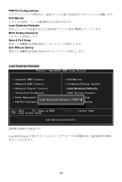
PNP/PCI Configurations PCI H/W Monitor Load Optimized Defaults BIOS BIOS Setting Password Save & Exit Setup CMOS Exit Without Saving CMOS
Load Optimized Defaults
Load BIOS Default
89
Similar Questions

Which Way I Need To Put Cmos Battery
Which way i need to put cmos battery
Which way i need to put cmos battery
(Posted by Anonymous-172123 1 year ago)

How To Download
How to download MSI P55M-GD45 - LGA 1156 Intel P55 Micro ATX Motherboard ManualThanks
How to download MSI P55M-GD45 - LGA 1156 Intel P55 Micro ATX Motherboard ManualThanks
(Posted by droidxacer 7 years ago)
P4m800ce-8237 Drivers
motherboard drivers for p4m800ce-8237 socket775
motherboard drivers for p4m800ce-8237 socket775
(Posted by bongnat73 10 years ago)

I Have The Same Problem, Only Difference Is In The Motherboard. I Have
K9N6SGM-V motherboard.
K9N6SGM-V motherboard.
(Posted by barkoczyrichard 11 years ago)

Shuts Down After A Few Minutes Of Warming Up
What do you think is causing my motherboard to shut down and the power button blinks. This occurs se...
What do you think is causing my motherboard to shut down and the power button blinks. This occurs se...
(Posted by geewhiz 11 years ago)